Electrical

Landing light wiring; lower shelf detail

I swear, I’ve been trying to work this week, but now that we’re a week+ out from all the heavy rain, the mosquito population boom is in full swing, which makes being out in the hangar any time in the afternoon an unpleasant thing. Saturday meant I could finally get out there in the morning when things were a little quieter.
 
I will say though, it hasn’t been a dull week. I took the time to start pulling the trigger on a lot of big purchases, specifically stuff whose lead time I was worried about. I now have my order in for a Whirl Wind 300-72 prop, and I just need to send in my order forms to Titan for my engine and Van’s for my finish kit. I also hit up the three popular interior vendors, and will probably be mailing off that order form early next week as well. Finally, I’m waiting on some information from Titan so I can send my order to SDS fo the CPI2 ignition system – which I want on hand so I can finalize the avionics shelf stuff behind the panel. Oh, and I also ordered and received my ELT this week, and hopefully should get my voltage regulators from B&C in the semi-near future.

This should take care of all the long lead-time stuff, the things that have the potential to stop me from making steady progress into next year. I think the only thing I still need to find out about is my exhaust from Vetterman. I saw some comments on VAF this past week that imply they may be pretty busy right now too. I note that Aircraft Spruce sells some Vetterman products, but I don’t think they have the specific exhaust I want – as far as I can tell, they stock the two-pipe crossover systems, but I want the four-pipe, which should make the cowling a little less busy. Guess I’d better reach out about that next week too…

 
Anyway…let’s talk about this weekend. The Spruce order I received this week included the small snap bushings that I needed to work out the wiring issues with the landing lights. I mentioned this a while back, but to review, the Flyleds light units have two sets of terminals: the taxi-light terminals are on the back side of the light unit, but the landing-light terminals are on the front. I was stuck a while back on figuring out how to route both those pairs of wires to a single plug, while still allowing the light unit to be removed from the mount. Basically, I needed a set of wires to pass through the light unit.
 
What I worked out was to add a tiny hole in the edge of the light unit, outside the actual printed board area, with a snap bushing, and then to modify the mount to accommodate this. Getting this done started with a whole lot of careful measuring, thinking, marking, reconsidering, and so forth. I didn’t have a lot of margin outside the circuit board area to get this done, so getting this right was pretty important.
 
But eventually I was satisfied and drilled my nice little 1/4” hole, which can be seen below. Note the circular line just inside the hole and outside the terminal; this is the edge of the “safe zone,” ie the area I really needed to make sure I didn’t breach: 

Next up, I needed to adapt the mount to accommodate this hole and the snap bushing. I started by screwing each light in place, and using the hole to trace a starting point for the mount modification:

That was followed by a fair amount of trial-and-error, trying to remove just enough material to clear the snap bushing. It took a bit, but eventually it all worked out:

Next up, I went to work adding the wiring pigtails, which will stretch to the outboard rib and mate up with a connector from the main wiring. Here we can see the power and ground wires for the landing lights, going into the snap bushing:

Then, from the back, we have the wires from the taxi light. These wires pass through a sort of tight space between the two pieces here, which got me worried about chafing, so I added some snakeskin wrap and secured it with heat shrink. The unwrapped wires are the ones from the landing light:

Each stub harness was then finished with a four-pin molex connector. This was really my first chance to use my printable heat shrink, which I’ll be making extensive use throughout the aircraft. I also got to work on my cable lacing chops a bit – the job I did on the pitot heat harness a while back was kind of so-so, but I found a nice technique video on Youtube that helped me do these a lot more efficiently and cleanly:

 And then it was time to put these back in their box…again. I moved on to one detail I glossed over for the lower shelf (where the fuse blocks will live) – I needed to secure the two hinge pins. Nothing really fancy here; I cut two hinge eyelets, added a strip of sheet to tie them together, then located and added a nutplate in the bulkhead for the retainer to tie into. Now my shelf hinge pins are properly secured:

It was about this time that the invading mosquito force started ramping up, so I made that quitting time. I’m kind of thinking I might go ahead and mount the fuse blocks and other stuff to this shelf, maybe even start tying together the components that don’t require external wiring. Except I think I need some of the heavier-gauge wire to do that. Guess I might be making another order for stuff this week. I’m starting to think that shipping charges might make up 5% or so of the total build cost…

Posted in Electrical | Hours Logged: 4.5

Ignition switch harnesses

Started the day off today with some much-needed cleaning, though it had an ulterior motive as well – to clear up some good working space on my big table. I wasn’t sure whether I wanted to start mounting things the fuse block shelf, or something else, but eventually I settled on at least starting with some more harness work…which ended up being basically the one thing I worked on today.

For the backstory – these switches will be for the CPI2 electronic ignition. Since this will be my sole form of ignition, I’m ordering a dual-ECU system for redundancy. Accordingly, I need a separate power switch for each ECU. To make things more fun, each switch needs to be double-pole – the CPI2 had separate power feeds for the ECU itself and for each ECU’s associated coil pack.

That’s not the end of the fun, though. As outlined above, each switch will control the power feeds to one of the ECUs. But since the CPI2 has its own dedicated backup battery, all that will happen if the power is turned off while the engine is running is that the CPI2 will automatically switch to backup power. This is actually a good thing for preflight purposes – by turning the power off, I can test that the backup battery switchover works as expected. That’s pretty important, since losing power to the ignition means the engine goes quiet.

Anyway, the other takeaway here relates to the traditional preflight mag check, during which each magneto is switched off in succession to check that the engine will run on just one. I want similar functionality here, but as outlined above, turning the power off won’t cut it. The CPI2 does provide a function from the controller to do this, but it’d be nicer to have external switches. These could also come in handy if I ever need to cut the engine right now, ie when pulling the mixture is too slow. The CPI2 provides kill inputs for this purpose.

The question becomes how to do this. This convenience didn’t seem worth adding two more kill switches, but integrating it into the existing two switches would work well. The end result is that I bought three-pole, double-throw switches – up is power on, center is power off, and down (a momentary position) sends the kill signal for one coil pack. So the runup procedure will be to kill power to verify backup battery functionality, then pushing each switch down in succession to test individual coil packs.

Here’s the catch with this plan – while single/double pole/throw switched can be found just about anywhere, these beasts aren’t so common. That’s a concern if one of these ever craps out, since it’s a safety-of-flight item. Being stuck somewhere while waiting on a Digit-Key order doesn’t sound like much fun. So when I ordered these a while back, I went ahead and ordered three so I could carry a spare.

One final bit of fun – this particular configuration was only available with solder lugs. I would have preferred fast-on tabs (which all the other switches have), but, well, too bad. So to facilitate a possible in-the-field swap, I decided to install a stub harness on each switch to allow for easy swapping.

That’s a really long way of providing background for what I did today, which was to cut the various wire colors and gauges, solder them to the appropriate switch lugs, heat shrink over those joints, print heat shrink labels for the wires, crimp on Molex pins, and insert the pins into their connectors. Well, only 2/3 of the way for that last one…because I forgot I ordered a spare switch on that Digit-Key order, and only ordered two six-pin connector sets. Oh well, when I get the connector all I’ll have to do is insert the pins.

So yeah, this is what I got out of those three hours of work:

Posted in Electrical | Hours Logged: 3

Switch console fab

So a couple weekends ago I made my first failed attempt at getting the mount holes done in the switch console. That, of course, ended in me ordering a replacement part. Well, the replacement (plus some raw stock for making a better switch retainer plate) came in last weekend. This week I’ve again been sort of dodging the mosquito population, though it’s finally died off enough that I did some evening work tonight, and I decided to pick back up on the new console.

Now, the issues last time mostly revolved around the holes in the console not lining up with the holes in the retainer plate. At the time I’d decided that when I redid this, I’d rivet the plate to the console to make sure everything lined up. In the intervening time, though, I decided that that wasn’t necessary, and would add decent complexity getting those rivet holes lined up. The real issue wasn’t so much a wandering step drill as it was my dumb decision to make those holes while holding work pieces by hand on the drill press.

So I decided to have a go at it doing it the same way as last time – drilling the pilot holes in assembly between the two pieces, but enlarging the holes to final size separately. This time, though, I’d make sure the work pieces were clamped securely while drilling. To facilitate this, I built up a sort of jig with a couple 2x4s. This made a piece tall enough for the console to sit on, and I next used the console to drill holes in the block matching the screw holes, which would allow the console to be clecoed in place while working.

Then I made up another retainer plate strip, laid out the pilot holes on the console, drilled those pilot holes, and transferred those holes to the retainer plate. Here’s the console with pilot holes clecoed to the block:

Next up was laying out and drilling the small retainer holes in the backing plate. Since I wanted to use that same jig block for drilling the retainer as well, I drilled the retainer plate with it clecoed to the block using the pilot holes. This allowed me to cleco both pieces to the block while drilling.

Then it was over to the drill press to start opening up the mount holes. This worked a lot better than last time, and reclamping the work for each hole was nowhere near the annoyance I might have thought it was. Here I am partway through opening up holes on the retainer plate:

Finally, after making a whole lot of metal shavings and sawdust, it was all done and it was time to see if they matched up. If they didn’t, it wouldn’t be the end of the world actually – since I didn’t mess up any of the console holes (unlike last time), worst case I could make another retainer and trace the holes from the console onto it, It’d be really painstaking to open those holes up by hand, but it’d work.

But it wasn’t necessary – everything lined up perfectly this time, and I was able to get all the switched, circuit breakers, and the PWM dimmer installed:

And of course, with that done, I just had to cleco the console into the plane. You know, just to check fitment. Very important. Plus I could lean over the cockpit and flip switches like I was doing my preflight check. Also very important.

So that was a good night’s work, and it’ll set me up nicely to start putting together the wiring harness for the console tomorrow.

In other news, manic ordering of parts has continued. I got my finish kit ordered this week, mailed off order forms for the engine and my seats, and in really big news, found out from Whirl Wind yesterday that my prop is going to ship next Tuesday! That’s barely a week-and-half turnaround on something I expected to possibly take months (based on other stories I’ve heard about Whirl Wind). To say that I’m please would be an understatement, though this also means I’ve got to find somewhere to store that thing for several months.

Next up on the ordering front is the CPI2 ignition; I shot an email off to Ross at SDS today, but didn’t hear back; I’ll probably give him a call on Monday to get that rolling. Oh, and I also got both my voltage regulators from B&C this week – another component I’ve got on hand to work out the behind-the-panel stuff.

Now I’ve just got to work on getting all these parts to fly in close formation…

Posted in Electrical, Fuselage | Hours Logged: 3

Switch console wiring, rear shelf work

Well, it was another day of road blocks of a sort, but I did my best to get stuff done in spite of it all. I’d intended to try and get most of the switch console wiring done, though I knew going on that I had at least one roadblock. One thing I replaced in this second console attempt were the circuit breakers; when I was ordering my regulators rom B&C I saw they had mini Klixon breakers, much more compact than the ones I got from Digit-Key previously. Since I was worried about the clearance between the breakers and the side of the console, going with those was a no-brainer. The problem is, these breakers need a #6 ring terminal, unlike the #8 for the original breakers. Guess what ring terminals I don’t have on hand? Yup.

But I figured I’d at least get started on the wiring stuff anyway; I’d probably not get to the point of loading up the connectors or bundling the harness, but I could at least get some terminations done. So I drug all the assorted wires needed out on the workbench, and here I was confronted with another problem: I’ve been intending to terminate the console harness with a pair of Molex Mini Fit plugs; this was the best way to get a fairly compact connector overall, since Molex doesn’t do more than two-row connectors in this form factor.

The problem is, I saw that the current rating of those connectors was fine for everything I have, but didn’t consider the wire gauge the pins could accept. And it turns out the biggest they’ll take is 18AWG, whereas I need both 14 and 12 for the seat heater and pitot heat, respectively. I did find that there’s a Mega Fit series that will work with this wire size, so I’m going to rework my connections here into a 6-pin Mega Fit connector for the high-current stuff and a 20-pin Mini for the rest. More stuff to order…

Oh, and that still wasn’t the end of it. I also didn’t have the right blade terminals for the 12AWG wire needed for the pitot heat circuit, so I couldn’t terminate those to the switch either.

I still decided to go ahead and cut the wires that I could and crimp on the terminals needed to connect them to the switches, but that was as far as I went. I’ll have to wait until I have the rest of the stuff I need before I can turn this rat’s nest into something that looks actually organized:

So – what to work on next? Part of me wanted to sit down and start getting more parts orders together, but I can do that any time, and maybe wait until tomorrow in case I find more stuff I need. I still don’t want to finalize anything on the forward shelf until I get the CPI2 ignition stuff on hand, but I’m quite confident I can get everything I need up there – and that means I can start finalizing the rear shelf.

What actually started me on this path was trying to think of other wiring things I could do fairly independently, and the one thing that came to mind was the Skyview network connections in the tailcone – specifically the runs from the network hub back to the ADAHRS units. I won’t want to bundle those until I have the trim and strobe runs going back as well, but I can still get through all the pinning. But first I needed to have the hub location nailed down.

Before that, though, I needed to actually make the shelf attachable. So I carefully positioned it, got the four screw holes drilled, and installed the nutplates in the longerons. Then I pulled out the pertinent components and worked on a decent layout for them – which I’d already roughed out, so this was just finalizing things. Nothing much changed here, except that I think I had the hub and ADS-B receivers switched previously. This new layout makes it easier to get tot he receiver’s harness connection, and positions the hub close to where the pitch servo will live. By doing that, I’ll be able to just terminate the wires on the servo with a D-sub, and plug them directly into the hub – no intermediate cable needed.

So that was pretty much today’s work – I didn’t quite get to laying out mount holes in the shelf before I had to go to an afternoon appointment. Tomorrow I should be able to get this stuff mounted and at least start on those network cable runs. And I guess place some parts orders…

Posted in Electrical, Fuselage | Hours Logged: 4

Rear shelf stuff, making a network cable

Today I picked right back up with the rear shelf. I was happy with the locations of all the components there, so I marked off and drilled all the various mount holes. The one interesting bit out of all this was the ELT, whose manual insists that I should have drilled #19 mount holes, despite all the preexisting holes in the tray being obviously sized for a 3/16 bolt or screw. So I drilled them #12 instead. This annoyed me for a bit, because I thought I’d need to order yet more fasteners for this, but wait, I did order some 10-32 screws already. Good thing I bought extras in an assortment of lengths.

Anyway, there was just an extended grind of making those holes, laying out nutplates of assorted sizes for all of them, and getting those nutplates riveted. But then it was done and I got all my stuff attached.

That allowed me to move on to the original thing that prompted wrapping up the shelf: the network cables from the network hub (second from right above) to the ADAHRS. This would be my first time assembling a Skyview network cable – hooray for new things! Now, it wasn’t strictly necessary to make these – Dynon sells prefab cables, and those probably would have been a time-saver – but by making my own, I can make them exactly the length I need and also save a decent bit of money.

They are a bit labor-intensive, though. Each cable consists of four twisted wire pairs (two power/ground and two data pairs), plus a ninth single wire. Here again, you can buy pre-twisted wire if you want, but I didn’t do that either. Twisting your own isn’t really that hard – Stein from SteinAir has a pretty good video on his Youtube channel showing how to do it with a drill, and it works well.

But first, I had to figure out how long to actually make the cables. One idea I’ve seen is to rub ribbons through the fuselage and use those as a way to measure future wiring runs. In this case, rather than going looking for ribbon somewhere in the house, I decided to use my huge surplus of static tubing instead. I figured it was a little easier to have this hold the expected routing than ribbon. Looks kind of ridiculous, but it does the job:

Now, the prefab network cables have each wire a different color, to properly differentiate between the identical pairs, but I didn’t want to spring for a bunch of special color wire. Instead, I used red/black for both power/ground pairs, and green/blue for both data pairs. I used my printable heat shrink to label the pairs so I could be sure to pin the connectors properly. After labeling one end of the wires thusly, I stripped each end, crimped on the D-sub sockets, and then very carefully pinned my first connector. Some heat shrink at the strain-relief point, and into the backshell it went:


Next up was bundling up the cable. My initial intent was to go to town cable-lacing the thing, but after just a few knots, I didn’t really like the way things were laying up. I think the lacing probably works better for non-twisted wires; in this case the twisted pairs seem to just make for a lumpy bundle between ties:

Instead I decided to use the 1/4” flex wrap I bought a while back to just enclose the entire length of the cable. This provides the sort of smooth overall finish that I’m going for, at the cost of some annoyance – getting that stuff over a bundle of wires has a sort of greased-pig quality to it. Once I got the sockets crimped on the other ends of the wires, I took it over to the fuselage and got it routed.

The question at this point was whether to go ahead and pin the other end and add the backshell, or wait until later? Leaving it as-is meant having the end of the flex wrap to possibly fray. Previously I’d imagining just having the network wires live in the larger bundle it’ll be routed with, but now that I’ve wrapped the whole thing, there’s nothing to be gained there. So I decided to go ahead and finish the cable. Later, when I pull the other wires to the tail for the tail light and elevator trim, I’ll just lace them into a single bundle in place.

But before committing to heat shrinking everything together, I tested the cable, making sure that the corresponding pins on both ends were continuous. Definitely a better-safe-than-sorry moment. There were no issues, so I finished the cable and plugged it into both ends of the run. At the moment, there’s a lot of slack, but the routing at the shelf end will be more circuitous than what’s represented here:


In the end, it was definitely tedious and time -consuming, but this was also my first time doing any actual d-sub stuff, so I imagine that the next cable will go a fair bit faster. One thing I’m thinking about doing is building up a couple dummy connectors to allow for easier testing of these cables. To do this one, I had to grab two unused pins and insert one into the location being tested on each end, and probing those with the multimeter for continuity. The pins were necessary because my probes are to large to go into the sockets. With a dummy connector, I could chain the individual circuits together and basically test them all at once. I’ll have to think about that one.

Next up, I get to repeat this exercise, except the next cable will be 2” shorter than the other one. I guess that’s when we’ll get an idea how much quicker subsequent cable build-ups will be. Now it’s time to go put together yet another Digi-Key order. Maybe a Spruce order too. Oh, and possibly SteinAir…so many things…

Posted in Electrical, Fuselage | Hours Logged: 6

Another network cable

Nothing too exciting tonight; I did some tidying up and then got to work on network cable #2. As expected, this one went a good bit faster than the first, though I also caught myself getting a little too comfortable – I started pinning up the second connector on the bench. Fortunately I realized my error before seating any pins, so I didn’t have to actually do any defining.

Testing was a lot quicker this time too. I realized that my previous idea of making a sort of loopback test plug wasn’t smart – all I’d really be testing was that al the circuits were continuous, not that they were actually paired up correctly. Instead, since I was putting together another Digi-Key order early this week, I added a couple of solder-cup DB9 connectors. I can just plug those into both ends of the network cable and use the solder cups for continuity testing.

In any case, now I’ve got network cables to both of the ADAHRS units:

Posted in Electrical, Fuselage | Hours Logged: 1.5

More switch console work

Since my Digit-Key order came in this week, and with those two network cables done, today I was able to get back to work on the switch console. It was a bit of a late start though, since there was an EAA fly-in across the runway that I spent most of the day at.

I got the terminals crimped on the remaining wires, got them in place, and commenced to bundling everything together temporarily so I could figure out the Molex plug locations and get all the wires trimmed. I got the terminals crimped on all the wires, and even got the high-current ones finished and pinned into their connector, but before I could do the same for the low-current wires, the mosquitos drove me inside. Between it being dusk and me having the hangar lights on, it was turning into a bloodbath. I guess I need to go spray out there or something.

Anyway, at some point during the work session, Josie came out and I commented along the lines of “see, it’s looking less like a rat’s nest,” to which she replied with a skeptical look. I guess I can see where she’s coming from; it looks better to me, but certainly still far from organized:

Tomorrow I ought to be able to get everything into the connectors, and then with some cable lacing this ought to morph into something that actually looks organized.

Posted in Electrical, Fuselage | Hours Logged: 2.5

Console wiring, wing wiring penetrations

Back at it with the console today. With all the wires pinned, next up was positioning the heat shrink labels and getting them shrunk. That was a bit fun trying to hold the wires where I could heat one at a time without accidentally shrinking one that wasn’t ready. Also, this printable heat shrink stuff is awesome, I’m loving this as a way to label things.

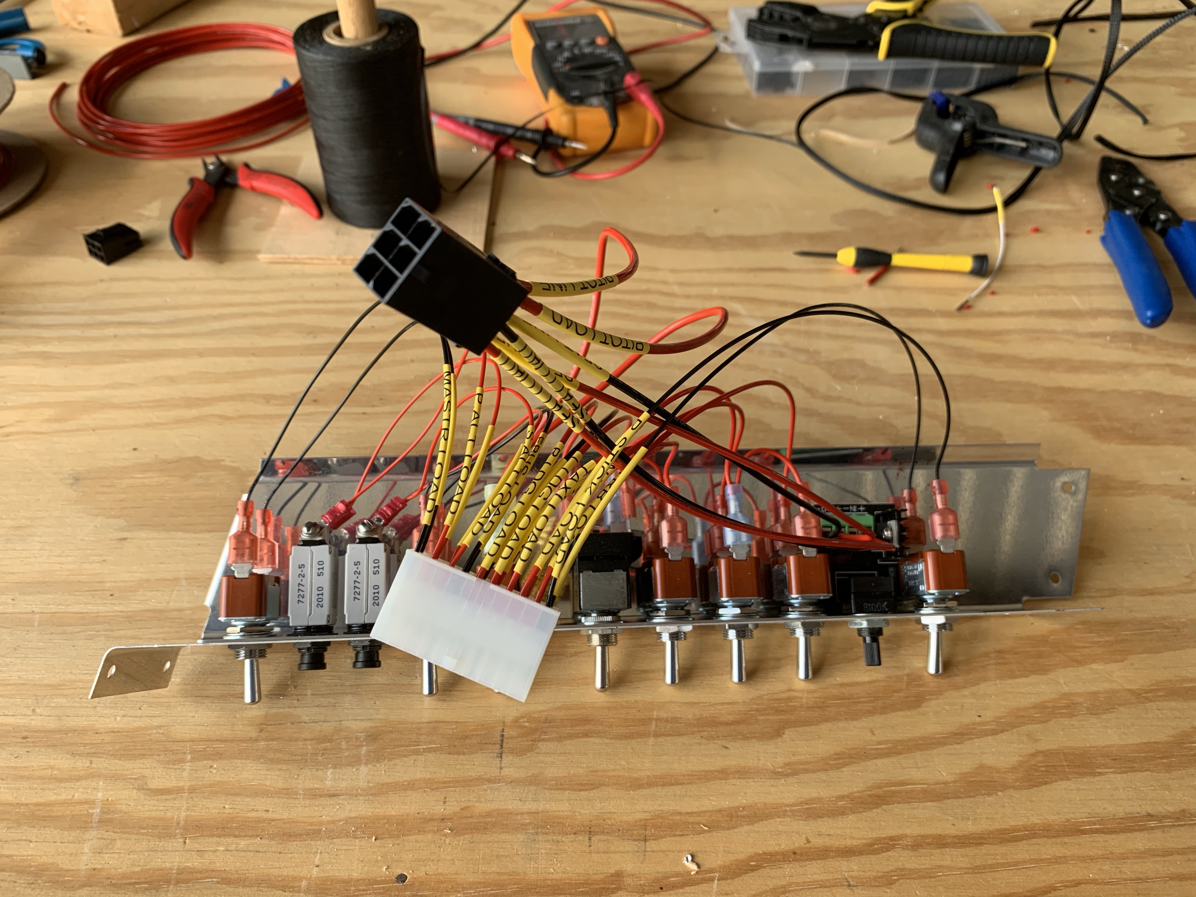
Anyway, with that done, it was time to start inserting the low-current pins into their connector housing. Continuing with a recurring theme, there wasn’t anything especially challenging here, just tedious. With both connectors in place, it’s gradually looking more organized:

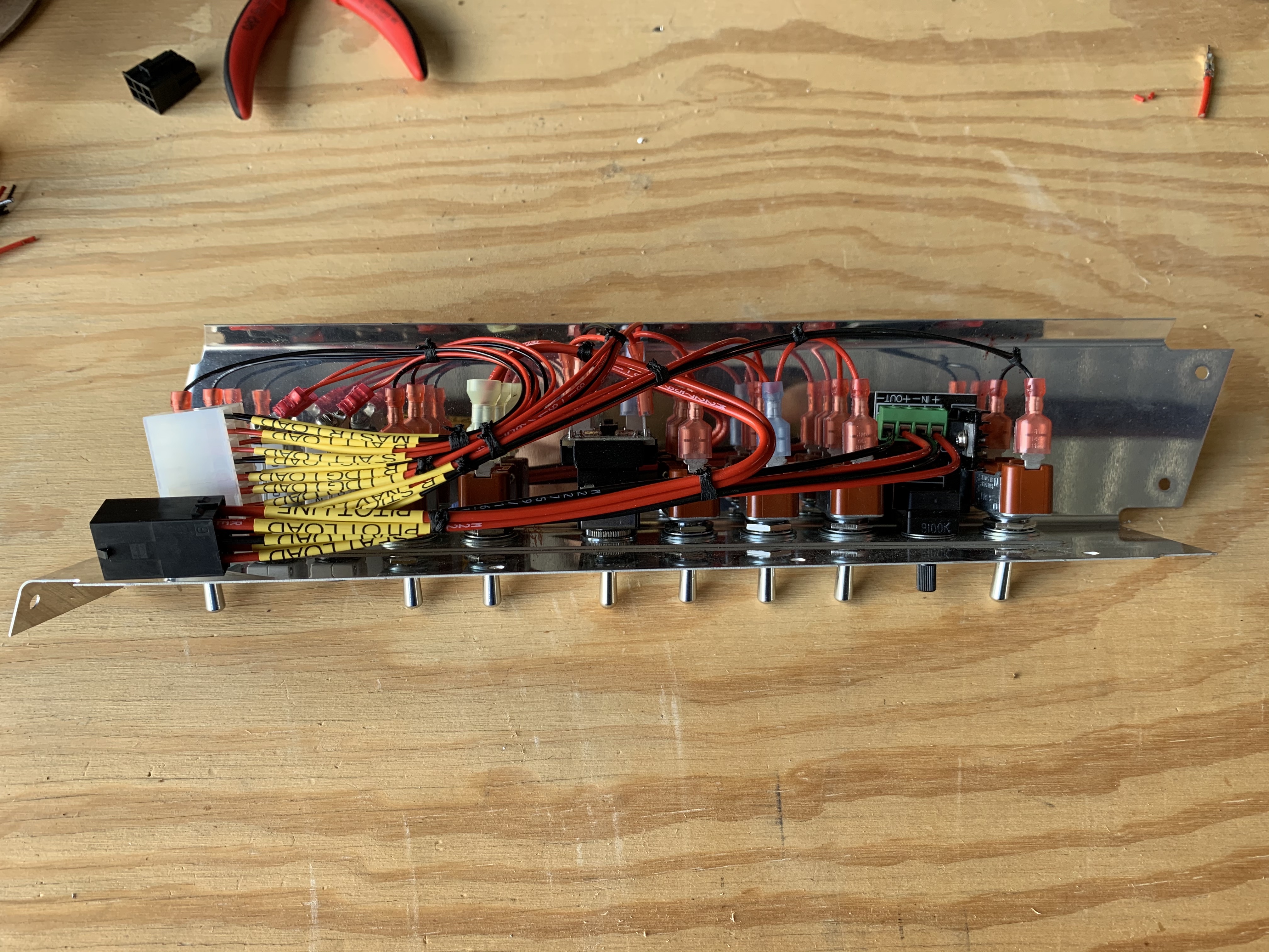
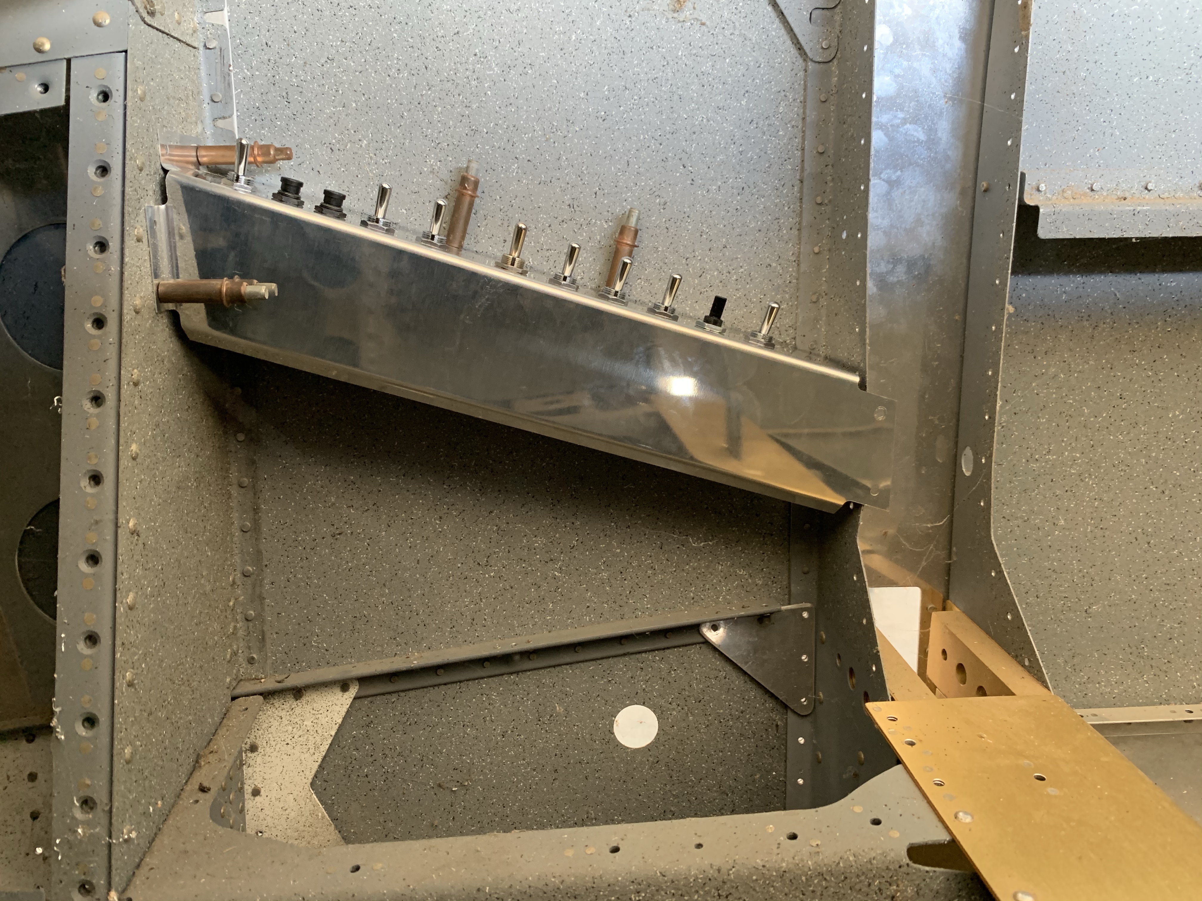
Next up, time to break out the lacing and get everything bundled. Now it unequivocally looks organized and not rat’s-nest-ey at all:

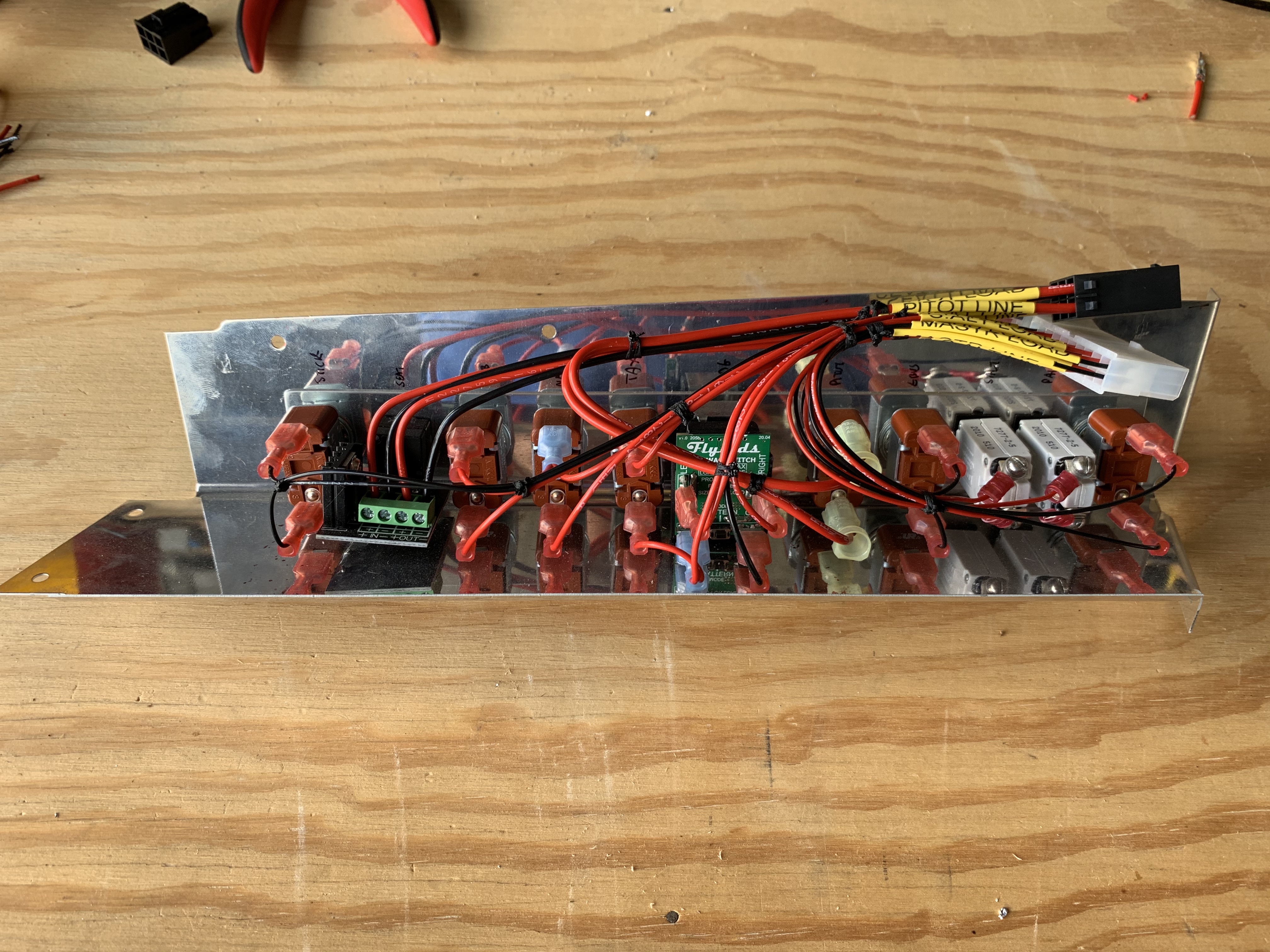
And from the opposite angle (looking from “below” rather than from the side):

Later, when this is ready to be installed for real, I intend to bundle both connector housings together with silicon tape, just for a bit more organization. Right now I’m not doing that for a couple reasons. For one, I want to be able to easily see all my heat shrink labels when it comes time to pin up the mating connectors in the fuselage harness. For another, all these switches will need to come back out of this console at some point, so I can get it painted and labeled.

Last step for this bit-o-fun was to cleco the console back in place in the fuselage. All the bundles are tucked up nicely and don’t show at all:

So…what to do next? I’ve been kind of avoiding some of the more prickly fuselage wiring prep work. I still need to do the conduit runs below the seat floor, but before I can do those I need to drill a hole in a bulkhead, but more importantly, work out the positioning of the terminal strips and other stuff just behind the spar carry through. That, in turn, is somewhat affected by exactly where the wing conduits will enter the fuselage. So I decided it was time to bite the bullet and make those holes in the fuselage.

A while back I attempted to make a jig out of scrap wood for this purpose, and after a decent amount of work, I decided I really didn’t feel like it was a great option when compared to just doing some careful measurement. The fun part of figuring out these measurements is deciding on the right reference points to use on the fuselage. What I decided to go with were the center section for fore-aft location, and the lower skin that will mate with the wing ribs for vertical location. To determine these measurements, I used a square to measure the distance from the bottom of the inboard most wing rib to the edge of the conduit, and at the same time, I marked the location on that rib flange where I took the measurement. I then measured from the aft face of the spar along the rib flange to that mark. The outside diameter of the conduit is about 7/8”, so by adding 7/16” to my vertical measurement, I had what I needed to mark the center of the hole  on the fuse.

So I started with the left side; measuring back from the center section (where it would mate with that aft face of the spar) along the lower skin, marking the fore-aft point, using my square to extend that line inboard to the side skin, then using the square to draw a vertical line from there and mark it at the appropriate distance. I did a double sanity check on the fore-aft distance, verified that it looked right, and got to drilling – first a #30 pilot hole, then going to town with a big step-drill bit. I went with 1-1/8” holes, mainly because there was a very prominent step on the bit there, but also because there’s no need to make these super precise. I may end up putting large snap bushings or grommets into these anyway.

Then it was time to do the right side. Rather than just reuse my measurements, I did the whole procedure again with the right wing, which entailed temporarily installing the conduit there (it had already been in the left wing) Upon marking the pilot hole location on the right side, I noticed that…this mark seems lower than the other one. Oh boy, time to find out which one is wrong. Sad news: these measurements were right. I made the first hole on the left side too high. Good times. Well, first thing is to go ahead with the right side hole, but be REALLY sure to get it right. Then there was the question of what to do on the right side.

There were two issues to really consider here. The first and most obvious was to consider the consequences of enlarging that hole as needed. Simply going further with the step drill would result in a seriously gaping hole, bad for both not having a super drafty cabin, and also for questions of structure. Besides, by the time I made the hole large enough, the top edge would likely be unacceptably close to the seat angles and rivet line above. No, I needed to essentially mark the correct center and redial the hole entirely. That presented a different problem: I doubted if the step drill would necessarily center itself well if it was overlapping into an existing hole.

So what I decided to do was to add a doubler; this would both help with any potential structural weakening (which I didn’t think was a huge deal, but still better safe than sorry), while at the same time allowing me to basically have virgin sheet stock when drilling the new penetration hole. OK then, time to get to work.

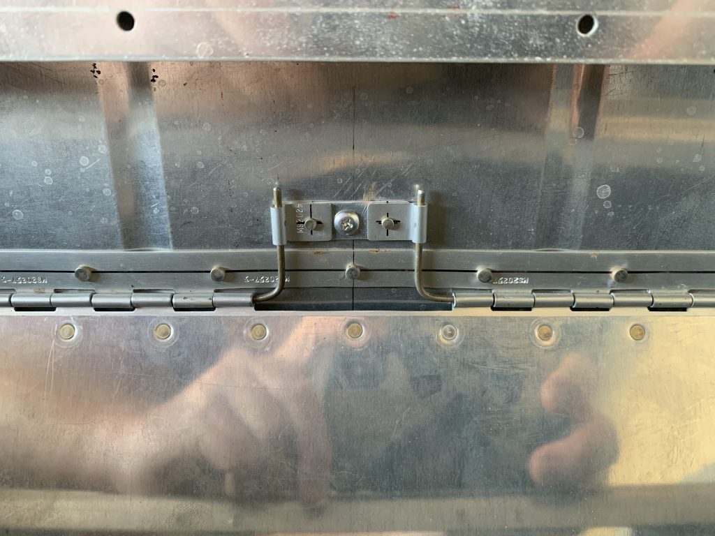
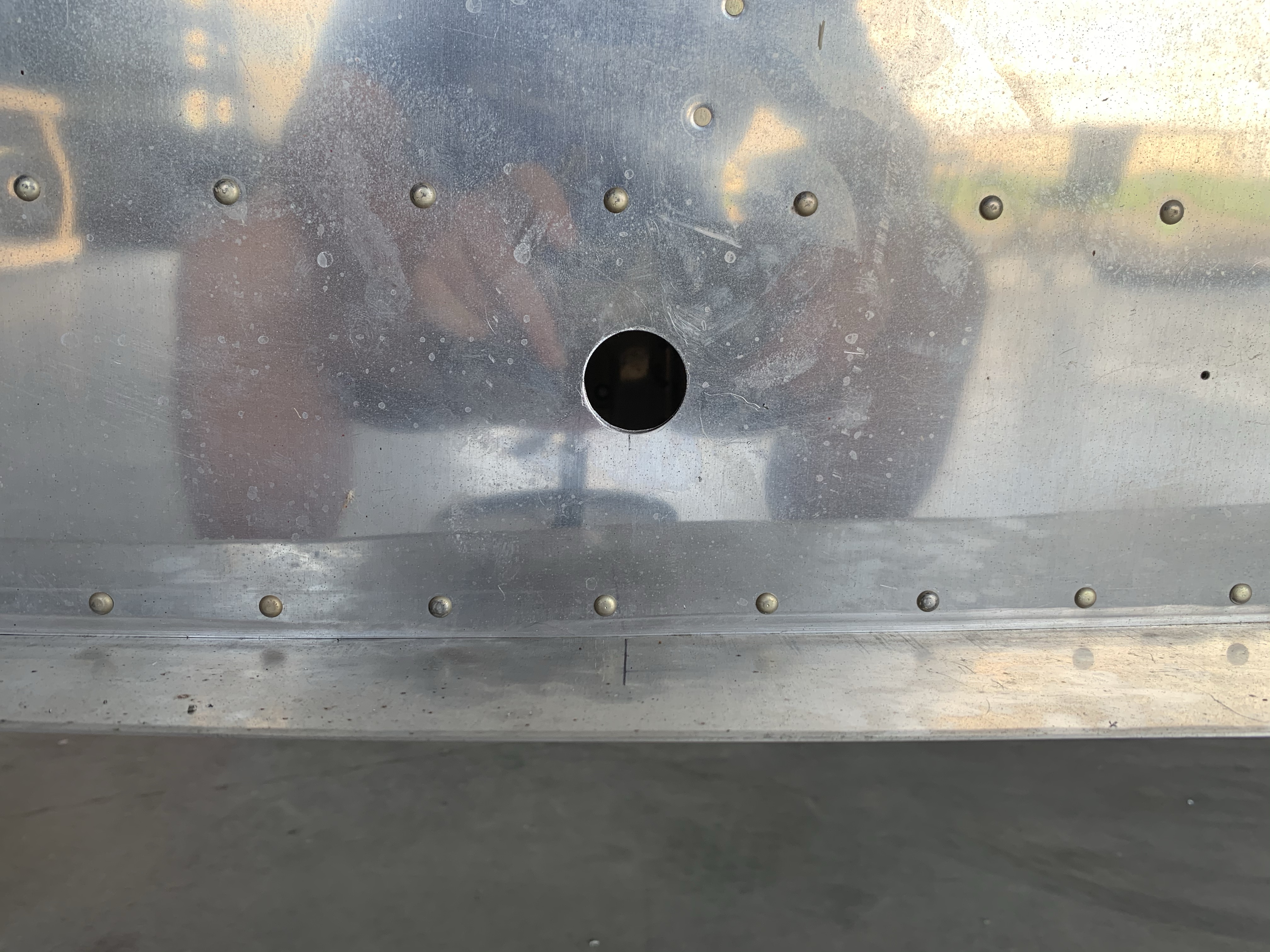
First up, here’s the offending hole. In retrospect, this is obviously wrong; the conduit sits in the bottom of the lightening holes in the ribs, and thus should be closer to the bottom of the fuse:

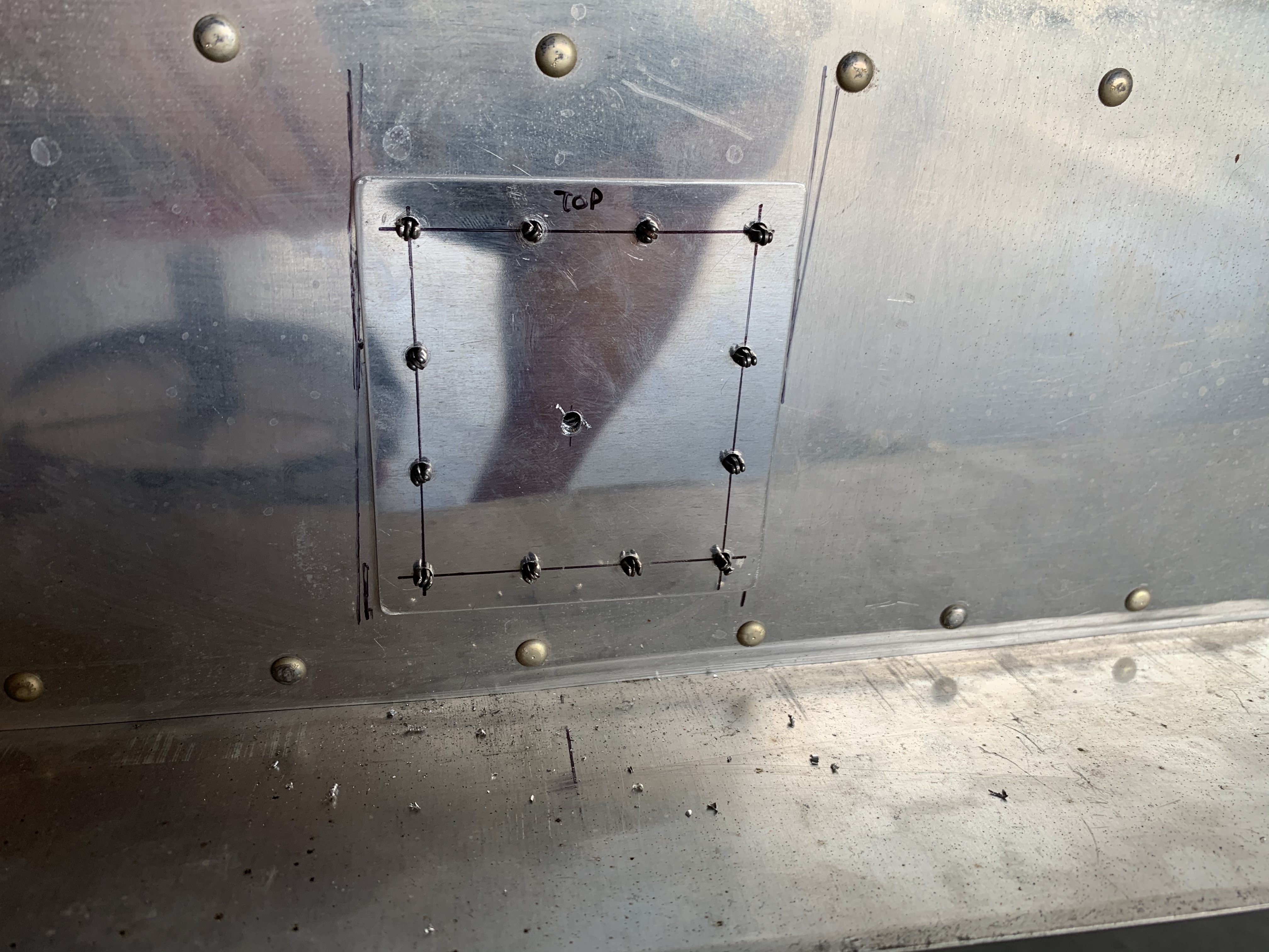
The doubler was made from .040” sheet, the same thickness as the mid side skin here. It was basically sized to provide good clearance both from the rivet rows above and below, and around the original and newly-planned hole locations. Rivet spacing is maybe a bit overboard, but it’ll definitely be strong. Here it is after drilling to the fuselage, and laying out and drilling the new center hole for the penetration:

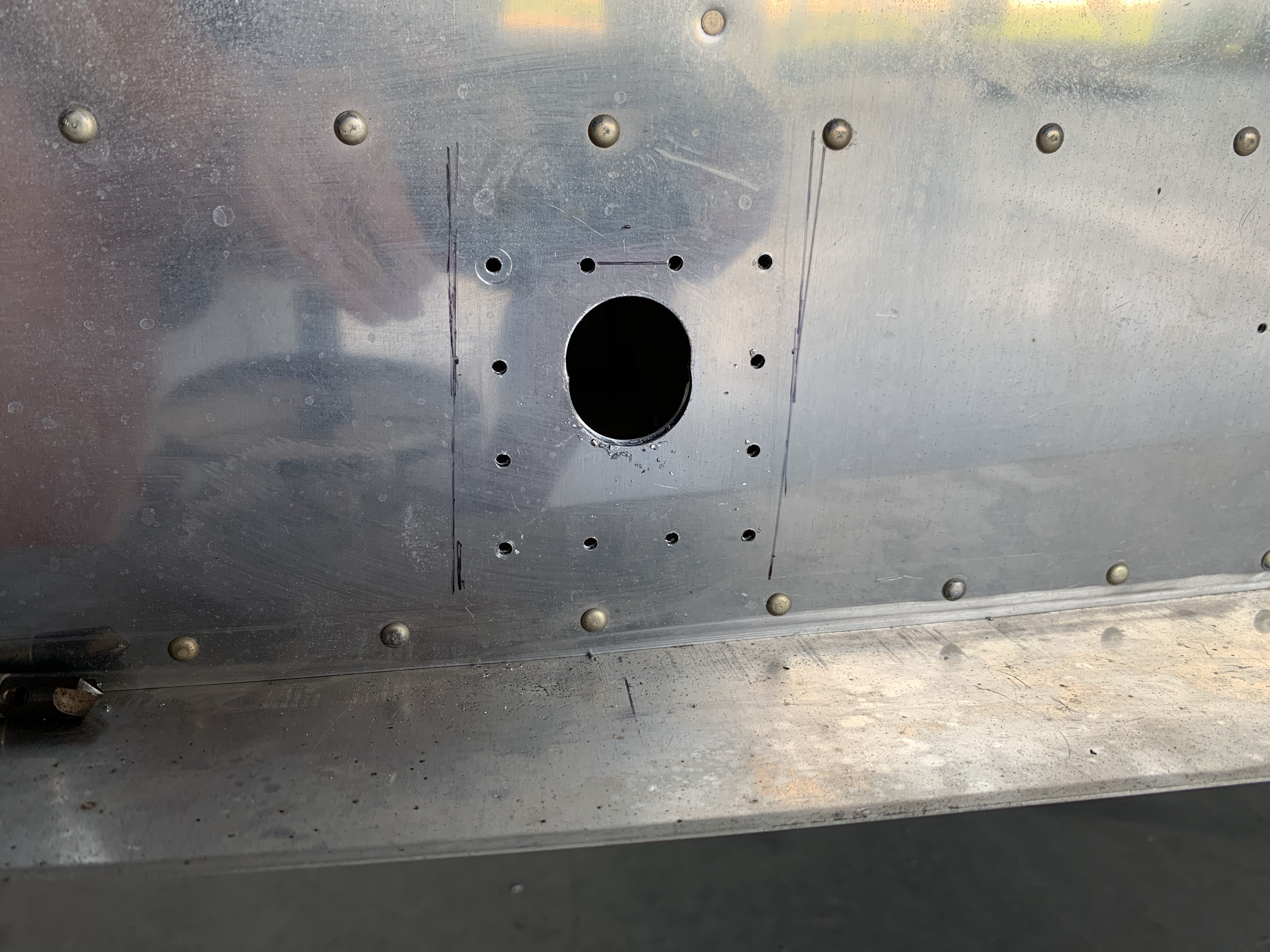
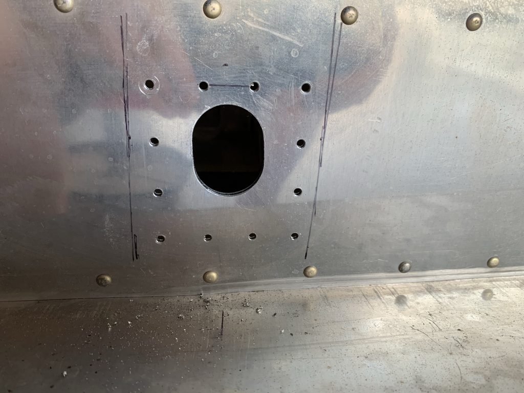
And here’s the skin after drilling the new penetration hole to final size and removing the doubler. Huh, that’s less of a sort of figure-eight hole than I expected:

A measurement check revealed that…the new hole is still too high. I screwed it up again.

I’ll be honest, some part of me considered not mentioning this misstep. It was definitely a confidence crusher, and my first gut reaction was to quit for the day in disgust. But I pretty quickly realized that as bad as fouling a thing up twice in a row sounded, the solution wasn’t that bad at all. There’s plenty of margin at the bottom of the doubler layout…I just needed to make yet another doubler, and start from scratch again marking the penetration center.

Back to not mentioning this…it would have been pretty easy to just gloss over this, but that’s just not a good way to do things, regardless of how embarrassing the mistake might have been.

Anyway, I went and made another doubler, used the first doubler to drill the rivet holes on the bench, and got it clecoed in place. Then I laid out the hole center again. This time I went back and forth between the wing and the fuselage roughly 473 times, making really really really really really sure I wasn’t going to have to write about screwing up three times in a row. Back through the drilling process again, and now I just have an even more elongated hole in the skin:

In retrospect, the doubler is almost surely structural overkill. The left side of the fuselage has a second hole far larger than this, a bit further back – this is where the fresh air intake for the rear seat will come in from a NACA duct under the wing. But as mentioned before, the doubler was useful for effectively moving the hole, and for sealing things up a bit better. I may consider adding some fabric boots where the conduit enters for good measure, but that’s a decision for another time.

I also stopped short of actually riveting the doubler in place. On the off chance that I need to enlarge the hole even more when it comes time to fit the wings, I think it’ll be easier to deal with with the doubler still removable. I should probably cleco it back in place so it doesn’t grow legs and walk away, though.

Not shown in photos here was when I started trying to lay our the terminal strips in the floor area. These will provide the interface between fuselage and wing wiring, and they’re looking to be a bit problematic actually. Since they’re long and skinny, and since I’d like them to be accessible without removing the riveted-in rear seat floors (as opposed to the removable forward seat floor), and since I’ve already got the comm antennas in that area…this might be interesting.

One possibility is mounting the strips to the side skins under the floors, assuming they won’t interfere with the rear seat footwells. Even if they don’t that location would make removing the terminals on the bottom side kind of fun. Though now that I think about it, if those are the fuselage-side terminals, then they shouldn’t need removing except in an extreme case (well, even having to remove the wings ever is already an extreme case, this would be even mores).

The other option would be to give up on my desire to have these be easily accessible – maybe they just have to go further back, under the riveted floors. Decisions, decisions…

Oh, I also have to find a home, probably down in this same area, for the Flyleds strobe controller. Looks like I’m in for a few more head-scratching and chin-rubbing work sessions.

Posted in Electrical, Fuselage | Hours Logged: 4.5

Underseat wiring prep

After a pretty lazy start to the day, I got right back to work scratching my chin while looking at how to arrange all this stuff under the seats. The good news was that it was simplified quite a bit by my decision to ditch the terminal strips. Now I just had to figure out where and how to mount the Flyleds control board. The board comes with four snap-in plastic standoffs that are kind of absurd in length:

I wasn’t quite sure I wanted to use those, so I tinkered around quite a bit here. I thought semi-seriously about working out something involving machine screws and spacers, but that would have required yet another hardware order, and so eventually practicality won the day. If I invent new methods for every little thing, not only will this project take forever to finish, but I’ll go broke from paying shipping charges.

Also, one nice thing about the plastic standoffs is that the hole locations in the mounting surface don’t have to be super precise – and in fact, I intentionally made them not quite match up with the holes in the board. Since these standoffs are so long, they allow the board to move around a little more than I like. I did an experiment with some scrap, where I set the mount holes slightly further apart than the board, with the result being that the standoffs are splayed a bit and provide just bit of extra stiffness.

This also gave me something to use as a drill template for the seat rib in the airplane. I ended up locating the board on the right-side rib, facing outboard. The long standoffs mean that the location of the footwell is a bit of a concern, but by putting the board as far aft as possible, there’s no interference (I checked by putting the forward floor assembly in place with the board in there)

The vertical orientation minimizes the space taken up on the floor/bottom skin here:

Next up, I decided it was time to address the conduit runs back to the tail section. The first order of business was to take care of the missing 3/4” hole in the bulkhead below the rear seat. I’ve probably written about this before, but for some reason there are a pair of 3/4” holes in the rear spar carry-through, but only one corresponding hole in the bulkhead aft of the spar. And getting to this location to drill a hole is challenging.

I ended up buying a hex-shank step drill bit off Amazon; this was still too large to go in the adapter for my angle drill, but that problem was easily solved by way of some home machining…by which I mean chucking the bit backwards in a drill and turning the shank against the bench grinder:

But hey, now it works in the angle drill:

After getting that hole deburred as best I could given the tight quarters, I measured and cut my two conduit lengths, and then set about the joyous task of pulling the stuff through the bulkhead holes. This isn’t too bad of a thing when you have good access, like I did for the wings a while back, but here it was a lot more awkward. Since the conduit runs close by the seat ribs, getting a solid grip on it to give the firm pull needed to get it moving was tough. Nothing to be done but just keep plugging away, though.

With that worst part done, I got to work securing the conduit ends in place. Since there aren’t any bulkheads at either end of the conduit, I needed a different way to secure the stuff. A while back I ordered some little stick-on bases that a zip tie can pass through, and this was my first time actually using them. They came with some 3M foam adhesive, but I elected to scrape it off and use some 3m VHB stuff instead, which ought to provide plenty of long-lasting adhesion.

A close look at one secured conduit end:

I also went ahead and ran pull strings through each conduit before fully securing them into place. When it was all said and done, I had a nice conduit run on each side of the aircraft:

A close look at the forward ends; on the left side, the conduit ends just ahead of the roll trim servo mount, and on the right it’s pretty similar but positioned a little further outboard:

And at the aft end, the conduits somewhat follow the baggage ribs, and end just ahead of the rear avionics shelf:

With the conduit in place, it became somewhat easier to begin visualizing the harness layout, and so I started sketching out a diagram of the harness on the large whiteboard I had nearby:

None of this is to scale at all; the intent is rather to identify “nodes” in the harness, where branching occurs. I’ll be able to use ribbons or something like that to later figure out the length of each run between nodes, which can be used to figure out the actual length of individual wire runs. It also currently glosses over what’s surely the most complex part of the whole thing, as indicated by the “panel fun” bit. I’ll need to finally settle on component positioning behind the panel before I can get that part sketched out.

I’ve seen where some people attempt to construct the entire harness outside the airplane, get it laced up all nice, and then install it. That sounds interesting, but I’m not sure it’s going to be feasible. What I’m roughly expecting right now is to get the main “trunk” of the harness – the section between the panel and the rear shelf – assembled and laced, but I expect to terminate and lace up everything else inside the plane. Fortunately most of that work will be not hard to get to (the panel area), but I’m sure it will yield some nice rats-nest photos down the line.

For now, though…I really need to pause this wiring work and get the bottom fuselage riveting done. The more stuff I put in here the less fun it’ll be to shoot those rivets, and I’ve been putting them off way too long.

Posted in Electrical, Fuselage | Hours Logged: 4.5

Service letter done, more planning

Another fairly unexciting day, following an unproductive weekend. I shot the rivets for the tailbone stiffeners for the service letter fix, then decided to look at doing some actual mounting of stuff to the fuse block shelf. So I pulled that shelf out, took it to the bench, and started laying things out again, but this time with the actual wire on hand to at least consider routing for the big power feed.

Before long, I’d decided that I no longer liked my original plan of using cheap plastic clips to secure the wire bundles here, and that I wanted to use legitimate adel clamps instead. Only problem with this is that I don’t have the right size ones on hand. Also, it’d be nice to at least get the interconnects between the fuse blocks and other stuff done, but I don’t have the right terminals on hand for that.

So long story short, looks like it’s time for yet another Spruce order.

But hey, I still did stuff, and tomorrow I should get in my new panel blank, and I can get going on attempt #2 at getting that cut.

Posted in Electrical, Fuselage | Hours Logged: 1