Fiberglass

Starting on empennage tips

Well, I’m finally forcing myself to stop procrastinating on doing fiberglass stuff. The main hangup at the moment is that I’m working hilariously slowly as I navigate this whole new world of technique. Most of what I’ve spent time on has been sort of poking around and finding ways to do things. For example, one of the things I needed to do early on was some trimming of the provided fiberglass tips. But what to use to do the trimming? The bandsaw will cut fiberglass nicely, but it’s hard to use it on one side of a U-shaped fairing. The vibratory saw I bought a while back should be good for this, but which blade to use? Turns out a metal-cutting blade works well there, but a trick I learned along the way is to keep the edge of the blade at an oblique angle to the workpiece. Let it get perpendicular, and the teeth will grab the work and weird things will happen.

So that’s a big intro to the first trimming, which was on the elevator tips. I knew I’d need to cut out a section on the forward ends to accommodate the counterweights, but it also turned out that I needed to trim the flanges down. For whatever reason, these are far too long to not interfere with structure inside the elevator. At least making those long cuts got me pretty decent at working the oscillating saw. Some 40-grit sandpaper on a wood block worked well as a file to get the edges right where I wanted them. After making lots of dust, I had some tips that at least fit where they were supposed to go.

Here’s a look at the notch for the counterweight:

And one trimmed tip slipped into place:

The next fun was figuring out what to do for that leading edge. As can be seen in the photo above, the elevator counterweight skin has a nice curved profile on the forward edge, but both the actual counterweight and the tip itself stick out beyond that. I’d like for this area to have a nice smooth profile, and I’d also like to have fiberglass enclosing the forward end of the counterweight, so I guess I need to trim off some lead. This is convenient, since I need to remove some material to get the elevators properly balanced. But to do that, I need to disconnect the control system so the elevators can swing free…but even when I did that, they’re bound together a bit by the center bearing bolt, and I want them to move independently. I couldn’t for the life of me get that center bearing bolt out, though. I guess I used special tools before, but now I’ve got the vertical stab in the way making the whole thing even more fun. I actually ended up punting on this for the day and moving on to other things…

The other consideration is the stab tips. I mentioned the fitment issues with these in a previous post, and today I worked some more at figuring a way to get them to fit decently. I tinkered with my wood block method from before, but never could get it to work like I wanted, so instead I decided to try putting some small spacers inside the tips to spread them as needed. A piece of popsicle stick, strategically cut, worked surprisingly well to get the tip to fit better, but I kind of don’t like how much force is required to spread the thing. I’m thinking I might want to remove some material on the leading edge of these pieces so they fit better without so much brute force, and then shore them up again once I work that out. I’m not entirely sure how I want to approach this, though…something else to research, I guess.

All in all it feels like I’m not making a lot of progress with this, which is making motivation a little hard. Hopefully I’ll soon get more comfortable with this work, and start to develop a little more flow.

Posted in Empennage, Fiberglass | Hours Logged: 2.5

Vertical stab and rudder tips

So I continue to be sort of hung up on the horizontal tips, specifically figuring out how I want to modify them to not need so much stretching force to fit. For that reason, I decided to switch gears today and work on the vertical stab and rudder instead, figuring that maybe I’d have better luck there, and develop a bit more confidence in messing with this stuff.

The vertical stab tip was pretty straightforward – it still needed a bit of stretching, but nowhere near the level of the horizontal. I got it to fit nicely just by installing cleco clamps in the open aft end, and went ahead and match-drilled the prepunched holes into the tip. After cleaning those up to ensure a tight fit, I marked a trim line on the aft end of the tip and did the trimming.

Next, I installed the rudder and started trying to get that tip in place. This tip actually wouldn’t slip into place as provided; it was too long and so I did a fair bit of sanding down the flange to get it to fit. I ended up removing a fair amount of material at the trailing edge before it finally went in, and I’ll need to work on the exposed portion before I’m done to get it to match the rudder itself, but that’ll be a job for later.

What I really wanted to get a look at by slipping it into place was how it matched up with the vertical stab tip, and sure enough, they’re pretty far off. If I slide the rudder tip all the way in place, its forward end sits about 1/4” lower than the stab tip:

One possible way to address this would be to not insert it all the way, taking care of the alignment issue when the mount holes got drilled. The problem with doing this is that the flange now doesn’t cover the mount holes, as seen here:

So basically, I had a choice between adding micro filler to the outside of the tip and sanding it to match the stab tip, or needing to scarf in a new layup to lengthen the flange and then fill in the old flag area to match the rudder skin. It didn’t take a lot of thinking to decide that the former was the better direction to go in. With that decision made, I went ahead and match-drilled the holes here as well.

The other issue I had here was that in the middle area of the rudder tip, there was a fair amount of room between it and the rudder counterweight skin. I was hoping that the clecos would pull it flush, but they didn’t; I’ve still got a pretty unpleasant gap in that area:

I tried doing the trick of adding a piece of popsicle stick to stretch the tip, but that still resulted in a poor fit. Eventually, I realized the problem – it’s not the tip, it’s the rudder itself. The counterweight skin isn’t straight like it should be; instead it sort of flares outward towards the open end where the tip should mount, which is why there’s so much of a gap there. I made some initial attempts to bend the skin for a better fit, but didn’t have a lot of success, and this is where I ended up calling it a night. I think what I’ll end up doing for tomorrow is making a bending tool out of scrap wood with a slot, and maybe I can use that to massage the skin to where it needs to be.

Posted in Empennage, Fiberglass | Hours Logged: 2.5

More rudder fiberglass work

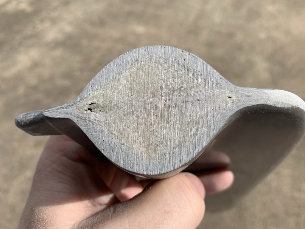
OK, so when we left off, I’d just figured out that the poor fit on the rudder tip was an issue with the counterweight skin shape, not the tip piece itself. So the first order of business was to see about straightening that up. After trying a few more gentle techniques, I decided that I just needed to break out the hand seamers. I suspect that the root of the problem here is that I didn’t square up the flanges on the tip rib way back in 2012 or whatever, which meant that to fix this I needed to target the bend in that area. But a little trial-and-error with the hand seamers got things nice and square, and with that done, the tip piece fit quite nicely.

However, this led to a new problem, regarding clearance between the counterweight area and the vertical stab. Previously, these two pieces were nice and parallel with an even gap between them, but by straightening the upper part of the counterweight, I also caused the leading edge to move downward. Not far enough to actually catch on the stab, but it did result in an unsightly uneven gap, and I still wanted to keep proper clearance here (by which I mean “they’re not touching” wasn’t satisfactory to me). I first addressed this by undoing a bit of my bending, a little at a time, until the gap to the tip when installed started to open up just a bit. Things still weren’t completely parallel, so I removed the rudder and adjusted the rod end bearings. Turning the bottom one in a full turn, and the top one out a full turn, got things looking quite nice.

But at this point I realized I should also be thinking about the rudder base fairing. Just eyeballing things, it seemed like there was an opportunity here for the fairing to interfere with the stab spar head of it…so it was time to switch gears to that piece. This one is a little more fun to fit, because it needs to be notched on each side to allow for the control horns. There aren’t any layout markings or anything provided for this, you’ve just got to figure it out on your own. What makes this even more fun is that the notch isn’t 90° to the upper surface of the fairing.

After thinking this over for some time, I decided to measure things out, using the trailing edge as a reference point. To start with, I identified the distance from the trailing edge to the forward face of the control horn angle, and marked that on each side of the fairing for a starting point. Then I used the width of the lower horn angle to figure out the distance to the other side of the notch, and marked that point on the upper edge. To draw the angled lines, I laid a popsicle stick inside the angle, and used a ruler to draw a line along the bottom of the rudder skin. This gave me a handy sort of angle finder – I just had to align that pencil line with the top of the fairing, then drawing a line along the side of the stick would give me a proper cut line. Then I just had to work out the depth of the angle, and I finally had a starting point for the cutout:

Of course, this wasn’t exactly super precise, and I was conservative with the layout as well, so after making the initial cuts I spent a lot of time carefully expanding the cutout, with repeated trial fitting. I made another sort of fiberglass file with some 40 grit sandpaper glued to a popsicle stick, and really put that thing to work. It took probably three or four iterations on the cutouts before I was even able to get the fairing partially installed. A couple more iterations, and it finally slid into place:

I still wasn’t done, though. The cutout didn’t quite match the horn, and I wanted a nice even gap all around, not like this:

So I marked new cut lines using the horn as a guide, and did even more sanding and such, until I had a nice 1/8” gap all around. I was feeling pretty good about this, and had even started beginning to layout the attach holes, when something (I really don’t remember what) got me to go look up other folks’ work on this. Whatever I was looking for, I found an entirely different concern: seems some folks have issues with the fairing interfering with the tailspring. Additionally, it seems that some trimming might be in order on the leading edge of the fairing. So before I did anything else, I went and tried installing the rudder yet again.

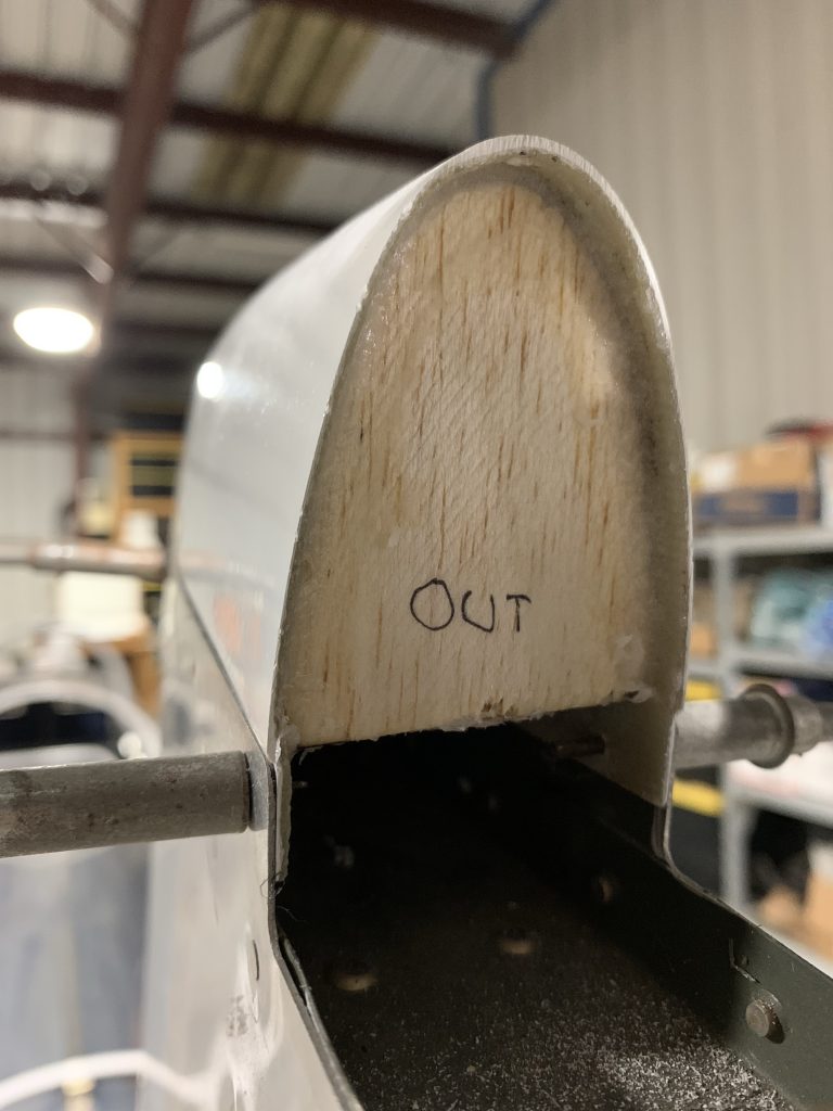
Immediately, the first issue presented itself: the rudder couldn’t possibly go on the way things were now, because the fairing would interfere with the rudder stop attach bolts, as well as the adel clamp I added for routing the tail light wire. In this photo, the rudder needs to go about another inch forward (note that the rod end isn’t even into the hinge points at all):

I needed to solve that problem before I could even see about the tailspring interference. Rather than trying to carefully figure how little to trim off here (read: going through another series of iterations, except this time refitting the rudder repeatedly), I decided to just take the cut along the bottom of the horn forward to the tip. Sadly, this meant that one whole side of each cutout, which I’d painstakingly fit, was going away. Oh well.

For this, I just used a strip of paper to carry the lower cut line around the forward edge, did the rough cut, and then once again did lots of sanding, this time with a long flat block, until the top of the cut was nice and planar. Well, mostly, as seen in the next photo, it still looks like there’s a little upward turn at the front. I’ll have to go clean that up some more, you know, just in case someone gets on the ground and looks across the rudder at just the right angle:

Finally, it was time to install the rudder yet again. Clearance up front with the adel clamp was of course not an issue any more, and the fairing still clears the spar just fine through the entire range of rudder motion. Even better, there’s not interference with the tail spring after all. It’s pretty close – maybe 1/4” if that – but given the location, I think this is probably fine. There shouldn’t be much deflection in the spring this close to the socket – but I suppose I’ll still ask around with the VAF crew to be sure.

Assuming that’s OK, the next thing I need to decide is whether I want to attach this fairing with pop rivets (as per the plans) or with screws. Going with screws might make it easier for servicing the tail light wiring down the road – for example, when the rudder gets pulled for painting. I think it could be just fine with pop rivets – the service method could be to pull the tail light, disconnect the wiring, and then pull the wire from the fuselage forward through the fairing. I’d just have to make sure that whatever anti-chafe I have up front (probably I’ll add a bulkhead with a snap bushing) has a large enough hole to accommodate the plug. Reinstalling would require fishing the wire back through the fairing, which might be annoying but probably not horribly so. But if I go with screws, then the fairing would just be removed and dealing with removing/rerouting the wires would be a lot easier.

At the moment I’m leaning towards pop rivets for simplicity’s sake, but I figure I’ll let that marinate a bit before I make a decision. I might try and fish the wire through the fairing as it sits now just to get an idea how annoying it’d be…though it occurs to me that without the taillight cutout being there, it’d be hard to get a real idea. Maybe I just figured out the next thing I’ll be doing…

Posted in Empennage, Fiberglass | Hours Logged: 6

More vertical tip work

First goal for today was to see about getting the tail light mount cutout done, so I could assess the annoyance of feeding the wire through without removing the tip. Before doing that, I wanted to get rid of the seam line that runs along the length of the tip, including over the light pad. So I got to spend a decent amount of time with 120-grit working that out to a nice smooth surface. But now the bottom is looking pretty nice:

Next up was the light pad itself. The first thing I noticed was that the pad wasn’t actually flat, on each side of the seam it seemed to slop back a bit. So I started hitting this up with 40 grit, but at first did this while holding the tip. This turned out to noe be conducive to getting a nice square face; I had much better luck with the tip clamped to a work table. Unfortunately the result of this was that I removed more material than necessary, and in the process opened up a few holes:

So I decided to do my first real fiberglass layup, to add some more layers of glass here on the pad. Since I figured I’d have some leftover epoxy after saturating the cloth, I decided to also go ahead and prep for adding the balsa insert into the vertical stab tip. The fun part here is that the tip gets spread a bit when clecoed in place, yet I needed the tip off of the stab in order to fit the insert. So I worked up a length of popsicle stick that I could put in the back of the tip to hold it at the proper size even when removed from the stab:

After cutting and fitting the balsa, it was time for glassing. I made a cardboard template using the perimeter of the light pad, which I’d later use for cutting the layup pieces. For the layup, I put the glass and epoxy between sheets of plastic and moved the resin around with a squeegee until the cloth was soaked, then used my template to draw outlines to be cut out. After that, I just needed to peel off the plastic and put the cutouts in place. After adding four layers, I topped it all off with peel ply and left it to cure:

With the remaining resin, I mixed in some flox to make a nice thick structural epoxy, then buttered up the edge of the balsa insert. That got installed into the tip, with a nice tooled bead made around the mating point, and I clecoed it in place to cure overnight. Later, I’ll add some glass plies on the interface for more strength, then fill out the exterior side with micro before sanding it to match the rudder tip:

So that’s it for today – tomorrow we’ll see how these layups turned out.

Posted in Empennage, Fiberglass | Hours Logged: 2

Fiberglass and missteps

OK, that title might be premature, but I don’t think it will be. Let’s just say that my first attempt doing some micro filler work didn’t go so well.

First on the docket was picking up with the rudder light cutout area. Ripping off the peel ply revealed a nice new surface, but with a fair bit of overhang. It probably would have been a good idea to trim that glass a bit before it set, but oh well:

Next up, time to remove all that extra material on the edges and sand to roughly match the profile of the bottom. Since my intent was to cover all of this with micro, I also beveled the edges a bit and sanded off the gelcoat a little ways back. I figured I’d have my micro wrap around to the bevel a bit, and then it could all be sculpted to match later on:

It was somewhere along the line here that I started to think that I kinda jumped into the deep end in terms of glass work. The shape here is kind of complex, especially the small-radius inside curves where the upper/lower edges of the light flare meet the narrower main fairing shape. Even at this point I was thinking it might prove to be challenging to sand this back to a nice shape when everything was said and done.

Anyway, I also pulled off the vertical stab tip and examined the bonded-in balsa filler. My intent with this piece was to add some glass plies on the inside to reinforce the joint, and then use micro to fill out the area between the balsa and the actual tip end, which I could later sand down to match nicely with the rudder tip. I went after the plies first, and that part went fairly well, though working with that stuff in the tight confines was a bit fun. Might have been easier if I’d pre-wetted the glass like I did before, but for reasons I’m not sure about I decided to wet the glass in place.

I almost decided to call it a night right there, but I really wanted to get the micro work done so I could have some cured stuff to work with for my next session. The first comical thing here came when I mixed up a couple pumps of epoxy and then started adding the micro balloons. I don’t yet have a good feel of the epoxy:balloons ratio, though some research after the fact suggests it’s about 1:4-5. The punchline here is that a single pump of epoxy and hardener would have been plenty, with two pumps the mixing cup was getting pretty full after a while. That may be why I decided I had a good dry mixture when, in reality, it needed more balloons.

Once I started applying the stuff, after a bit I started to think maybe it was slightly too wet, but it didn’t seem too bad. The main problem I ran into while working on the stab tip – where I started – was that the stuff really wanted to stick to the popsicle stick I was using, which made it hard to put the stuff where I wanted it. That may have been a poor choice of tool, in retrospect. Once I got the stab tip done, I stuck it in the vise with the open end up while I moved on to the rudder bottom. This was even more fun, trying to put a thin layer of micro on the light face, and then wrap it around the edges. Once again, the way the stuff was sticking to the stick made this pretty tough.

I was still thinking I was doing decent until I finished that and took a look at the stab tip. I hadn’t clamped it precisely straight up, and the micro had overflowed the downhill side. That was when I really realized I made the stuff too wet. I ended up creating a sort of dam around the open end of the tip with tape and plastic, then re-clamping it more perfectly vertical, so I hope that will end up mostly OK. The rudder bottom, on the other hand, I don’t really know of a way to control the flow there, so I’m probably going to end up with something disgusting here when it’s all said and done:

The other dumb thing I did was working on this in the evening during a cold snap. When I went to look up info on dry micro consistency, I also noticed warnings about the epoxy not curing right in low temperatures – and it was down in the 40s by the time I finished up. I set up my heat lamp on these two pieces, which will hopefully help, but who knows whether any of this work will be salvageable. Only time will tell.

Posted in Empennage, Fiberglass | Hours Logged: 2

More fiberglass for the vertical tips

Well, first there’s good news: despite my concern that I’d buggered things up good yesterday, everything turned out just fine. The vertical stab tip ended up actually kinda nice, with the micro just above the level where I’d sanded the glass previously. I knocked that down a bit with a long board and then tested the fit in place on the stab. It’s got some pinholes that will need filling, but I think I’m going to sand it closer to shape before worrying about those.

My real concern, though, was the rudder bottom – but once I got to sanding on that, things started to look pretty decent. Even the relatively complex shape didn’t give me a lot of trouble in the end, though I had to get creative with sanding tools. At one point, I had some 100-grit paper wrapped around a 1/4” docker extension to properly work some of the concave areas. But in the end, all that goop that had dripped down the sides blended pretty nicely into the surrounding shape:

Much like with the stab tip, there are a few pinholes here to take care of, which would just require a little micro. But I didn’t want to mix up a batch of the stuff and only use a tiny amount, so I decided to pick another sizable job – specifically building up the rudder tip to better match up to the stab tip. I marked the general area that needed to be built up, then set to work sanding off the gelcoat in that area to give the micro something to adhere to:

Then I got another batch of the stuff going. Since last night, I did some video watching and got a better sense of what the dry micro should look like, so I added a good bit more balloons to this batch…but I think I might have overdone it a bit. Trying to spread this stuff onto the tip was seemingly impossible, every time I tried to shape it a bit the stuff would form voids, or just decide not to stick to the glass underneath, and the more I worked it the worse things got:

Eventually I just scraped it all off, chucked that batch in the trash, cleaned the part of all residue, and took another go at it. This time I think I made the stuff a little wetter, and while it was a bit easer to work with, it still seems like this stuff is a real pain to work with. After a while I gave up on having anything vaguely resembling a nicely shaped buildup, and instead just went for having enough material in place to shape the thing to near its final state. It looks pretty bad at the moment, but I guess I’ve got to start somewhere:

I suspect that when I get to sanding this, I’ll expose some voids that need filling, but to be honest, I’m not even sure this buildup will be enough to get to the final shape. Roughly, I expect to sand this down to something below the final shape, and then lay on another layer of micro on top to get it to where I actually want it. I feel a little more confident in the results since last night wasn’t the debacle I thought it was.

Oh, and I had enough micro left over from that batch to fill the few pinholes in the bottom as well. Once I sand it tomorrow, I expect it’ll be to the point where I can go ahead and make the mount holes for the tail light.

Posted in Empennage, Fiberglass | Hours Logged: 2

More vertical tip shaping and stuff

Oh, hi. Looks like we just had another one of those dead periods where I randomly get out of the habit of building, and then just as randomly get back to it. At least I’ve kind of gotten used to this ebb and flow after all this time, and I don’t feel super guilty about it any more.

Looking back, I actually have done some work since my last post, but I guess I decided it wasn’t enough to merit an actual post. I say this because I’ve had a partially-sanded ridder tip for some time now; after slagging on that last batch of micro, I went back and started rough sanding it to shape, at which point I saw that it might actually be workable as-is to sand to shape.

Thing was, for sanding to shape I wanted to use the v-stab tip as a sort of sanding guide to get everything nice and even – that is, I’d be sanding the rudder tip with both it and the stab tip clecoed in place – but for this to work I needed a way to immobilize the rudder in the centered position. Normally I’d do this by just clamping between the rudder horn and stab, but having a clamp over the top would block the stuff I wanted to be sanding.

After batting around a number of different ideas, I finally came up with something workable. What I’ve got are a couple pieces of scrap angle, with a hole drilled at one end that gets clecoed to the forward end of the horn, while the other end is clamped to the trailing edge of the stab. With one of these pieces on each side, the rudder is held very nicely in place.

Note: after taking this photo, and before actually working, I removed some material from the forward/upper end of the angles, so they wouldn’t protrude above the edge of the horn skin. Didn’t want that interfering with sanding at all:

Next I applied tape to the stab tip so I could lightly touch it with the sandpaper as I worked without removing any material. Scratching here isn’t necessarily a huge deal, as I’ll be refinishing the tip anyway, but I only want to remove stuff from the rudder. Then I went to town with a sanding block, in lots and lots of iterations. In the end, I was able to sand it down to a nice matching contour, which sounds like good news, but the issue was that I found a number of voids (air bubbles) from when I applied the micro.

These are going to need to be filled, which means more micro, and I want to be careful about sanding two different batches of micro at once.Since mixing micro isn’t an exact science, the density of batches will differ, making even sanding possibly more of a challenge. This is probably something I’m being more concerns about than I need to, but oh well.

Additionally, I’m going to need to add some micro down near the flanges of the tip as well. While everything tucks up nicely at the leading and trailing edge, about mid-chord there’s a larger gap here, which I don’t want. So I’ll be figuring out a way to wipe some micro into this gap as well, which overall means that this tip is probably going to just get an all-over batch of micro.

This photo shows both the matching contour, a couple of the voids, and the aforementioned gap:

Anyway, I decided to make this into a sanding training project first and foremost. Even though I wasn’t going to use it, I spent some time with finer paper refining the contour and getting everything nice and smooth, just so get a feel for what I’ll be doing for real later on. Then I went back to 40 grit and proceeded to remove a ton of micro all over the thing, until the contour was about 1/8” below the stab tip. This is to give me the room to cover the entire thing with a coat of micro that I can then sand down. I also scuffed up the entire surface of the tip for proper adhesion of the micro.

Before I do this, though, I need to figure out how to get everything set up for the flange fix. I’m going to need the tip clecoed in place to pull the fiberglass and aluminum tightly together, but doing that leaves the clecoes really close to where I’m going to need to work with the micro. I’ll also need to cover the area with tape to keep the glass from sticking to the aluminum. I’m kind of tempted to temporarily pop-rivet the tip into place with 3/32 rivets, then drill them out later. I won’t have to worry much about munging the holes in the process, since they’ll need to be opened up to 1/8 for final riveting. Still, that’s a decent amount of work for a temporary assembly…

Next, I moved on th the rudder bottom fairing. Last time I added some more micro here to fill a couple pinholes and build up a couple areas. So this needs some sanding attention as well:

It took me about half an hour to work on these fun little compound curves, and get everything nice and smooth. I’m pretty happy with the overall contour here, so I think I’m about ready to go ahead and cut the hole for the tail light here, and get all the mount stuff taken care of.

 Of course, I’ll also be wanting to probably scuff up the entire piece and shoot some filler primer. Question is, should I do that before or after I cut the hole? Bigger question, am I totally overthinking this? Based on personal history, there’s a good chance…

Posted in Empennage, Fiberglass | Hours Logged: 2.5

More micro on the rudder tip

Short night. After thinking things over from last time, I did decide to go with temporarily blind riveting the tip in place for the next batch of micro. First I removed the tip and applied clear packing tape to the inside of the rudder flange, wrapping it around to the outside to protect the metal surfaces here. Then I poked through the rivet holes and installed my cheap hardware-store rivets. One bit of fun I had from this was that about half the rivets had their stems break off above the rivet head. I was able to trim those off with my flush cutters, to avoid them poking through another layer of tape I put on top of the rivet heads.

Here it is all taped up and ready to roll:

Then I got another batch of micro mixed up. Learning from my last attempt, this time I didn’t try so hard to make the mixture super stiff, in the hopes that it would go on better. Working the mix into the interface gap went pretty well, but trying to put a good layer on top of the tip went about as well as last time. It’s just really hard to spread this stuff out without having it stick to the squeegee and come off the workpiece. I ended up having better results spreading it with a wide popsicle stick, and then I ended up sort of massaging it around with a moistened finger to make things look a little less horrific. But I think I have enough material here to work this down to final shape once it cures, even if it does still look atrocious right now:

Finally, before calling it a night, I peeled off my top layer of tape, leaving a nice clean line at the edge of the tip. This interface should look good with just a little sanding touch-up:

So now I wait until I can sand some more. And maybe next time I’ll try keeping the micro mix even wetter; I think there just still be a middle ground here I’m not finding yet. Though I also kind of feel like trying to spread the stuff on a tight curve like this tip maybe doesn’t help.

Posted in Empennage, Fiberglass | Hours Logged: 1

Shaping the rudder tip

OK, the arctic front is behind us and I can no longer use the cold as an excuse not to go work outside. Finally, it was time to take that globby mess I made last time around and see if I could turn into something nice. I’m starting to wonder if this is just a normal part of the process, that everything looks horrific when the micro is applied.

Anyway, just like last time it took quite a bit of time sanding and checking and sanding some more and rechecking, but eventually (ie after about an hour and a half) I had a nice pleasing shape:

In the course of all that sanding I removed all the major surface voids, but there were still a fair number of smaller air bubbles and pinholes that had been exposed. So for the last part of the night, I mixed up another batch of micro and applied a skim coat over everything to get all those holes filled. While I was at it, I did the same thing to the back of the stab tip, since it had the same issue and I was going to have a ton of extra micro. So this gets to cure overnight and get sanded again tomorrow, then hopefully it’ll be time for filler primer and one last sanding:

Posted in Empennage, Fiberglass | Hours Logged: 2

Shaping the rudder tip again

The odyssey of the rudder tip continues! I’m starting to become amused by how much time I’m spending on this, though I figure future parts work should go much faster since I’ll know better what I’m doing.

Tonight I sanded the tip down yet again, after last night’s attempt at filling pinholes. Unfortunately, by the time I sanded it back to shape, I uncovered…more holes. It would seem that using micro to fill pinholes isn’t the best approach. So I went back and reviewed a bunch of threads on VAF and decided to take a different approach, namely using a few raw epoxy skim coats to fill the holes. This ought to work better since the epoxy will be a lot less viscous and more apt to fill holes rather than just bridging them.

So over the course of a few hours I applied three skim coats, allowing each one to tack up for about an hour before adding the following coat. Hopefully this will give me a nice hard shell that I can sand down (again) to a nice smooth finish and maybe then I can finally spray some high build primer and think about finishing these things up.

In the meantime, things are looking nice and smooth after the third and final coat:

Posted in Empennage, Fiberglass | Hours Logged: 1.5