Electrical

Landing light mounts

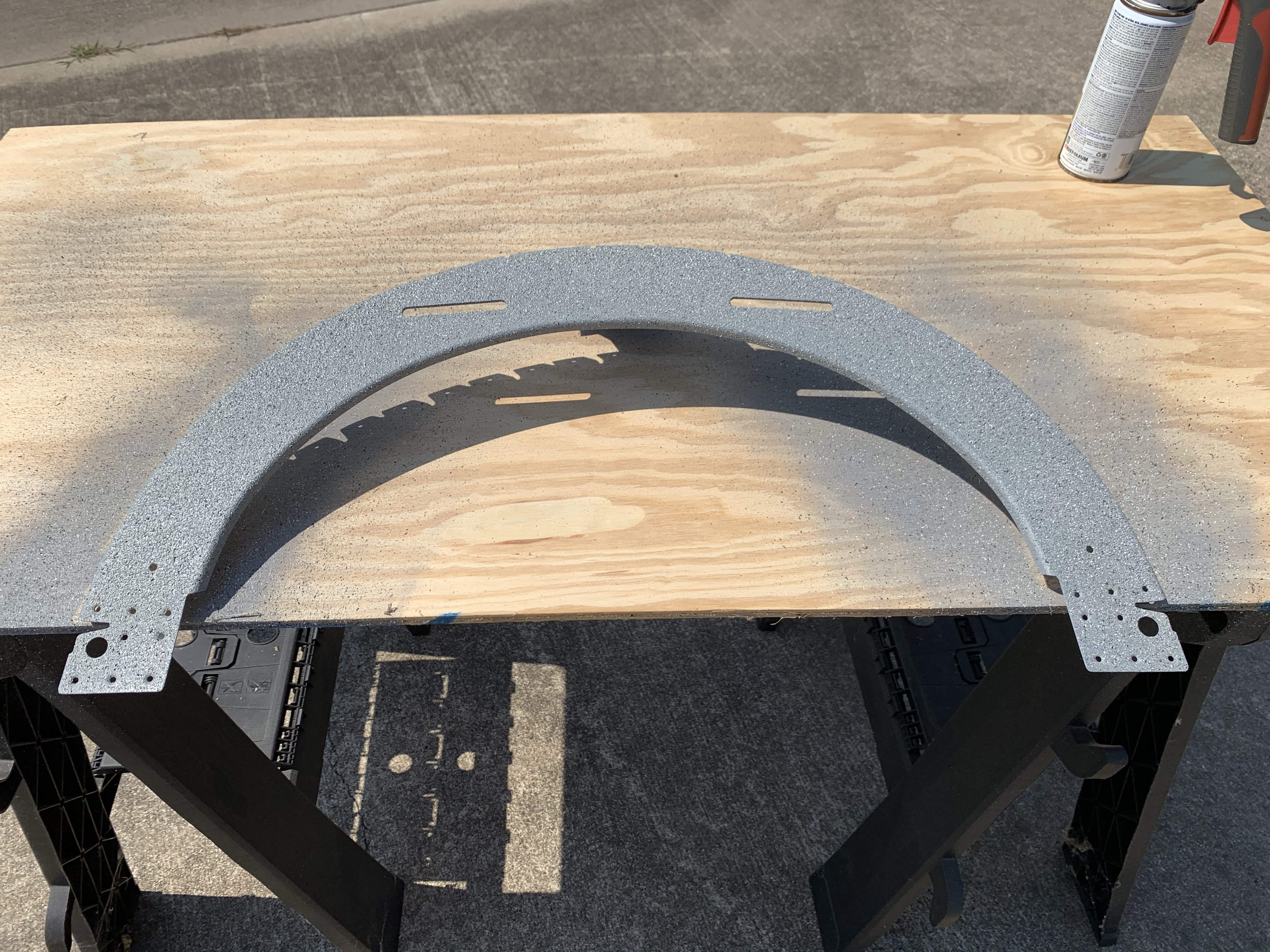
So today’s task was to work out the landing light mounting. Way back when, I bought the Duckworks leading edge landing-light kit, and at that time I’d intended to use some sorta-nonstandard Whelen lights, and so the kit I ordered came with blank mounting plates – rather than, say, having an existing cutout for a PAR36 bulb.

In the intervening years, Flyleds became a thing, and I went with their combo light, which we’ve seen before. One of the nice things about this combo light is that it fits in a PAR36-sized cutout (though the unit is a lot deeper than a PAR36 would be), so it’d work great with that Duckworks mount…if only I had it. And in fact. I did consider just ordering two new mount plates, but in the end it seemed stupid to not at least try to cut the mounts I had.

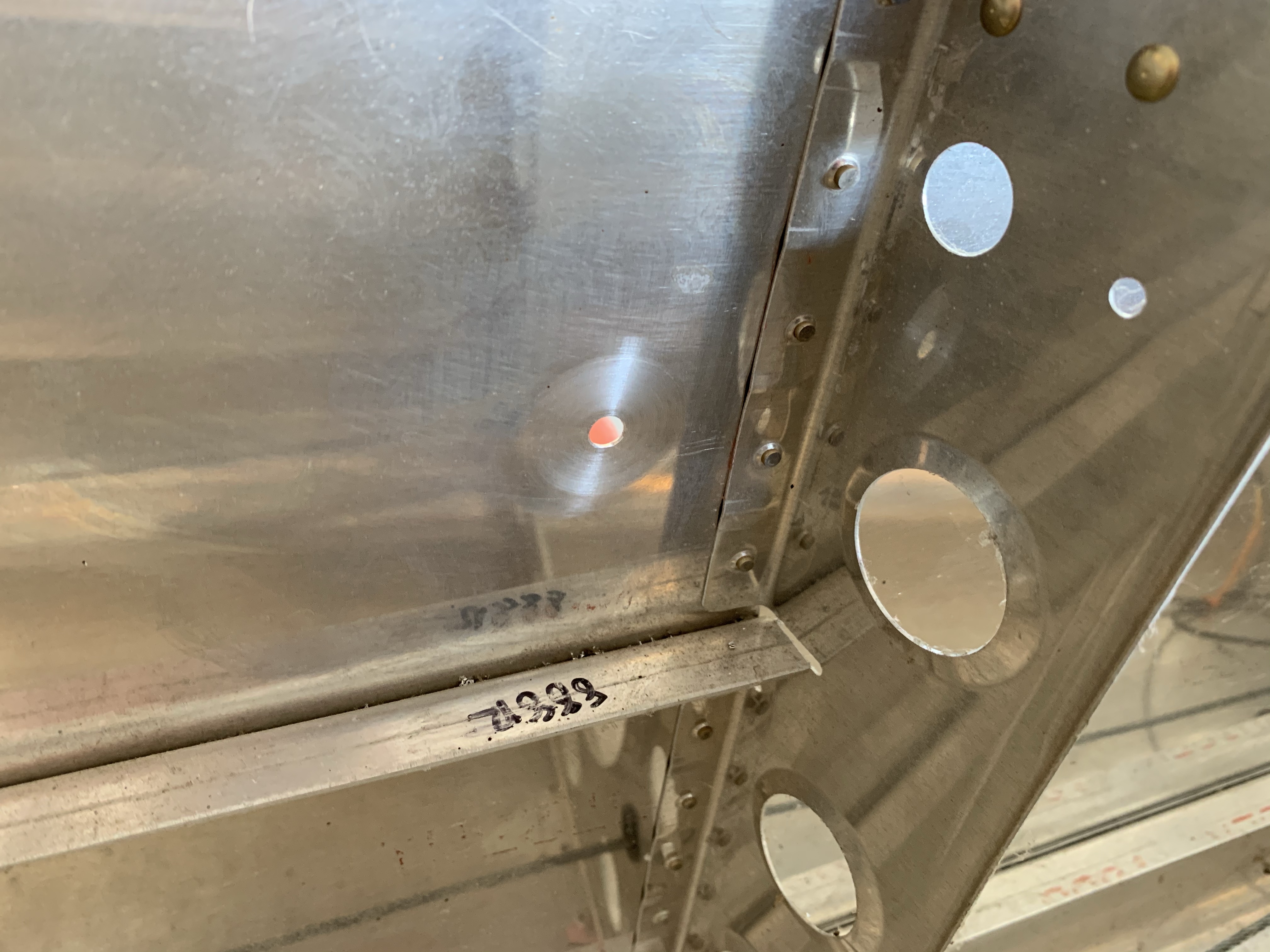
And really, the task is pretty simple. Vertical positioning of the light is a no-brainer – just put it on centerline. The horizontal position is more interesting, though – the mount spans the entire bay in the leading edge, but the cutout is small, so the light obviously needs to be aligned with the cutout. So I spent some time with a ruler, reaching inside the bay, to measure the distance from each rib to the corresponding side of the cutout, and the width of the cutout itself. Armed with this information, I marked off the rough size of the light on the plate – a 4” square (technically it’s round but the square works fine for this). Then I installed the mount in the wing and verified the lineup. Actually, I did this twice, because the first time I measured a bit wrong and put the mark an inch off. Which is, of course, why we start with just marker…

This photo (and a few subsequent ones like it) is a bit awkward – the wings are still in the cart, leading edge down, so I’m basically shooting up from the floor to get this angle. Yeah, I did a decent amount of squirming on the floor today:

With the position verified, it was time to make the cutouts. I actually decided to make these about 4.25” instead of 4”, to provide a little more clearance for some of the components. This ended up being unnecessary, for reasons we’ll cover later, but oh well. My fancy hole-cutter tool, which hadn’t been used in some time, made short work of this:

Next I did some more positioning lines, which allowed me to position a light unit in each mount, and use the prepunched mount holes in the lights as a drill template for the mounts. This gave me my mounting screw locations, and allowed me to cleco the lights into the mounts for the first time:

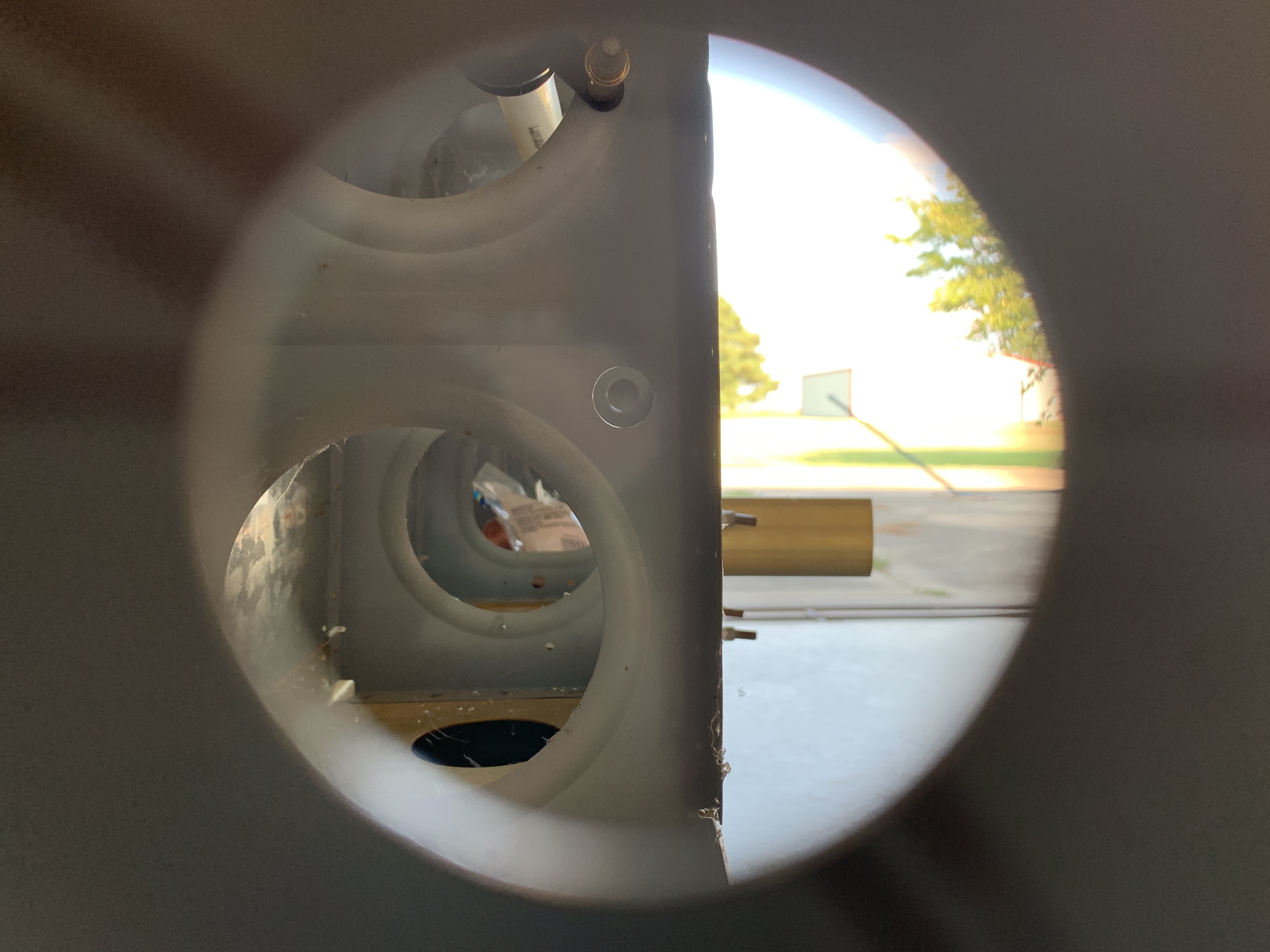
Now, that photo – in particular, the way the lights are located behind the mounts – belies a whole ton of head-scratching. At issue was the question of how exactly these lights would be installed (and potentially removed for maintenance at a later time). Put simply, there seems to be no way for the lights, as delivered, to be inserted into the bay of the leading edge. There are two possible avenues here – in through the leading edge cutout, or through the lightening hole in the outboard rib.

It does seem to be possible to get the unit in through the leading edge cutout, but only with the taxi light projector removed. That would mean installing that thing inside the wing, a somewhat fiddly operation thanks to the long screws and springs involved (that is, the mechanism for aiming the light). I did not like this idea at all, so I decided that I’d plan on going in through the rib. The catch here is that the installation process for these will entail first installing the mount, then installing the light. That, in turn, means that if I’m putting the light in through the rib, it has to go behind the mount.

Still, there was the problem that the light wouldn’t fit through the rib hole either. The useful news here is that while the combo light circuit board is rectangular, the actual circuit traces are confined to a 4” circle. The rest of the board is fair game for trimming to fit a particular application, and that’s exactly what I did.

My original plan was to mark a circle just a bit larger than the mount cutouts, and use that to trim the boards, retaining two “ears” where the screw holes were located. This plan lasted about as long as it took for me to try and figure out how to trace the cut line with a marker. That was challenging enough, but making the cut would be not much fun either. So I decided to start small, and simply mark 45° cut lines starting at my potential mounting “ear” locations. I figured worst case, if those cuts weren’t good enough, it’d be material I’d be removing anyway for the circular cut idea.

Removing the corners still didn’t quite allow the light to pass through the rib, but by simply trimming a bit off the top and bottom of the boards, I was in business. It still takes some careful maneuvering to get the light through, but it’s doable. The resulting trimmed light unit has a sort of elongated octagonal shape:

This just left the question of attaching the lights to the mounts. Normally, if you were installing the lights from the front, you’d install nutplates on the back of the mounts, to receive the mounting screws. That wouldn’t work in this case, so there were two options: either install the nutplates on the front of the mounts, so the mount screws were installed from inside the wing, or install the nutplates on the light itself, so the screws would go in from the front. The latter seemed like a better option: first, I wouldn’t have unsightly nutplates visible in my landing light cutout, and second, trying to line up the screwed working through the lightening hole sounded like no fun.

So I drilled the lights for the nutplates and got them installed, and then, it was finally time for a full-up test fit. First, the mount went in, then the light, and the result looks pretty good:

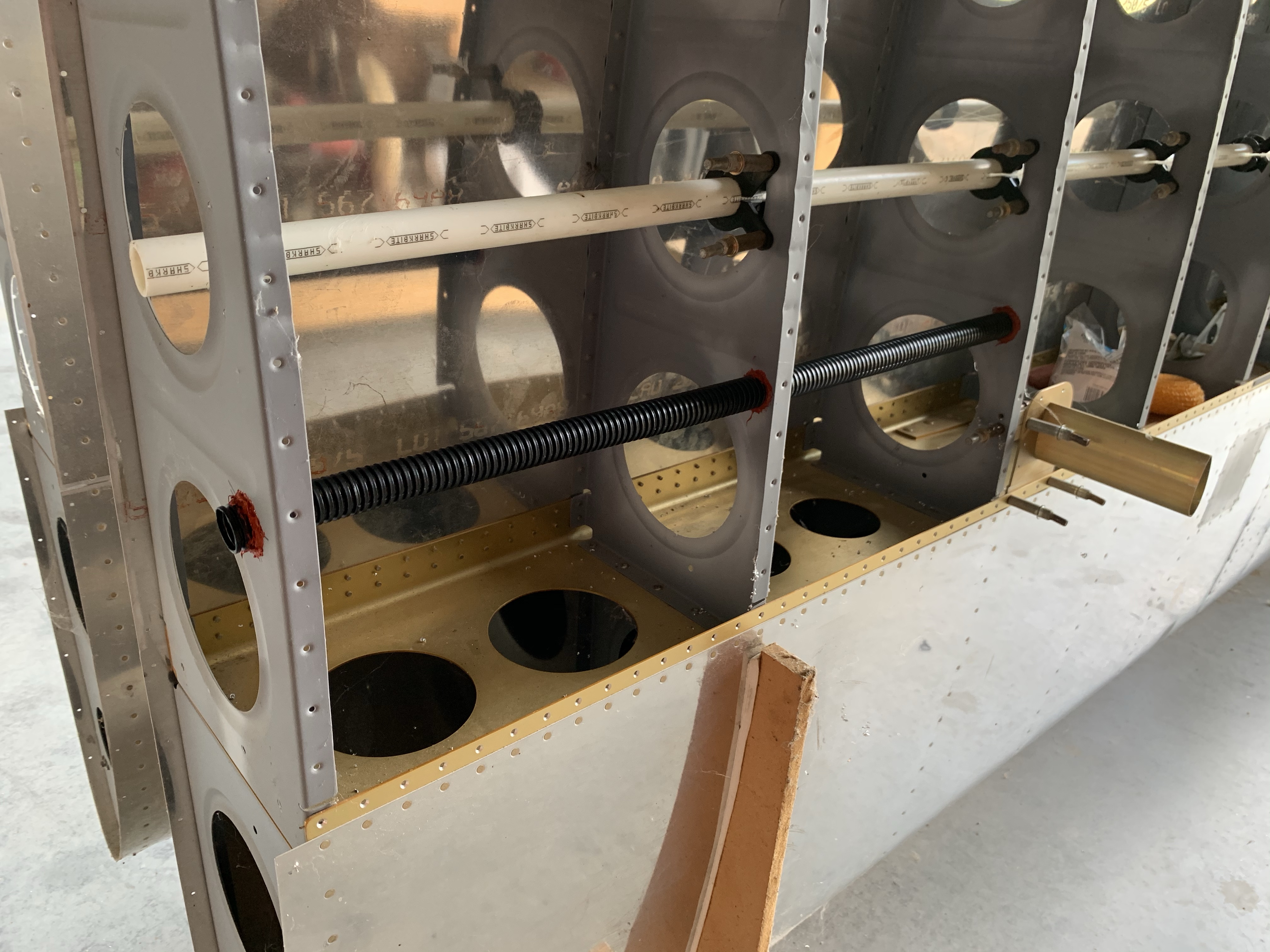
From the back side of the bay, we can see that the heat sinks have plenty of room:

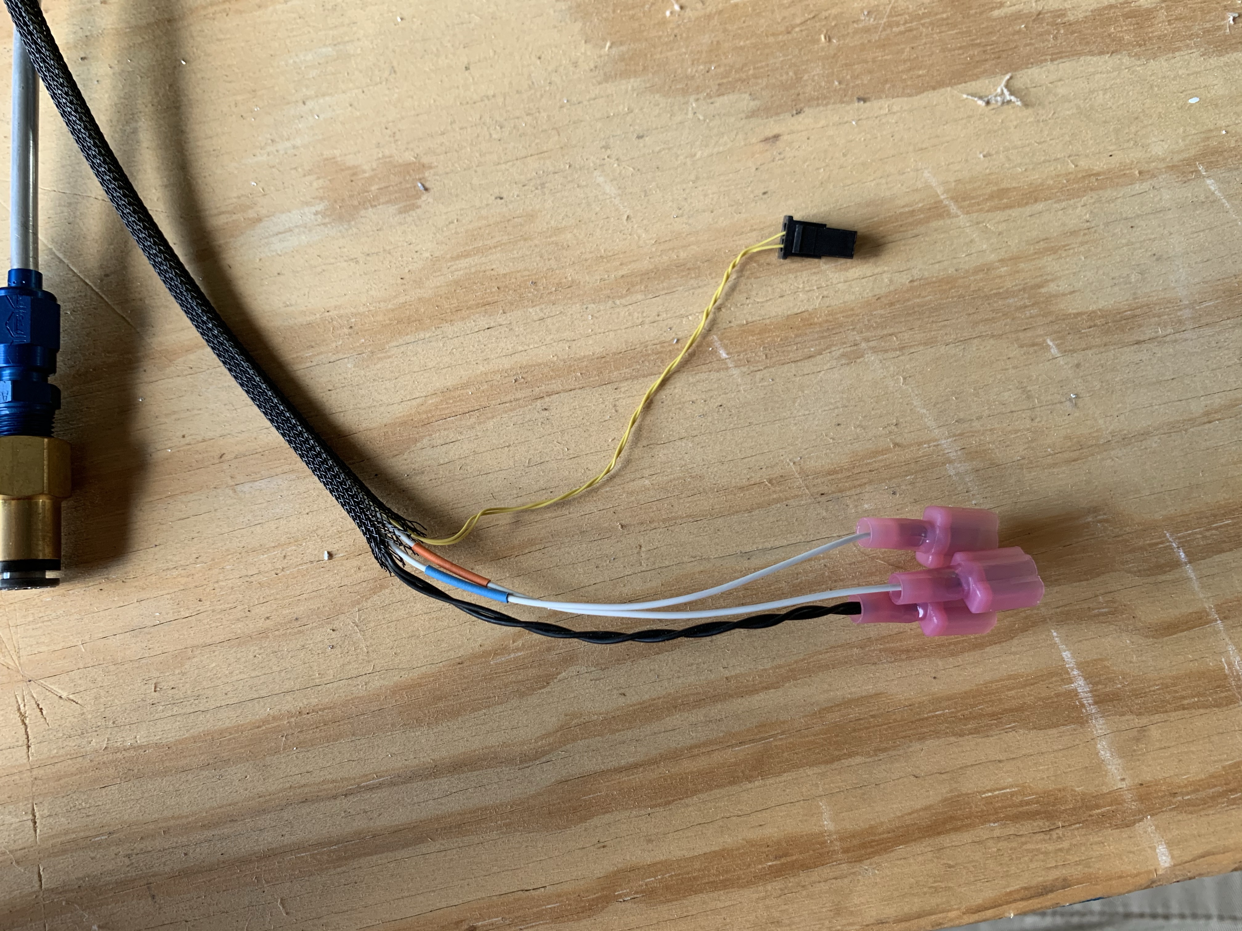
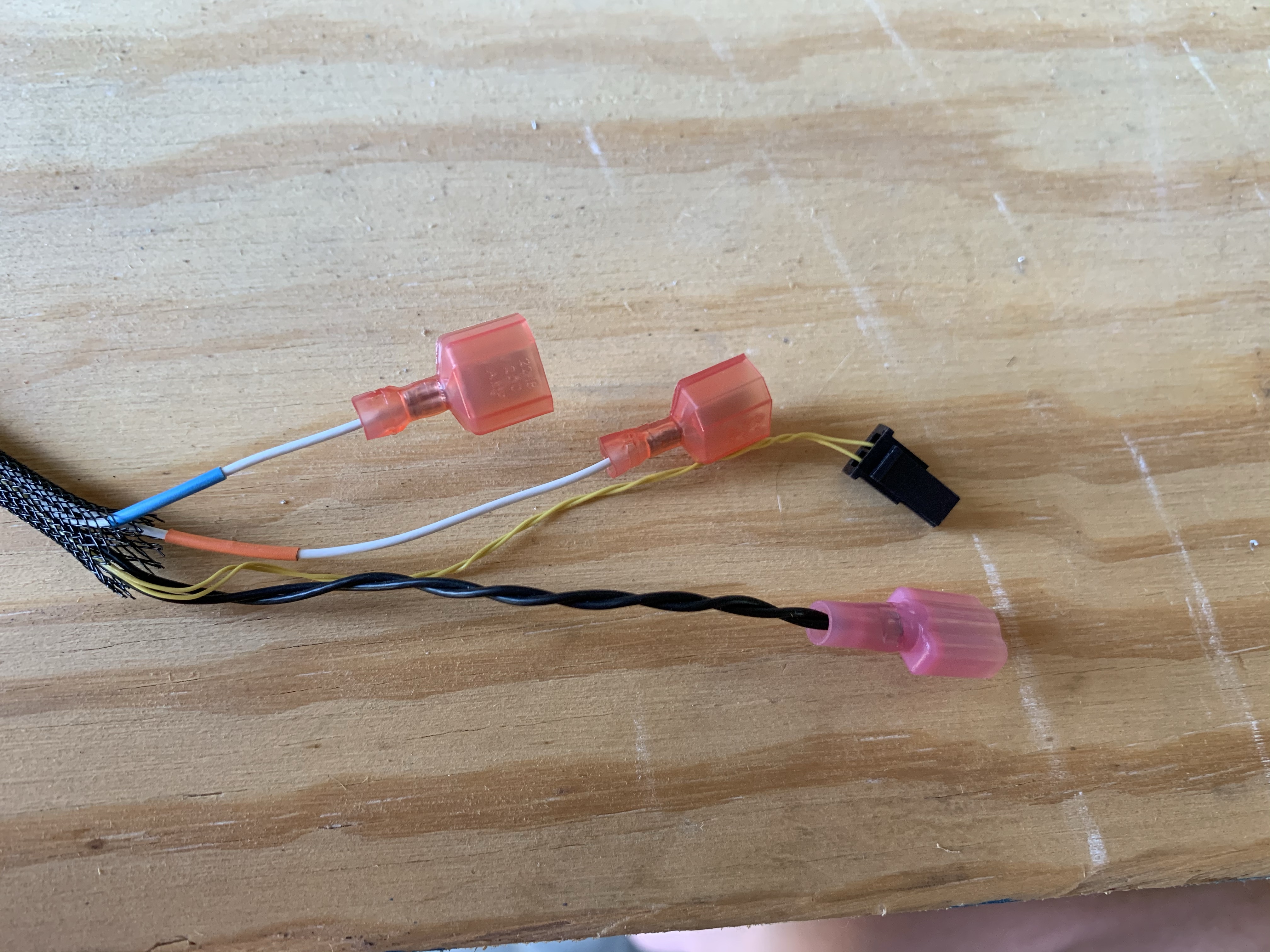
So that’s pretty much the end of this bit. The one remaining question is how I’ll handle the wiring for these; this is particular interesting since the wires for the three landing light projects attach on the front of the unit, while the wires for the taxi light attach on the rear. I intend to run all four wires to a single Molex connecter in the wingtip, and I’d like for the wiring pigtail to be removable along with the light unit; so I may have to get creative with that. Worst case, i guess I could just use two two-position connectors instead of a single four-place. In any case, I can’t really do anything with this until the wire comes in.

So now I guess I gotta figure out something else to do that doesn’t involve wire. Maybe I should dig up the aileron trim servo and see about getting that system done; I worked on that years ago, got frustrated, and moved on. Perhaps I’m better skilled now than I was then…

Posted in Electrical, Wings | Hours Logged: 4

Staring at things

I’ll tell you, the more time goes by, the more I really come to understand the whole “90% done, 90% to go” maxim among builders. In my mind, I have a whole roadmap of things to be done, mostly revolving around getting the wiring done. Yet every time I go to try and move forward on that, it seems like there are myriad little hangups preventing forward progress.

As of today, I’ve received all the wiring stuff I ordered. A whole lotta wire in various gauges and colors, an absolute boatload of D-sub components from SteinAir, plus the relay and diode I’ll need for tying the busses together. The general goal of this was to be ready to permanently install the conduit runs in the wings and get all the wiring pulled, and specifically the first thing I wanted to address was getting the pitot heat controller installed with its extended wiring harness.

And yet…after thinking about how to run the wiring from the controller to the pitot location, I’ve decided the smart thing to do would be to put in a short run of split loom conduit from the wingtip to the pitot bay. If I were to ever need to replace that wiring, this would vastly simplify the process. It also provides better wiring protection, and finally, enables me to satisfy a concern I had about the wiring service loop.

I’ll need enough slack in the wiring to allow the pitot to be removed from the mount until I get to the preinstalled disconnects. But with no good access to the pitot bay, the best I can hope for is just cramming the wire in there and having it floating around unsecured. It’d probably be OK, but the thought bothers me. With the conduit, though, I can keep the service loop normally at the wing tip, where I can secure it carefully. If I need to remove the pitot, I can just feed the extra wire into the conduit, providing the slack needed at the mount.

The downside is that, well, I need some conduit before I can move forward on that. The good news is that I can get that from Amazon and have it here early next week with free shipping. But it’s still a wait…

That brings us to the next hangup of the day. This started with me thinking about the holes I’ll need to cut in the fuselage sides to allow the main wiring conduit to protrude inside, but that moved into a different question related to the pitot tube. I’ve been planning on running the nylon pitot/AOA lines though snap bushings in the ribs alongside the main spar. But then I have to figure out how to get them into the fuselage. I can’t just make penetrations right in line with the line locations, because on the fuselage that’s where the spar center section structure lives. There’s an existing hole nearby, but that’s where the aileron push tubes pass through…routing lines through there seems unwise. So if I stick with location, I’ll have to route the lines in the tight space between the wing root and fuselage aft to some sort of passthrough.

The more I think about this, the more I end up back at my original plan, which was to route the lines through the wiring conduit. Then it can enter the fuselage at the same place as the wiring, thus simplifying everything quite a bit. Additionally, the lines can exit the conduit at the wingtip, and go through the same flex conduit as the controller wiring, and have the same service-loop securing setup as the wires. That has a nice tidiness to it.

The question just remains: how well will everything fit? Well, at least I now have the materials needed to make that evaluation. Something for tomorrow’s to-do list, I guess.

So that brings us to the one bit of tangible work for the day, though there’s an amusing twist at the end. This returns us to the question of making the fuselage penetration for the main conduit. A while back I came up with the idea of making a template that I could use to locate those holes, and tonight I decided to put that into practice.

Basically, the idea was to locate the conduit relative to the bottom of the aft side of the spar. This wasn’t too hard, just required some careful work with a try square, ruler, and other fun stuff. I then transferred my measurements to a piece of scrap 1×4, and drilled a #30 pilot hole. I figured I’d eventually use this to drill a pilot hole in the fuselage, which I’d then enlarge with a unibit.

With the pilot hole drilled, I did a visual test against the conduit bracket on the inboard rib, and it seemed to line up well, so I added the last piece: another scrap 1×4 piece screwed 90° to the other one. The idea is that this piece is slid into the center section and held against its aft side, providing the reference needed to locate the hole.

Here’s the finished piece, sitting by itself and then held in place on the fuselage:


Now, for the amusing twist: I’m not sure I’m going to use this after all. After attaching the 90° piece, I did another sort of test-fit against the end of the wing spar, and then it seemed the hole wasn’t lined up well at all. Granted, this is probably because I had to hold the piece much further from the conduit bracket, but that just made me think that there’s a lot of slop in this setup, and so my overall trust in it is pretty low.

I’m thinking that just figuring out a measuring scheme I can transfer to the fuselage is smarter. Maybe first measure the distance from the bottom of a wing rib to the bracket center, ensuring I’m square against the rib when I do it. Then I can make on the rib where the line intersecting the bracket hits the rib, and measure the straight-line distance from that to the intersection of the rib and the spar. That should be easily transferable to the fuselage, and seems more reliable than my template idea, which kind of feels like the old telephone game where intermediate reps end up garbling the original message.

I’m also thinking now about just seeing if Josie can help me…well…very temporarily install a wing on the fuselage. This would have a couple benefits: I could then run the conduit through the wing in question and directly trace its outline on the fuselage, and have a lot more confidence in the hole location. I could also measure the clearance between the inboard rib and the fuselage at that location, which would help me trim the conduit to final length, and thus eliminate a source of trial-and-error when the time comes to more permanently fit the wing.

Will I do it? I dunno, we’ll see if I still feel positive about the idea after a good night’s sleep. Though first I guess I’ll be finishing up my Amazon order…

Posted in Electrical, Wings | Hours Logged: 2.5

Mostly more staring

Once again, it’s been one of those days when all the effort seems to be mental, and very little happens from a physical standpoint.

One note from yesterday: after doing some reading, I decided against my idea of temporarily mounting the left wing so I could locate the conduit penetration. Sounds like that would be at least a three-person job, and I’m not sure the benefits would justify the effort and risk – besides, I don’t think there’s real reason to do it right now anyway.

To start the day, I decided to evaluate my idea of going back to running the pitot lines through the conduit, and I did this in the most practical manner possible – by cramming examples of the wires I’d need into the tube, along with the pitot lines. Here I’ve got two 12AWG wires (power/ground for the pitot), one 22AWG (pitot heat status), two 18AWG (landing/taxi light power), and the big shielded wire for the nav/strobe light units. It all fits quite nicely, so I declare this idea to be feasible. This at least settles one packaging concern.

Next, I moved on to looking at the pitot controller. I still can’t finalize the wiring run to the pitot location until I get some supplies, but I figured I could at least work on the connectors a bit. One problem here that had to be solved was with the two 26AWG white wires that go from the controller to the tube. These twisted pairs end in Molex micro-fit connectors, and a couple weeks ago, while trying to clumsily de-pin one of them, I pulled the wire out of the contact. I ordered a proper removal tool from SteinAir, only to find that apparently I need two of them to de-pin, since each pin has two tabs, and the tool only has one prong.

I’d already ordered the necessary parts a while back, including extras, so I just decided that I didn’t need to de-pin after all. I just cut off the old connector, crimped on two new pins, and installed them in a new connector. Done. Also good practice for when I build the intermediate harness later on.

Also, while I was in a crimp experimentation mood, I decided to give my D-sub crimper a try. I cut off a small length of 22AWG and grabbed pins, sockets, and a connector for good measure, all from my last SteinAir order. Crimping the pin was super easy, as was inserting it into the connector with the insertion tool I got from Amazon. Extracting it was a different story – turns out buying this tool from Amazon was a poor choice. The extraction end is malformed and unusable. So now I have a test pin inserted into a connector and I can’t remove it. Fun.

This pretty well transitions into what I spent the rest of the day doing, and that was compiling yet another round of orders. I knew I wanted a actual non-crappy D-sub pin tool from Stein. I also wanted to order the conduit from Amazon that I was looking at last night. Oh, and I wanted some cushion clamps to use for routing the wires at the wingtip, once I had all the materials to actually mount the pitot controller.

And of course, since I was ordering stuff, I wanted to maximize the utility, so there was lots of looking forward to other wiring stuff and adding items. In the process, I sort of firmed up my plans for components under the seat pans – mainly terminal strips for interconnects to wing wiring stuff, but also rough location ideas for the Flyleds controller boards for the nav lights and the landing light wig-wag function.

Now I just need to go actually complete these orders. The real question is, how many days will it be before I realize I need even more things? Also, how much of the cost of building this plane will have gone directly to UPS and FedEx? I don’t want to know…

Posted in Electrical, Wings | Hours Logged: 1.5

Paint, static ports, and conduit too!

Nice productive day today, on a variety of stuff, even though I found myself needing things to complete some tasks. First up was getting the remaining bulkhead cleaned and scuffed for priming, then left out to dry while I went across the runway for coffee and chit-chat. By the time I came home, it was good and dry, so I got it primed. An hour or so later, with the primer dry to the touch, I went ahead and shot the stone texture coat, which I then left to bake in the sun. Apparently the heat and sun really help this stuff cure – previously I’ve found this paint to still be smearable a day later, but this time it was dry to the touch by mid-afternoon. It was actually dry enough that I went ahead and clecoed it in place in the fuselage, though I’m still going to wait until probably next weekend before doing any riveting, just to be sure.

Hey look, paint!

So with nothing more to do on the bulkheads, I needed a new task, and I decided to get going on the static ports. This ended up being a prime example of how vulnerable I can be to “analysis paralysis.” Before doing anything, I went inside to just look at some static system install photos, and ended up reading a whole lot of discussions about issues with static ports.

To preface this conversation, the plans method for static ports is, in the great tradition of Van’s, dirt simple – you just remove the stem from a pop rivet and bond it into a hole, then stick a tube on the inside portion. This is a touch crude for me (and others), so some time ago I bought a kit from SafeAir1 that included machined static port inserts.

Thing is, some people have reported airspeed issues with the SafeAir1 ports. From further reading, I learned that the first kits sold placed the static ports flush with the fuselage skin, unlike the pop-rivet method, which would put the ports slightly proud of the skin. Fortunately, later kits remedied this and left the ports similarly proud, and this is the type of port insert I have. Of course, there were still people reporting airspeed issues with those ports as well. Some people went so far as to install the port inserts on the outside of the skin, but still other people opined that this might cause errors due to being too proud of the skin.

Long story short, I could have spent all day trying to figure out the exact right way to do static ports, but in the end I was able to just go and install the ones I had. It seems that if I end up having any issues, they can be addressed a few different ways, so in the end I just did the thing.

Van’s says to place the ports four inches below the longeron rivet row, and one inch forward of the adjacent bulkhead row. Since the flanges on these inserts are larger than the plans pop rivets, I moved the hole an additional quarter-inch forward, to ensure clearance with the bulkhead flanges. After measuring a few times for good measure, I drilled the 1/4” holes, one on each side of the tail.

then there was the question of how to mount these. Some people rivet them, one people bond them, some people who really like to combine belts and suspenders do both…I decided I was just going to bond them. If it’s good enough for my fresh-air scoop forward, it’s good enough for this. So I scuffed up the mating surface of the inserts, as well as the mating area inside the skins:

Here, though, I hot a roadblock: I don’t have any epoxy on hand. So much for bonding these today. I actually considered going out to buy some, but that seemed like an unproductive choice, especially since I’d probably have to go into Katy to find anything. Instead, tomorrow I can just run into Brookshire when the hardware store is open.

OK, so what next? I know, I can finally install the conduit that took me three tries to buy, and work on the pitot tube heat wiring. First up was locating the conduit holes; I reviewed the Van’s guidance on placement, which OKs a location between the forward most lightening hole and the adjacent one. I picked a center location that provided good distance between the rib edge, the lightening hole, and the stiffening ridge between the holes. I was initially going to make some sort of a jig so I could locate all the holes in the same place, but had a better idea, just using the intersection of an arc drawn off the hole, and a straight line off the rib edge.

With the holes located, I drilled pilot holes and then busted out the Unibit to open them up to 3/4”:

Then I measured the conduit run (about 24”), cut off some conduit with extra length for good measure, and pulled it through the holes. I see some people report having a lot of trouble doing this when they use this for wing wiring, but I found it pretty simple to pull through. The key is to stretch it was you pull, making the outside diameter shrink a bit so it goes through the hole more easily. I pulled the conduit relatively snug between the ribs so it wouldn’t sag, which should make running wires easier. Finally, I applied RTV around the conduit on each side of the rib penetration, to stabilize it in place and prevent vibration from cutting the conduit:

All right! Next I’ll locate the pitot controller and drill its mounting holes…wait, that’s a bad idea. I’ve got wet RTV down there, probably not a good plan to do drilling above that and embed aluminum chips in the RTV. OK, we’ll move on to wiring instead.

Since I’m extending the wiring between the controller and the tube, I’ll be adding an extra pair of terminals, which will need to pass cleanly through the conduit. This is particularly important, since my plan for dealing with the service loop of wire and pitot line will be to pull the slack out to the wingtip and secure it there (as opposed to letting it just sit loose in the wing bay).

Problem is, as supplied, the terminals both on the controller and tubs sit right beside each other, which would make for a very bulky spot in a snug conduit:

So I basically re-terminaled both the controller and pitot harnesses, staggering the wire lengths, which will allow the whole bundle to be slimmer. Once it’s assembled, I expect to wrap both joints in silicone tape or something just to help smooth them out even more. Here’s the same harness from above after trimming:

OK, now the RTV is pretty dry, so let’s get that controller located. To make this a little easier, I transferred the shape of the controller base into thin scrap plywood and thus made a template. I used the template to locate the first mounting hole, checked the actual controller in place with that hole, then used the controller itself as the template fo the other three holes. I considered going ahead and putting in the nutplates here, but for the moment I think it’s actually easier to use clecoes to temporarily mount the thing. Here it is with the two wiring runs roughed up: the feeds from the wing root coming out the white PEX conduit, and the harness going to the pitot tube going into the black ribbed conduit:

Finally, I had everything in place where I could make the extension harness that will go through the conduit! Well, actually not, it turns out. I only have red and black wire in the gauge needed for this run. Black isn’t an issue, since that’s the actual color of one run, but the other two are blue and orange. I’m not OCD enough to need the colors to actually match for those, but I do want to use an acceptable generic color, which is white. Red implies a power run – which these are, in a way, but I don’t like the ambiguity. I’d rather match the wires on the pitot tube harness, where there’s one black wire, and two white ones with heat shrink color-coded to match the controller wires.

So yeah, I need to order some wire to make this extension harness. And I guess colored heat shrink as well, but that I already found on Amazon, so that’s easy. Not sure where I want to order the wire from, I think I’ll be figuring that out tonight.

Hopefully tomorrow I can get those static port inserts bonded; if so, then I can go ahead and get the static line routing in place between the two ports. Just one more little thing.

I’ve also been thinking about my other conduit runs in the fuselage. I think I’m going to want two runs under the seat floors: the right side can house the wiring harness going to the aft avionics bay and tail, and the left one can route the pitot and AOA lines back to the ADAHRS. The other fun thing is the conduit I’d intended to run in the tail; if I run it through the holes I originally planned, it’ll exit into he baggage area, which I don’t want. Instead I think I’ll end up with a curved run, starting low in the bell crank area and ending up high at the tail. The challenge here is that the conduit run will go around a longeron, and I’ll need some way to keep that contact from wearing through the conduit over time. I’m not actually sure that this idea will work…another thing to think about…

Posted in Electrical, Fuselage, Wings | Hours Logged: 3.5

Pitot harness

Built out the pitot heat extension harness tonight. Unfortunately, the end result wasn’t quite what I’d hoped for, as we’ll see later.

I ordered wire like I mentioned previously, and it came in today. Unlike what I said before, I ended up ordering orange and blue wire instead of just white; the price was basically identical to buying white wire and colored heat shrink, and I figured having some spare wire around was slightly preferable to a whole set of colored heat shrink that I’d probably never use.

Anyway, this was pretty straightforward. I’d previously determined the length of the extension harness as 30”, so I cut the required length of black, orange, and blue wires, and crimped on the required terminals. That left the two tiny-gauge sensor wires; for these, I decided to twist the pair together to help facilitate keeping things neat. Then the small wires got micro Molex pins/sokets, and were installed into their connectors.

Finally, I connected everything to the controller harness, bust out my lacing cord, and bundles everything up. Not strictly necessary, but this should make it easier to feed this through the conduit when required:

Next up was a trial fit in the wing. What I’d hoped to do here was to run both the harness and the pitot/AOA lines through the conduit together. Well, the harness goes through OK, and the lines can be squeezed in there too, but already there there’s an issue: things are pretty tight, like I can hardly pull slack on either the tubes or the harness without dragging something else along. Worse yet, there’s no way to pull through the connector bundle at the tip rib, which is a requirement for getting enough slack at the pitot mount for servicing.

Yeah, it’s kind of tight:

So long story short, running the harness and tubing together seems like a non-starter. Looks like I’m back to routing the lines through snap bushings in the ribs instead. I’m also seriously considering adding another access cover beside the pitot tube to facilitate maintenance. I don’t especially like the idea, but I’m no longer 100% convinced that all my ideas for promoting serviceability are going to work. I think I’ll do one final experiment before going with that – clenching the wing skin in place, and seeing just how hard it is to reach in and over to the pitot bay if it were to become necessary. I think it’s doable, but maybe not preferable.

Posted in Electrical, Wings | Hours Logged: 1.5

Lower shelf

Did some more messing around with the lower shelf tonight. After putting the bulkhead and other stuff in place previously, I was able to measure more precisely the width I could make the shelf, so before moving to any fabrication I cut down my cardboard mockup and did yet another dry run of component positioning. This time I made it a little more realistic by laying some of the cable guides I got in place to better simulate the wire runs. I even went so far as to estimate the size of the bundles that will come off the fuse blocks because sometimes I get carried away like that.

The general idea here is that the two supply lines (one switched, one always-hot) will come in from the top left. Switched line goes to the main bus on the left, always-hot goes across to the battery bus on the right side. From there, one supply line will tap off the main bus, across the diode, and to the e-bus; a similar supply line will tap off the battery bus, through the relay, and act as the redundant supply for the e-bus. That feed will be switchable from in the cockpit if necessary. All the individual circuit feeds will be routed together at the bottom and exit at the top right, along with the switched ground for the e-bus relay.

I also rethought the hinge setup for this shelf. Previously I was thinking of using a piece of angle to space the hinge point off the bulkhead a bit, to allow for clearance to the brake lines while the shelf was lowered. Doing the layout work above made me question the wisdom of losing 3/4” of width on the shelf, though, so I decided to retain the hinge point against the bulkhead, and just come up with some means to limit the travel of the shelf when lowered. This can be done rather simply, it turns out – I’ll want to add stiffening flanges on either end of the shelf, and if I orient them downward, they can act as travel stops when they hit the bulkhead. I’ll probably eventually add some rubber or other material on the edges just so it’s not metal-on-metal, though it’s probably not a big deal.

Anyway, tonight I started fabricating the shelf. I cut off yet another section of that old wing skin, trimmed it to rough size, and also cut the piece of piano hinge. I actually ended up stopping at this point, because I want to carefully lay out the stiffening flange, seeing as how it will be acting as a travel stop. I’d like to be careful here, so I can get maximum travel out of the shelf (to provide the best accessibility) without hitting the brake lines.

So I’ll work that out, and then I can probably finish fabricating this thing in pretty short order.

Posted in Electrical, Fuselage | Hours Logged: 1.5

More lower shelf

Just more poking with this shelf today. I made myself a little diagram and spreadsheet to analyze my idea for letting the shelf flanges act as a stop. Turns out it’s not really a workable idea, unless I want to get really fancy with those flanges…which I don’t. So I changed my mind (again). I’m going to bend the flanges up at the edges of the shelf, which will make the bottom smooth, and just let it rest against the brake lines when it’s lowered. Since this will only ever happen on the ground, I think this is fine.

This decision was the culmination of a variety of head-scratching moments today. At one point I put the baggage bulkhead and other associated parts back in the plane to evaluate how the shelf would sit. I did actually do a tiny bit of metalwork…I took a vixen file and squared up the cut edges of yesterday’s sheet, then got the flanges laid out. I wanted to get to cutting them, but the hangar lights were attracting entirely too much insect life for my liking, so I used that as an excuse to go inside for the evening.

Hopefully soon there will be some photos of the result of all this head-scratching. But probably not tomorrow, the grass is looking like it’s due for a mow, and sunset is getting earlier by the day…

Oh, I did get in my big pile of switches and stuff from Digi-Key. Once this shelf is fabricated, I think I might be moving on to the switch console.

Posted in Electrical, Fuselage | Hours Logged: 1

Almost done with that pesky lower shelf

So yeah, made good progress on the shelf tonight. First order of business was working on the other half of the piano hinge, which attaches to the lower baggage bulkhead. I already had my layout lines there from a previous session, so this went pretty quickly. About the only real challenge was that since the hinge half is pretty much in the middle of the bulkhead, there was no good way to clamp it in place for the first few holes. I just resorted to holding it by hand while drilling the first three holes, then with it checked it was in a good spot to drill the rest of the holes. Then I just did all the demurring and prep and riveted it on. Nothing to it.

Next up was dealing with the attach point for the aft end of the shelf. I’ve planned all along to handle this by attaching aluminum angle to the aft upper brace, and the projecting lip of the angle is where the quarter-turn fasteners will live. I did change that plan up a bit, though – originally I was going to have the free side of the angle pointing forward, but I decided to reverse it instead. The reason for this was to provide more room on the shelf – with the angle forward, I’d have about 3/4” of the shelf where I couldn’t really run anything. Turning it the other way gets me that space back.

I’d also originally planned to use a single piece of aluminum, but I decided to do the extra work necessary to just have four small pieces in my fastener locations. Might as well save a little weight here and there.

Laying out the angle was a bit more fun than the hinge half, especially since I was working inside the fuselage and not on the workbench. Plus, messing up the brace would be annoying, so better to be careful here. Here’s a look at the brace with the four angle pieces clecoed in place:

Next up, it was time to reinstall all the baggage compartment pieces. In order to really make that bulkhead stable, the baggage floor has to be in place too. So a bit of busy work there, but once that was done, it was the moment of truth: trying to install the shelf. I probably didn’t need to worry, it fit just fine.

Here’s the shelf clamped into its stowed position (also giving me my opportunity to mark where the shelf edge should go, using the angles as a guide):

And then in the lowered position, as I’d see it if I needed to swap out a fuse or service anything else here:

So we’re getting there. The big remaining thing is going to be fitting the actual quarter-turn fasteners. These things came with no instructions or drill templates or anything like that, so while they’re not exactly complicated, I’ve still got to get this hashed out. Maybe I should check the McMaster website and they’ll have some dimensional drawings I can us for drilling.

I’ve also got to get those angle pieces primed before I install the fastener bases and rivet everything in place. I’m leaning towards just using MSP blind rivets here; bucking under that brace might be interesting, especially with the bases installed. But the way I figure it, this should be wrapped up tomorrow.

Posted in Electrical, Fuselage | Hours Logged: 2

Wrapping up the lower shelf

Hooray for shelves! OK, I didn’t finish them yesterday like I thought, but that’s cause I ended up not doing airplane things yesterday. So I maintain that this counts, you just have to interpret “tomorrow” as “the next workday.”

The first part of the day was just figuring out how to get these quarter-turn fasteners installed. I attempted to find some documentation for these Friday night, and about all I ran across were some engineering drawings. So I did some mocking up and tinkering today just to wrap my head around how these should work. The overall idea is obvious: two rivet holes to attach the base to its mounting surface, and one larger one in the center to accommodate the actual fastener.

What’s interesting is that the specs on McMaster-Carr seem to indicate that the center hole should be a different size for the two panels – but that makes no sense, as the fastener has to go through both panels. So I just started experimenting with scrap. A 1/4” hole was a good size to accommodate the fastener shaft with a bit of wiggle room.

Next up was how to actually locate that center hole. I couldn’t just use a base as a drill guide, since the center hole isn’t really round. Instead, I worked out the rivet hole spacing, and just made myself a drill guide using a piece of scrap angle. With this, I could drill three #40 holes in a piece, then enlarge the center hole to 1/4”. I did a test run drilling a set of holes in another piece of scrap angle, and it worked perfectly.

Next I drilled a 1/4” hole in a strip of sheet, and used the fastener to attach them. This worked, but didn’t hold the pieces tightly together. This wasn’t automatically an issue, though; in practice, there’s a little retainer that goes on the fastener, which is what keeps it captive in the panel. I measured one of those and found that it was .040” thick. Just right for me to use a piece of scrap hinge as a pseudo-retainer to test the final fit. (I couldn’t just use the retainer; they’re a one-time use thing, and I had no spares)

So finally, after probably an hour and a half, I was satisfied that I could actually mount these things. Next I had to actually fit them. The challenge here was accurately drilling the center hole in assembly between the shelf and mount brackets, in position in the airplane, clamped together tightly. What I ended up doing was first laying out those holes in the shelf. To do this, I installed the shelf in the plane (for, I dunno, the fourth or fifth time) and marked the outlines of the four brackets. Then the shelf came out again and I marked the counterpoints for each bracket, then drilled a #40 hole at each spot. Then the shelf went back in again, got clamped in place, and I drilled the center holes through the brackets. Finally, it all came back out again, I used my drill guide on the brackets, enlarged holes as necessary, countersunk for flush rivets, and then it was time for primer.

By this time it had been raining steadily for a while, so I ended up shooting primer on the brackets inside the hanger. It’d been windy all day, so ventilation wasn’t really an issue:

While the primer was drying, I went to work finalizing the shelf itself. I still hadn’t final-trimmed it to length, so there was that, and I also wanted to add a small flange to the aft side. The sheet has a bit of a curve to it, which has been annoying while fitting it. In practice, the hinge would keep one side straight, and the quarter-turns ought to take care of the other, but I really wanted to have it be naturally straight. So I laid out a 1/2” flange, did the cuts necessary to set that up, cleaned up the edges, and got the flange bent.

By the time that was done, the primer was dry, and I got the bases riveted to the brackets and clecoed those back into the fuselage. That made it time for a real live test fit, albeit without the fasteners actually captive in the shelf. And…it fit! Whew. So I installed the retainers (necessitating removing and then reinstalling the shelf again), and gave it another test fit.

The only thing I didn’t like was that the fasteners didn’t quite seem super snug – it took hardly any force whatsoever to turn them. It seemed to me that, in this state, they could very possibly vibrate loose in flight, which would not be a good thing with the shelf being right above the stick. I already had a loose plan for this from my earlier experimentation – I went into one of my O-ring kits, got four little 3/8” ID rings, and put one on each fastener above the retainer. With those in place, the fasteners fit nice and tight. At this point, i was satisfied enough with everything to take the final step of riveting the brackets to the brace.

So finally: pictures! Here’s the finished shelf stowed, with the brackets still clecoed. The wings on the fasteners are just visible, as is the flange in the aft end of the shelf:

And the shelf lowered, showing a little more detail on the brackets and bases:

Next, it was time for some live mockups. After having worked on placing the electrical distribution stuff on cardboard cutouts for a while, I could finally look at it in place:

This was a worthwhile exercise. The E-bus alternate feed relay (top right) has vertically-oriented terminals. It’s not obvious from the photo, but the forward upper brace is in somewhat close proximity. I think that large wires going into and out of the relay would be problematic with this layout. Fortunately, this seems easily solvable just by reorienting the battery bus a bit.

A part of the layout tinkering, I laid out some cable guides in their rough locations, and then decided to go to town annotating a photo of the setup to demonstrate the planned wire routing. All wires enter/exit the shelf near the hinge line, necessary to allow the thing to pivot properly. Power feeds enter on the left, while all the individual circuit lines exit on the right.

The red line represents switched power from the master contactor. Normally, this line will be supplying almost everything on the airplane, with the exception of a couple things on the battery bus. The switched power feed first goes to the main bus fuse block on the left, and then continues to the E-bus fuse block, going through a Schottky diode. More on that in a second as well.

The blue line represents an always-hot line, directly from the battery – where it will be protected by an ANL fuse. The line feeds to the battery bus, then continues to the E-bus alternate feed relay. This relay is controlled by a switch in the cockpit, and it allows for feeding the E-bus directly from the battery bus. In the case of a master contactor failure, or any sort of electrical fault with the main bus feed, this will allow keeping minimum equipment online using just the ship’s battery. This situation is also the reason for the large diode between the main and E-bus; without this, closing the alternate feed would also energize the main bus, which is not desirable for a few different reason.

Finally, the green lines represent all the individual wires from circuits, making a nice little bundle. That bundle will also include a switched ground wire that will control the E-bus alternate feed relay.

(now the only question is: will it look anywhere this neat when I’m done with it?)

(also that turned into a lot more of a lecture than I intended)

Av shelf

So now…what next? I think I need to start working up a fastener inventory for actually mounting all this stuff. Between that and the need to get the ELT ordered, I ought to have justification for a Spruce order. I wonder if I should also go ahead and order the large-gauge wire needed for the bus feeds here. With those in hand, I think I can finalize the component locations here and get stuff mounted.

In the meantime, I guess now that I have avionics on hand, I can fabricate the ADAHRS mount in the aft fuse; that’s pretty independent of other stuff, and I could also finalize the static system routing – by which I mean cutting one more piece of tubing probably a couple feet long…

I think I’m going to stop typing now.

Posted in Electrical, Fuselage | Hours Logged: 3.5

ADAHRS mount, part 4. Plus some console work.

Good productive Saturday. I got started bright and early, marking the spacer pieces and their matching spots on the angles, getting the rivet holes countersunk, and then getting everything primed. I left the parts out in the sun to dry while going out for some errands – hauling off a load of recycling, and stopping by the hardware store in town to look for mount hardware for the ADAHRS. As I may have mentioned previously, these need to be attached with non-ferrous screws. My intent was to snag brass machine screws, which will definitely be non-ferrous, but the only things they had at the store in Brookshire were slotted head screws…and I really don’t ever want to wriggle back into the fuselage to remove an ADAHRS and then have to fight with one of those.

That left a couple options. They had some stainless Phillips head machine screws, which might be non-ferrous. Otherwise, I’d have to try the Ace hardware in Katy (probably on another trip) or just order some screws online. And I really wanted some hardware today, since I’d need it if I was going to finish the mount. Back to those stainless screws – all I needed to do was hold one near a magnet to see if it was attracted, but where to find a magnet? Fortunately one of the guys there figured that out for me – they had a big magnet used for picking up nails. And sure enough, no attraction for the stainless screws. Sold!

Back home, I got the spacers riveted to the angles, final-drilled and tapped the screw holes, and finally used my nice new screws to attach the units to the angles. This effectively meant I had a single mount unit, which I then took over to the fuselage to lay out the rivet holes with the longerons. Got those drilled and deburred, and that pretty much wrapped up the work I needed to do on the mount. I’m not going to rivet these in place just yet; I see no need to limit access back here right now.

I did decide to go ahead and install the fittings for the pitot/static/AOA lines, and get some layout done there. I went ahead and cut the three lines that tie the primary and secondary ADAHRS together, and also cut a new line to handle the routing from the static ports to the ADAHRS. That left the remaining pitot and AOA ports open, so to stave off any potential mud dauber mischief, I took another short piece of the static tubing (of which I have an insane surplus) and connected those two ports together.

Behold the ADAHRS setup!

A slightly different angle, showing the static routing a little better. I think when I finalize this, I’ll add an adhesive zip-tie mount inside the skin, and use that to secure the line to the skin, rather than just having it hang out in midair.

With that bit done, I decided to move on to working on the right-side switch console. This started with just some generic experimentation – I had a general idea of how to do the panel cutouts for the switches, but some tinkering on scrap was definitely in order. Which was a good thing…for some reason, I had it in my mind that the panel itself should be drilled both for the switch center bushing and the anti-rotation washer tab. The latter is just a small second hole offset from the main one. I’m not sure why I thought that the switch itself would cover up that second hole, but that was definitely not a correct idea.

Some research inside told me that there were a couple different approaches to this issue. Some folks just did away with he anti-rotation washer entirely, depending on the star lock washer included with the switch and the nut torque to secure the switch. This seemed potentially reasonable, but also highly annoying to deal with during installation – I’m imagining trying to hold the switch straight while tightening the attach nut.

Another alternative was to have the anti-rotation tab hole drilled from the back of the panel, and not all the way through. This allows the tab to rest in the hole, with nothing visible not he outside. I liked this idea, but in my case the console material was nowhere near thick enough to handle this. So I decided to fabricate a backing plate for the switches, a piece of 1/8” thick aluminum stock that I’d drill for the center and anti-rotation holes. The actual console would only be drilled for the center holes. At first I figured I’d rivet the backing plate to the console, but then realized there was no reason to do this – the switches, once installed, would hold it in place.

So that took care of that plan – next up was to transfer the switch layout I’ve iterated on a million times to an actual part. I had to take into account part clearances here – for example, putting the forward most switch too close to the end of the console would cause it to interfere with the gear tower (which the console attaches to). So basically the first switch location was determined to address this issue, and everything else was positioned relative to it.

Another consideration is the the console is wider at the forward end than the aft. Since I’m using most of the length of the console, I have to be concerned about clearances at the aft end. I also have to worry about the angle on the side skin that the console mounts to. All this meant that I had to experiment a bit to figure out the lateral position of the switch lines. I ended up drawing two positioning lines, one 7/8” from the inboard edge and one 1” in. Then I laid out the fore-aft switch locations, and did some eyeballing to decide which position to choose.

The 1” line seemed too close for comfort to the angle, so I went with the 7/8” position. It’s also worth noting that while I’m calling the a switch console, there are also a couple circuit breakers and a PWM dimmer here. This is one reason why the marks shown on the following photo aren’t spaced equally. (the other is that there’s some separation between groups)

So after checking, double-checking, triple-checking, starting to drill and then going back to re-verify something, and so forth…I finally started center punching hole locations and got ready to drill.

The approach I took was to first drill #40 pilot holes in the console. I also laid out and drilled the first hole location in the backing plate; this let me cleco the two pieces together to get started match drilling. With the backing plate lined up properly, I drilled all the center holes out to #30, then to #12. I took this stepwise approach to drilling, as it let me correct hole locations along the way to try to get the best alignment. In the end, the alignment came out looking pretty good.

The next step was to drill the #30 alignment holes in the backing plate –  no big deal – and then open the center holes up to 15/32” with a uni-bit. Well, not all the holes…the circuit breaker and PWM dimmer holes needed to be 3/8” instead. So I had to be careful to mark those holes and not get on a roll and drill them all to the larger size.

Since the pieces weren’t riveted together, I drill each piece individually. The backing plate went well, though I sure did make a bunch of aluminum chips. The thin console material would be a whole lot easier…and that attitude ended up biting me. Remember the part about being careful to mark the holes that needed to be 3/8” and not 15/32”? Yup, I drilled the PWM dimmer hole to the larger size. From a quick look at the dimmer, though, it seemed the nut would cover the larger hole…worth a try, so I kept on going.

With all that drilling done, it was time for some victorious temporary assembly work…but unfortunately, things got problematic from there. The first issue I ran into was the layout of the circuit breakers, which I didn’t really consider beforehand. With the way the circuit breakers are oriented in the panel, and the way their terminals are laid out, those terminals come really close to the side of the console. Since the airframe will be a ground, any contact here would be a Bad Thing. I suppose I might be able to heat-shrink over the terminals once everything was attached, but I wasn’t sure how I felt about that:

It turns out to be a moot point anyway. Once I tried putting the backing plate and the console together, I found that in the process of drilling the large center holes in the plate, a few of them had wandered a bit, probably due to me being a bit careless holding the piece in the drill press. The result was that the holes in the two pieces didn’t really quite line up. It’s possible that some careful filing might alleviate the situation, but taken alongside the other issues (the misdrilled dimmer hole and the breaker clearance issue), I’ve decided to junk these pieces and start over again. This effort gets chalked up as a learning experience.

This isn’t all bad. One side effect is that I can get more suitable material for the backing plate. The 1/8” stock I used is almost twice the thickness needed to accommodate the anti-rotation tab. Since I’m ordering from Van’s anyway, I can get some material that’s closer to the minimum required thickness – a little more weight saved.

This also gives me the opportunity to rework the console layout. The breaker clearance issue could be mitigated by shifting the switch line over a bit, but that gets me back into space issues at the aft end, so instead I’m going to rotate the breakers 90°. The effect of this, though, is that they can’t be in line with the other switches as before – they’ll need to be side by side. It’ll take some tinkering to see how that shakes out.

The real lesson out of all this, though, is that drilling the two pieces separately was a poor choice. For the next iteration, I’ll definitely be riveting the plate to the console, and that will happen before I start taking the switch mount holes up to final size.

So all in all, the day ended up a bit of a low note, but I’m not too bothered by it. Some things you just don’t figure out until you commit to trying, and this was one of those cases. Besides, I was about ready to order some stuff from Van’s anyway, now I’ll just add a few more parts. At least they’re pretty inexpensive.

Posted in Avionics, Electrical, Fuselage | Hours Logged: 5.5