Canopy

Canopy rails, misc systems stuff

I picked up this morning with work on the center canopy rail I started on a few days ago. I got all the rivet and screw holes laid out along the rail cap piece, which is what’s used as a guide for all the drilling. As mentioned before, it took me a bit to figure out the plans here, but the gist is that there are eight screw holes a specified distance apart, and between each pair of screw holes are five rivet holes, which make the spacer and cap into a single T-shaped piece.

So I started out by marking the screw hole locations and drilling them initially to #40. That let me cleco the rivet fane between each pair of holes and center punch the rivet holes in between. With that done, I clamped the spacer onto the cap and drilled the screw holes up to #30. This was where the first thing went wrong for the day; since it takes a bit to get the drill through that thick spacer piece, I wasn’t really good at anticipating when the drill would break through, and once I had a few holes in the wood block I was backing the work with…well, on one hole the bit broke through and barely even slowed down, and so I ended up making a nice little circular scratch with the drill chuck:

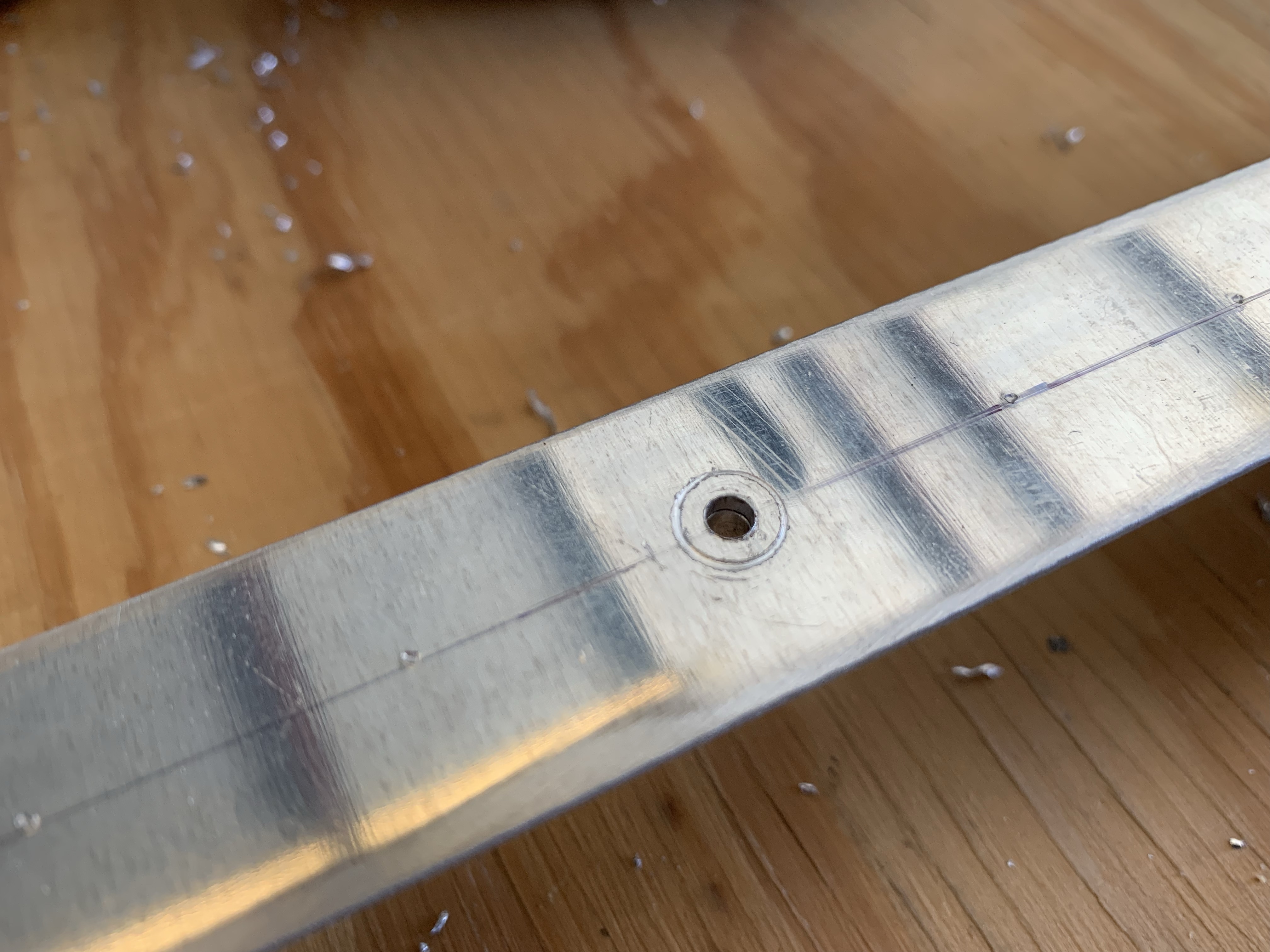
This was bothersome to me, since this is going to be a very visible part of the airplane that also likely won’t be painted…so there are limited options for getting rid of this ugliness. Now, this hole will eventually be countersunk for a #6 screw, but the screw head is still smaller than the scratch, so that wouldn’t help. I came up with the idea of maybe upsizing to a #8 screw, and to test if that would actually cover the scratch, I intentionally marred a piece of scrap and then worked on countersinking it, and found that I could cover the scratch if I was liberal with the countersink, putting the screw head just below flush.

So with that in mind, I kept going, moving on to drilling the rivet holes in the assembly. Everything seemed to be going well until I separated the parts for deburring and eventual countersinking, and found that the other side of those rivet holes were…let’s say inconsistent. Apparently my attempts to hold the drill bit square to the rail cap failed pretty miserably, and I drilled the holes in various states of crookedness. Still, the visible part looked OK, so I thought maybe the slightly off holes might be OK…until I tried countersinking them, at which point it was obvious they were crooked enough to cause problems with the countersink cage.

At that point, I decided it was settled that these parts were officially junk. Fortunately, the replacement cost isn’t bad at all – under $20 for the parts from Van’s – but I’m sure the shipping will be a bit interesting since both pieces are about 4’ long. Oh well, that’s the way things go.

Before ordering, it seemed prudent to look at the other two rails, just in case I fouled those up too. At least then I could combine the shipping cost for the parts. These are the two rails that sit on either side of the canopy, and they’re made of some C-channel type extrusions. Interestingly, the back end of each channel is precut at an angle to match the bulkhead behind the rear seats, but the rails still need to be trimmed at the front end. Marking these was a little interesting since they’re not a nice square cross-section, but trimming them wasn’t a big deal.

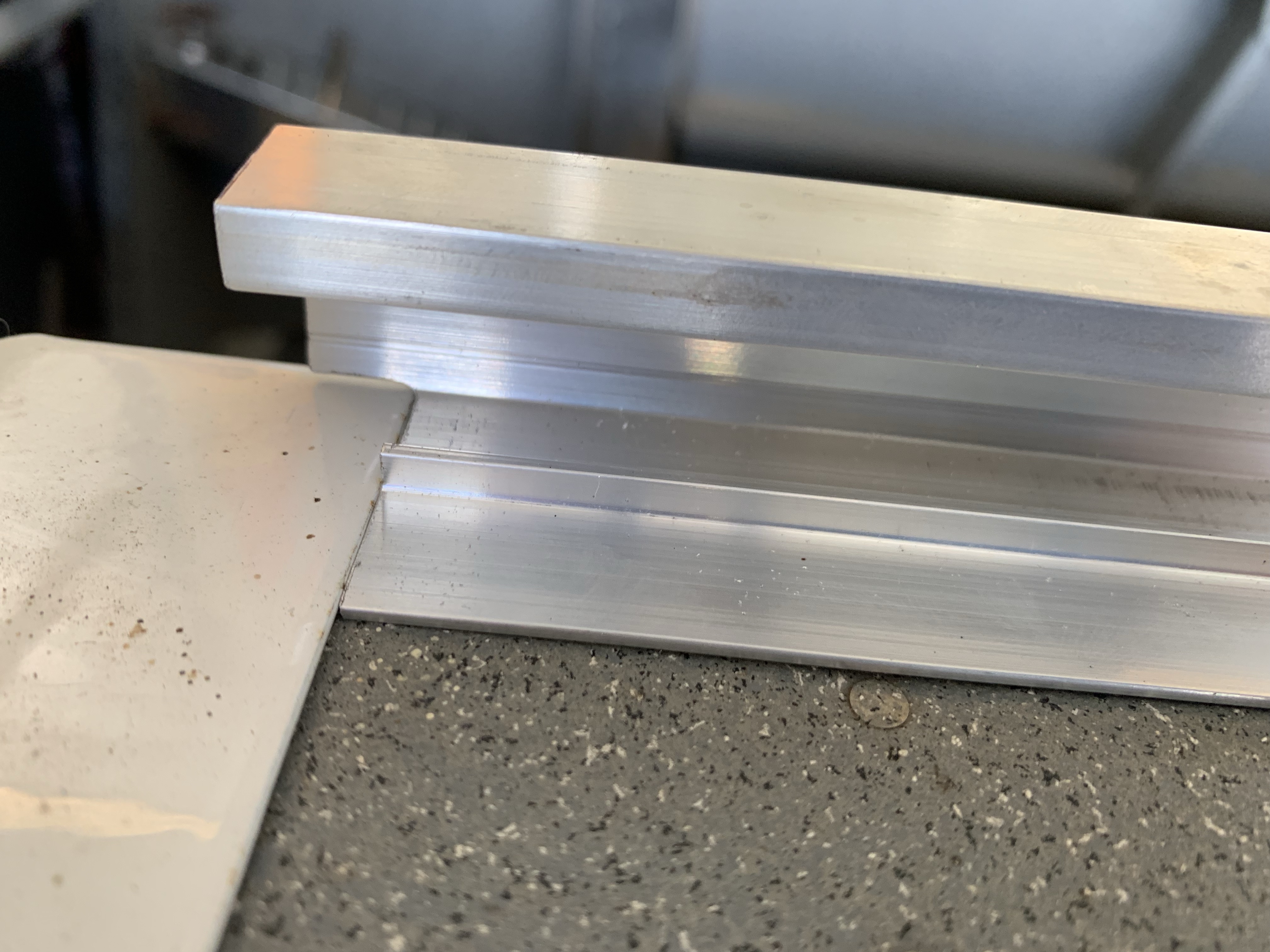
The more interesting part is that the forward end of the rails overlaps with the roll bar base, so the bottom forward corner of each rail needs to be relieved so it can sit flush elsewhere. This just required some careful rough cutting with the band saw and dremel cutting dock, followed by fine-tuning everything with files. In the end, I got a nice tight fit with the base:

Unfortunately, that’s all I can do with the canopy right now. Next steps would be to install the center rail on the fuselage and clamp these side rails into place, then start working on fitting the canopy frame, but…yup, no center rail for me. So I ended up crawling back inside the fuselage to reassemble some stuff I removed for riveting clearance. First up was reattaching the wire bundle in the aft most bay; I had to remove the the zip ties holding to the pad mounts to have clearance for bucking rivets. Was definitely a lot of fun getting my arms back in there; well actually, I could only get one arm in for aft pad. Turns out starting a zip tie one-handed is an interesting challenge.

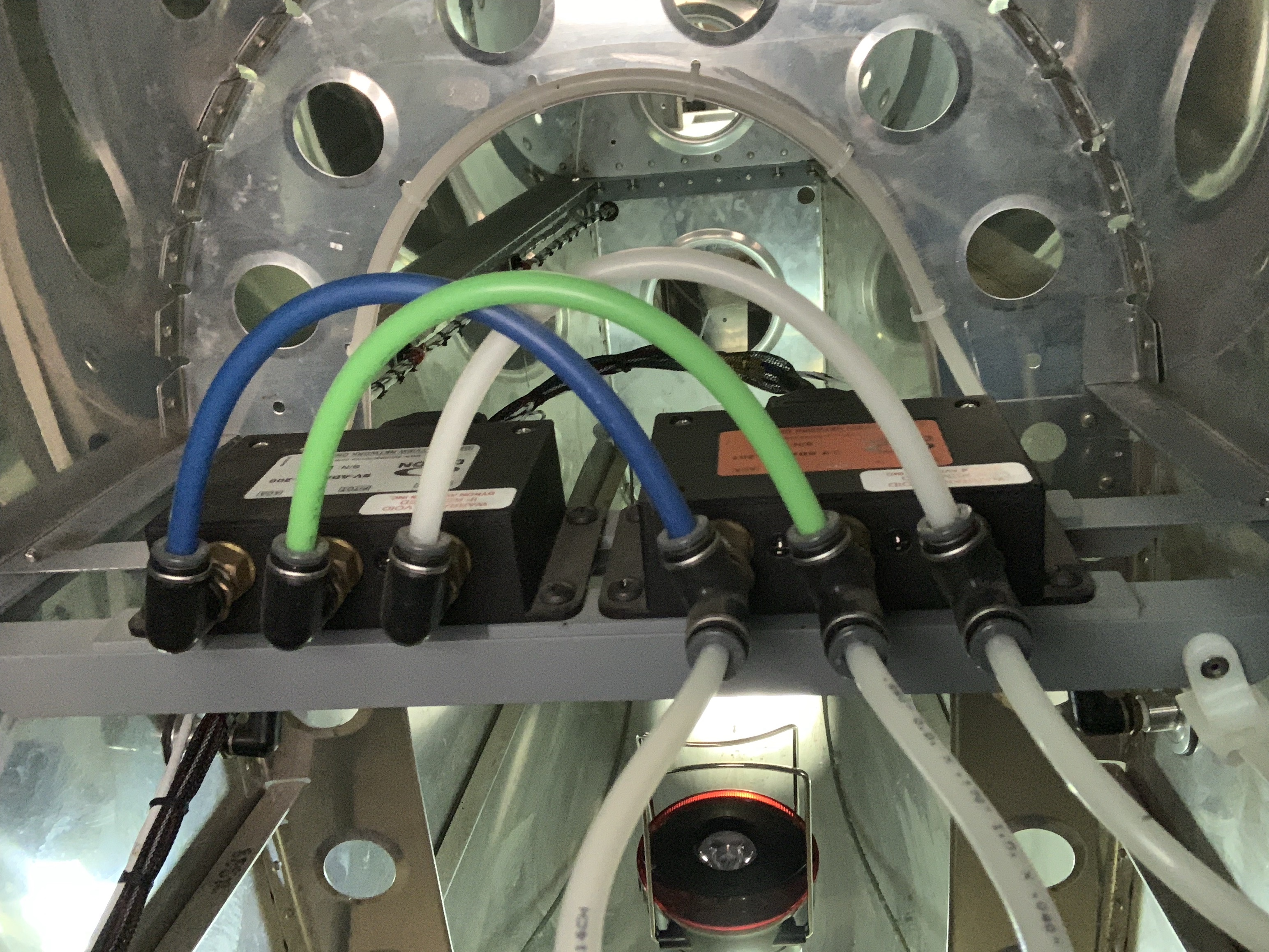
Next was permanently installing the ADAHRS mount. This is attached to the longerons with blind rivets, because there’s simply no way to get a rivet gun back in here. I guess screws would have been an option as well, but I don’t really intend for the entire mount to ever be removed, except in the case of a major systems overhaul way down the road. A side note here: the little “pop” you get when the stem breaks on a blind rivet is a whole lot louder when it happens inside an aluminum cone.

But hey, with the network/OAT connectors…reconnected…along with the static line, these are pretty mush ready to go. Only thing remaining will be routing the pitot and AOA lines back here at some point. Original plan here was to run them uninterrupted from the wingtip, though I’m kind of considering putting in disconnects inside the fuselage at the wing root, simply so I can go ahead and get the lines routed back here. I’m pretty on the fence about that.

Oh yeah, look, a photo:

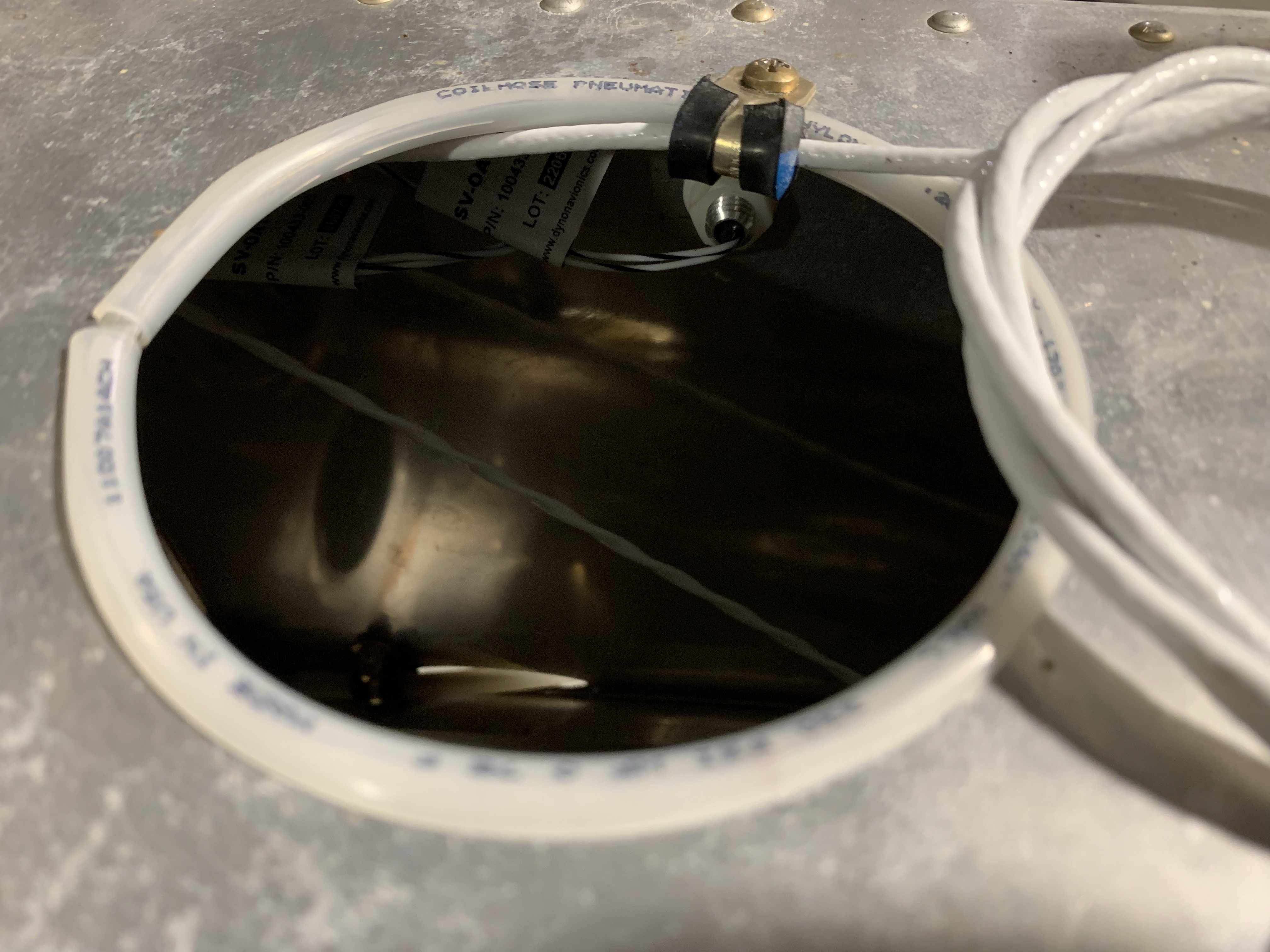
Finally, for one more random systems thing, I took care of some routing for the elevator trim cable. This will come up through the aft deck lightening/access hole; I went with the same anti-chafe setup I’ve done elsewhere, just taking some of my surplus static line, splitting it, and slipping it over the edge of the hole. Then I added an adel clamp to hold the wire in place where it passes through the hole:

Now I just have to figure out what to work on while I wait for parts. Kind of thinking I may go ahead and mount the empennage again, this time for what might be the last time – though I should be careful making pronouncements like that. With the empennage in place I could go ahead and finalize the wire routing and disconnects for the elevator trim servo. I could work on the tail light wiring as well, though that would require getting my hands dirty with the fiberglass rudder fairing.

The other complicating factor is that we’re two weeks out from heading out on a three-week road trip. I’d been hoping to make some good progress on the canopy before then, but it seems unlikely that’s going to happen – I imagine the last week pre-trip isn’t going to be super productive on the airplane. Hopefully I can at least get the replacement rail parts in, and get the center rail in place for future fitting. If I can get the canopy trimming done by the end of October or so, it should still be decently warm during the days, keeping potential cracking as a smaller concern.

Posted in Canopy, Electrical, Fuselage | Hours Logged: 3.5

Canopy rail do-over

A week after getting back from vacation and I’m still trying to get back int he swing of things. I did have my firewall forward kit come in while I was gone, and a neighbor was nice enough to grab the box and hold it until we got back in town. Yesterday I cracked open the box and admired the contents a bit. I probably ought to do an actual inventory but I wasn’t really feeling like counting rivets and stuff at the time.

I also got in my replacement parts for the canopy rail I bother – the day we left. So they’ve just been sitting around waiting for me. Today I got them out and started getting to it, though I didn’t actually achieve much. I marked off and made the relief at the forward end of the rail, then went inside to cool off a bit (it got up to near 90° today…yay Houston) before starting to bend the sheet strip that forms the rail cap.

In the meantime, it came to pass that we finally were ready to fly the Helio Courier I’ve been working with for the past few months, so I ended up going over and acting as copilot for that whole evolution. So no more rail work, but I got to fly in a cool old plane at sunset, which seems kinda like a worthwhile tradeoff.

Posted in Canopy | Hours Logged: 1

Finished fabbing canopy rail

Picked right back up on the rail this evening. I got to redo all the fun layout work I did the first time around – ok, it really wasn’t all that bad, but it’s still something like 50 holes to mark, punch, and drill on centerline, while keeping stuff aligned. Drilling the holes with the drill press was definitely slower than doing that same work by hand, but the results were much better. After getting all the deburring and countersinking done, I finished by riveting the cap and rail to make the finished product.

Next I get to mark a centerline on the fuselage and get the mounting holes drilled so this can be screwed in. Then I guess I get to start having fun with the canopy frame itself. For now, I just laid the rail on the fuselage for a photo op, with the slider block in place for good measure:

Posted in Canopy | Hours Logged: 2.5

Initial canopy frame fit

So…if I were to go by the construction manual verbatim, the next thing I’d be doing would be to locate the center slide rail on the fuselage, drill the mount holes, and bolt it in place. However, I’m hesitant to do that until I get a good sense for how the entire system works together. Of particular note here is how the center slide rail bends down at the forward end, which causes the back end of the frame to drop in place when closed and put an anchor pin into a locating block. This provides a much more precise location of the frame as compared to the somewhat loose-fitting slide block. What this all means is that, to my way of thinking, it might be necessary to work on the fore-aft location of the slide rail, to ensure that everything nests in place properly when the canopy closes.

With that in mind, today I started out by extracting the canopy frame from the finish kit crate in order to do some test fitting. That, in turn, required a bit of excavation, since the frame is at the bottom of the crate. Next, I gathered up the slide hardware, which took some time because I couldn’t find the bag with some specific screws for a while. The aft hardware is pretty simple – there’s the hard plastic slide block, which gets attached to the frame with a clevis pin. The only mild complication is that the block isn’t predrilled for the clevis pin, so that’s yet another variable in the fitment back here that I’ll need to work out. At the forward end, there are rollers that nest inside the slide channels, which then attach to mount points with screws, nuts, bushings, and spacers. Those mount pieces then nest into tubing on the frame itself, and will eventually be bolted in place there.

With all that stuff assembled, I got the canopy frame in place and slide closed. For now the slide channels are just resting in place on the cockpit rails; refining their position will be part of the larger fitting job. Similarly, the center rail is just sitting on top of the fuselage.

So far, this operation has posed more questions than it’s answered. For one thing, with all this stuff in place, I don’t feel like the canopy frame is able to go far enough forward. I don’t think it’s supposed to actually contact the windscreens support, but it currently sits about 3/4” apart when closed. Later on in the construction manual, when discussing laying out the cut to separate the provided canopy bubble into the windscreen and sliding canopy sections, it suggests trapping a sheet of cardboard between these two pieces to provide a straight cut line. That implies to me that these pieces should sit a lot closer together…but the only way to make that happen would be to modify either the anchor pin on the frame or the anchor block it fits into.

The other question concerns drilling that hole in the slide block. I haven’t been able to find any sort of guidance on where or how to locate that hole. This seems important too, since if it locates the frame too far from the rail, the anchor pin won’t be able to engage in the block. And of course for this whole operation, the actual position of the slide rail figures in.

So I called it a night on that somewhat unsatisfying note. At the moment, based on some fiddling, I think  I want to be able to move the slide rail aft a bit from where it’s naturally resting right now. This should be achievable with some more filing on the relief on the forward end, but I’m definitely going to be thinking things over before I do anything of the sort.

Posted in Canopy | Hours Logged: 1

More canopy frame head scratching

So the title sort of sums up tonight’s short work session, though I feel like I’ve got an idea of how to move forward with the fitting. I’m still going to let that idea marinate a bit before I try doing anything about it (plus I’m gonna run it by the Van’s forum people). Even better, tomorrow I’m flying a Young Eagles event and I see that one of the other pilots is bringing the RV-8 he built. Hopefully he shows up so I can pin him in a corner and pepper him with questions. You know, in a friendly sort of way…

Anyway, out of the assorted issues I outlined before, I felt like the first one to really consider was the large gap between the canopy and windscreen frames. As mentioned before (I think), the limiting factor on forward movement of the frame is an anchor pin at the aft end, which fits into a plastic block that rests against the back of the bulkhead just behind the back seat. One thought I had was to remove some material from that block to allow the frame to go further forward, but it seemed like I’d need to remove a ton of material. To help visualize how things might need to change, I decided to get the anchor block out of the picture entirely and see what kind of gap I could get with the anchor pin actually contacting the bulkhead – that is, as far forward as it could physically go if I went completely bananas on shaving down the block.

This seemed promising at first – looking at the gap on the left side (from where I was working), it was almost nonexistent. Using drill bits as crude feels gauges, the gap was about 1/16”, probably tighter than I’d want in real life. But then I noticed the gap on the right side was a good bit larger. I double-checked at the aft end to see if the anchor pin was centered, and it was. Hmm, seems like this frame is a little crooked. I was eventually able to get an equal gap up front, but only by shifting the aft anchor point as far right as it could go in the socket:

So it seems clear that I’ll need to bend the frame a bit to get both an even gap up front and a centered slide out back. That’s not too awfully surprising, it’s known that these frames almost always need some tweaking to get a final fit, though I wasn’t expecting a sort of twist like this.

But back to that gap up front – with the anchor pin touching the bulkhead and shifted as seen above, the gap was a nice consistent 3/16” all around, which seems like a reasonable number…until you remember that this is without the anchor block in place. At this point I started to get a twinge in the back of my mind, as usually happens when I’m getting subconsciously close to some sort of epiphany. The epiphany completed when I took another look at the anchor block and noticed that the hole for the pin went all the way through it – this wasn’t obvious until I removed the part sticker on the front side. All this time I’d been assuming that the intent was for the pin to barely engage the block, but now I think that’s not the case.

The pin itself looks to just be some rod stock that’s tapered to a point:

When engaging it with the block as provided, it slides into the block essentially until it gets to the end of the tapered area and stops:

Notably, at this point the engagement isn’t very positive. I didn’t think much about that before, but I was assuming the whole time that the hole in the block was similarly tapered to match the end of the pin. But it turns out that the pin can be inserted further, though it’s a pretty tight fit. It can, in fact, be inserted until it’s nearly sticking out of the front end of the block:

So that all homes in on a path forward to handle the gap issue: if the pin is able to freely drop that far into the block, the whole frame goes further forward and I no longer have the massive gap up front. And instead of shaving material off that block while trying to keep it square, I’d just need to open up that hole in the block a bit. Currently it’s a nice slip fit with a 1/4” drill bit, so I imagine the anchor pin is also 1/4” OD rod, and would slip in there nicely if not for the additional thickness of the powder coating. Probably I can just get in there with the next size up of numeric drill bit and remove a tiny bit of material, maybe still leaving the origin ID towards the front end to keep the tip of the pin from contacting the bulkhead and doing damage over time.

This, again, is an idea I’m going to run by the forums, and maybe by that -8 builder if I see him tomorrow morning.

As a final note, there’s going to be more frame bending to do in addition to trying to square the thing up. While looking over the manual section that talks about “massaging” the frame, it also mentioned “possibly” needing to bend the aft most portion of the frame for proper clearance from the slide rail. A glance at the plans says the appropriate gap is 3/4 – 5/8”. Yeah, I’m going to need to do some bending there, as my gap is currently way larger than that:

And that’s without even getting to possibly needing to expand the lower forward part of the frame for proper alignment with the fuselage sides. The alignment there doesn’t look too bad offhand, but I’m going to want to add some aluminum strips as per the manual to really properly evaluate things. Bottom line, I see a lot of trial-and-error application of force in my future.

Posted in Canopy | Hours Logged: 1

Canopy frame straightening

Let me start by summing up this evening’s work: that was kind of frightening but ultimately successful.

I shared my thoughts from the last session on the forums and got some good information. Most notably, my suspicion about the anchor pin/block nesting was confirmed: the pin should be going all the way into the block, not just a little bit. That should settle my large gap issues up front…well, once I get the hole enlarged. The hole is currently 1/4”, and the next largest drill bit I have is 9/32. Checking the different drill bit diameters with my calipers, the larger one seemed like it’d be a looser fit on the pin than I liked. To verify this (well, to convince myself not to just drill the block with what I had), I drilled a 9/32” hole in a piece of hardwood I had lying around – which I figured was about the closest delrin analog I had – and test-fit it to the anchor pin. Sure enough, it had a bit of slop that I didn’t really like. On the one hand, it’s probably not super important that this be a really snug fit, but on the other hand, it’ll never be as snug as it is when I first fit things, so I’d rather go for a precise fit out of the gate. So I guess I’ll be hunting up some weird drill bit sizes. Since the pin already goes in, just really snugly, I probably only need to remove a really tiny amount of material.

Anyway, the other item of discussion was the frame misalignment. Here, no one said anything good or bad about my intent to bend the frame, which is pretty much tacit approval on the Internet. That is to say, people are really good about pointing out problems with ideas like this. So my main goal tonight (and what I actually did first, before the block stuff discussed above) was to do the bending.

I’d been thinking offhand about how to do this for a day or two, and had a pretty decent idea how to proceed. Basically, I needed to lock the forward part of the frame and then pull sideways on the back end. So I made my big table into a jig of sorts. A piece of scrap 2×8 screwed to one end of the table served as my clamp point for the forward end, with another piece of scrap used to actually clamp the frame. I drew reference marks to center the frame on the table, then drew a centerline back where the anchor pin was. I’d hoped to find that the pin was obviously off-center, which would make me feel a little better about the whole thing, but that wasn’t the case…it was pretty much dead-on, definitely not out by the ~1/2” I’d seen while fitting on the fuselage.

Here’s a look at the whole setup on the table. I’d originally intended to hand a plumb bob from the anchor pin, but I couldn’t find mine. I decided that a combination square would work just as well, so that’s what’s seen here. It’s also worth noting that, in the end, I added more clamps to restrain the front end, because it took a lot more force than I expected for this operation:

Back to the whole “not off centerline” thing: that really made me stop and think, just to make sure I wasn’t doing something horribly wrong. Eventually I reasoned that the practical fitment on the fuselage was more important than the centerline. I’d checked the thing on the fuselage multiple times, it definitely wasn’t right, and in the end it needed to fit the plane, not some marks on a table. So I drew a second line 1/2” from my centerline, to use as a reference, and got to work:

At first, I tried just doing the bending just by pulling in the frame. After all, the manual talks about correcting the bow with “carefully controlled muscle power,” and in any case starting small is a good plan. But it was clear before long that this wasn’t good enough – I got the pin to move a tiny bit, but nowhere near what was needed. OK, time to get some mechanical advantage involved, in the form of a ratchet strap. The fun part was figuring out how to rig this. I ended up finding a large eyebolt lying around, which I installed on the bottom shelf of the table, so I could take the strap over the edge and anchor it down there.

The other consideration was some way to keep tabs on how much I was moving the frame – it was highly unlikely I’d get this right on the first pull, so I needed some way to repeatably pull to where I’d stopped on a previous attempt, and then go a bit further. To handle this, I just laid a piece of thin scrap wood along the left side of the frame. As the frame was pulled sideways, it’d move the scrap wood, and that’d serve as a sort of max-deflection indicator.

Finally, it was time to start pulling. I put what seemed like a decent amount of force on the frame, then released…and the pin had barely moved. The deflection indicator came in handy here, since I could just increment my pulling by a couple teeth on the ratchet each time. All in all, it took probably five or six iterations to creep up on the deflection I needed.

The scary part was that I was putting a lot of force into the system in the end. At first this concerned me because I was sort of necessarily standing right in line with the strap – if it broke I’d probably get a nice welt, but if that eye bolt came loos somehow I’d probably be in a world of hurt. So I tried standing off to the side as much as I could, but then on the last pull I noticed how putting all that force on a single point was noticeably changing the curve of the right-side frame bow. Oh boy, if I ruin this thing it’s gonna be really expensive to get a replacement. After releasing that pull, I sighted down from the back of the frame…whew, seems to have sprung back OK.

Time to do the real check, with the frame back on the fuselage. Before removing it, I clamped blocks on the table to ensure I could put it back in the exact same place if I needed to bend more. Then it was time for another deep breath as I carried it over to the fuselage, slid the rollers back in, and closed everything up…

…and it fits beautifully. Not quite perfect – with the anchor pin centered, the right-side gap is still maybe 1/32” of an inch, but I’m very sure I can live with that.

That was enough fun for one night. I suppose next I’ll worry about the anchor block, then refine the center slide rail, and then see what other bending I need to do while I still have this jig setup in place. I know I need to bend the aft end of the frame down a decent amount, and I may want to spread the forward bow a bit to match the fuselage sides.


whew


Posted in Canopy | Hours Logged: 2

More canopy fitting

So, the saga of the canopy fit continues. Yesterday I got in the special drill bits I’d ordered to open up the anchor block hole a bit. Good thing I ordered a couple sizes, because the amount the hole needed to be opened was more than I anticipated. But after a couple runs, the pin now fits in snugly, so all’s well with the anchor block.

Next up was continuing to consider the fitment interaction between the frame, anchor block, rail, and slide block. Taking care of the anchor block removed one variable from this scenario, but that still leaves two: the position of the hole in the slide block, and the position of the slide rail itself. Initially I was focusing on the rail itself. This piece basically has two “points” of contact with the fuselage, which in turn control its location. The first “point” is where the straight portion of the rail rests on top of the turtledeck. The second is where the bevel at the forward end contacts down inside the recess where the canopy drops in.

The goal I was going for here was to get the right gap between the canopy frame bracket and the slide rail – after all, in practice the slide block is what connects these two piece together, and it has to fit in that gap. To start with the gap definitely seemed too small, and the most obvious way to tweak this is to remove more material from the beveled area of the slide rail; doing this allows the rail to move further aft and increase the gap. So I filed some more material off the rail and fit it again, but couldn’t tell very well just how much the gap had changed. The reality is that it’s pretty hard to find an effective way to measure the gap in here.

So I decided instead to try something practical – I put the slide block on the rail, and figured I’d see if I could slide it in place between the rail and the frame. And while the gap looked on the small side, the block actually slid in place OK, though the fit was pretty snug. At this point, I decided to continue with this practical idea – if I could go ahead and drill the slide block, I’d remove another variable and be able to work just with the slide rail, and maybe even get everything finalized.

What I decided to do was to lay out the hold in the block such that the canopy frame sat as low as possible, so I measured the clearance between the pin hole in the frame and the edge of the bracket, and used that to work out the vertical positioning of the hole. For the horizontal positioning, I just put it on the centerline front-to-back. Then I went to the drill press and made the holes, before heading over to the fuselage to try a fit.

Unfortunately, I couldn’t get the pin to go through – the resulting hole in the block was a bit too low. There were a couple factors here – first, I probably should have given myself a little more margin for error when laying out the holes. But more importantly, when drilling the block, I should have put a wood block in the open center to help support things. With no support, the slide block wanted to deform a bit when I drilled, and I think that contributed to the holes wandering a bit too.

I didn’t quit at this point, though…I decided to see if I could work out a way to make this thing fit. It was probably already junked anyway, so I didn’t have a lot to lose. First idea was to open the hole in the block up slightly to #10 instead of #12…maybe that would give me just enough extra wiggle room to get the pin through. I reasoned that some slop here wasn’t a problem since this interface only locates the canopy frame when it’s open. Lo and behold, the slightly larger hole allowed me to get the pin through…but it took a good bit of encouragement. It was just occurring to me that this was still way too snug to work in the real world when I spotted another problem – with the hole in the block so low, the tip of the anchor pin was dragging on the slide rail. That took care of any brief thought I might have had to open the hole up even more – I’m not going to want that pin marking up the slide rail for the plane’s entire life. 

So it’s time for another parts order from Van’s, I suppose. As per usual, the part itself is pretty cheap, it’s just the shipping cost and the waiting that’s mildly annoying. Then again, I’ve got other stuff to work on around the house this weekend so maybe it’s not that much of a loss.

Posted in Canopy | Hours Logged: 2

Canopy slide block do-over

This past weekend I found a nice goody in the mailbox – a package from Van’t containing my replacement slide blocks. Yes, that’s “blocks” plural, because I ordered two of them, just in case I messed up a second time. Things have been busy since then but I got some time tonight to give this a second try.

Looking at the first block, I laid the holes out in what was a pretty good spot, but the actual holes ended up a bit lower. So for this attempt, I mostly focused in being more precise with the drilling, but also shifted the hole location up just a hair. As before, I used the center punch to spot the hole locations, but this time, instead of going straight to the drill press, I started the holes with a #40 drill bit I spun with my fingers. This way I could ensure things were starting off lined up. I also put together a spacer of scrap wood to put between the “ears” of the block to prevent the plastic from flexing while I was drilling; this was probably a big part of why the last block got mis-drilled.

From there, I opened the holes up gradually on the drill press; first a #40 bit using the holes I’d already started, then up to #30, and finally #12. That yielded a very snug fit with the pin, so I finished things off by running a #10 bit through both holes just using a hand drill; this gave be a better slip fit for the pin and also ensured both holes were collinear.

The first test fit on the canopy worked great; the anchor pin now sits just a bit above the center rail, and when the frame is slid all the way forward, the pin engages in the anchor block with the slide block fitting nicely between the frame and slide rail. With all that validated, there were some finishing touches to put on the block (or, as I thought about it, a few remaining opportunities to ruin the part).

First, one side of the block needs to be counterbore a bit to allow the clevis pin to sit flush. According to the plans this is required for the assembly to fit in the socket on the fuselage, though from my previous test-fit it worked just fine. But I’m not one to ignore instructions, so I used a 5/16” bit to make a nice little recess, so now the pin sits nice and flush.

The second thing that’s needed is a smaller hole from front to back on the block; this allows a cotter pin to be inserted through the end of the clevis pin and hold it in place. I was a little nervous about this since it required both precisely measuring the distance rom the block edge to the hole in the clevis pin, and also ensuring the hole was vertically aligned with the clevis pin hole. As before, I marked the spot and then started the hole by hand, before drilling all the way through with a #40 bit.

I think this is all that’s needed; there’s no real guidance given here other than “make a hole for the cotter pin.” I think the only thing that bothers me a bit is that the provided cotter pin doesn’t go all the way through the block, so it’s not really secured to my way of thinking. I’m somewhat inclined to look for some longer pins to use here, so they go all the way through the block and the ends can be bent out. Something else to think about…

For now, though, it’s done. Here’s a look at the clevis pin sitting flush, also showing the cotter pin head on the other side. I inserted the pin this way because with the canopy closed, gravity will be helping hold it in, for whatever that’s worth:

Here’s a better view of the cotter pin from the other side. Initially I’d thought of making the hole large enough for the head of the pin – or at least counterboring it like the clevis pin hole – but on second thought that’d make the pin really, really difficult to remove. Keeping the head exposed seems like a better choice to me:

Finally, we can see everything mating together nicely with the frame all the way forward:

Between the slide rail and the anchor block, the rear of the frame is rock solid in this position, though it can still move side to side since the rail isn’t yet secured. But having this done means I’m finally feeling confident about centering up the slide rail and getting it drilled and screwed into the fuselage – and once that’s done, the two forward rails can follow, and then I should be ready to move on to the canopy bubble itself.

Posted in Canopy | Hours Logged: 1.5

Attaching the center slide rail

OK, it’s time to get back to airplane working again, after a week or so of Other Stuff® going on. Today I decided it was time to grit my teeth, make some holes, and get this center slide rail installed.

Doing this meant first removing the canopy frame and the rail so I could mark a centerline on the turtledeck, which I did by stretching a piece of string between the forward- and aftmost bulkheads. With a few Sharpie marks made, the canopy rail went back in place, as did the frame. The latter was to ensure that I kept the spacing I wanted up in the receptacle area, with the slide block, anchor block, and so forth.

I already had the pilot holes in the rail from before, so I used those to initially drill #30 through the skin, which was easy except for the hole in the forward end of the rail. This sits down inside the receptacle area, and there’s absolutely no space to get a drill in there. That’s probably why the instructions said to drill this hole from the inside, but I couldn’t figure how I’d position it accurately doing that, which is why I drilled the pilot hole.

Getting this hole drilled was fun; I resorted to putting a short threaded bit for the angle drill into the pilot hole, and spinning it by hand – a lot – until I had a decent little pit created in the receptacle floor. With the rail removed, I then (just barely) had enough room to get in there with the angle drill and make the hole.

This brought me to getting the holes to final size for the #6 attach screws. I discovered while doing this that, for some reason, I have a #28 drill bit for this (which is a good snug fit for a #6), but my countersink bit has a #27 pilot. Which means I had absolutely no way of drilling the screw hole and then countersinking it. To solve this problem, I countersunk the holes while they were still #30, using that bit, and only then opened them up to final size. Sorta roundabout, but it got the job done.

Finally it was time to go crawl back in the tail again. With Josie holding the screws from outside, I installed the nuts and washers from inside, and also opened that forward most hole to #28 from inside – which apparently was an operation that needed to be photographed:

After that, I got the frame installed once again, and tested canopy movement. Strangely, the slide block seems to bind up just a little bit – not enough to prevent movement, but it seems to drag a bit. Something to look at later on, I guess.

I’d intended to clamp the side rails in place, but discovered that I’m not entirely sure how to do that. Probably not a difficult problem, but it made a good excuse to call it a night. In the meantime, here’s a look at the installed rail:

Posted in Canopy | Hours Logged: 2

Fitting the side rails and tweaking the canopy frame

So the goal for today was to get to the point of finalizing the placement of the side rails. Getting this done required doing some work with the frame itself to get the fit correct. The main goal was to get the sides of the frame to line up properly with the fuselage sides; this will ensure that the canopy skirt pieces fit nicely down the road when that time comes. The fit here is checked by cutting some thin strips of scrap aluminum, curling them a bit to match the curvature of the frame, and clamping them in place so their fit against the fuselage can be evaluated. With this done, we get a setup like this:

The previous photo was actually taken after frame tweaking, which is why the strips are fitting nicely against the fuselage. At first, though, the frame was a bit too wide, and the strips didn’t quite make contact with the fuselage, which meant I needed to squeeze things together a bit. The force for this was provided by a ratchet strap across the hoop at the front of the frame, but the other thing I needed was some way to reliably visualize how much I was bending the frame. This has more to do with the bending operation than the final dimensions of the frame, which can just be checked by re-checking the fit of the strips.

But for the bending portion, what I wanted to be able to do was to pull the frame to a certain point, relax and check the fit, and then pull it just a bit further on the next iteration. So I needed a good indicator for this purpose, and I went with a yardstick positioned across the top of the frame a little ways back, and clamped on only one side. To ensure precision, I put strips of masking tape on each frame and drew reference marks. The resulting setup:

After several iterations, I had the fit I wanted, with the strips just barely making light contact with the fuselage sides. At this point, I started making preparations for drilling the mount holes in the canopy rails. There are two prepunched holes towards the aft end of the rails, which get drilled from below, but the other four holes get laid out on the rail itself and drilled from above.

This was a spot where my level of trust in the plans was a bit on the low side. Not that I thought they were wrong, but more that it wasn’t quite clear where the reference point for measuring was, and it seemed a good idea to really understand where the rail mount holes would end up on the fuselage. The longitudinal measurements are made from the front of the rail – but my question was, did this refer to the very front of the rail, or the relief cutout I made to fit around the roll bar base?

The first hole was to be set 2 1/16” back; measuring from the back of the roll bar base put this hole just behind the joint between the aft spar carry through bulkhead and the canopy rail mount on the fuselage, which seemed like the right idea. But continuing to measure backwards, the third and fourth holes clearly needed to be positioned around the seat back support bracket – and starting with the roll bar base put the third hole obviously in conflict with that bracket, while the fourth one had lots of extra room.

This indicated to me that I should be measuring from the front of the rail instead; doing this moved all the holes forward by about 3/8”. Measuring this way, the third and fourth holes ended up nicely positioned around the seat back bracket, but now the first hole seemed to interfere with the carry through bulkhead joint. This seems wrong and baffled me for a good amount of time, but after evaluating the layout a bit more, I realized that the lateral position of the hole put it almost exactly between two of the attach rivets – which are spaced kinda far apart. OK, this was starting to seem a bit more reasonable.

Still, I was unsure, so before committing to anything, I went in and did some research – which yielded absolutely nothing. That is, no one saying “oh yeah this is how it works” but also not “oh no no no don’t do that.” That was enough for me to decide that the intent of the drawing was for this screw hole to go through the bulkhead flange.

So I drew the hole layouts on the bottom of the rails, intending to drill those pilot holes on the bench and then use them as a template later on. But before that, I laid each rail in place to recheck that the hole positions appeared rational. The only tweak I made from this fit-up was to adjust that first hole forward a bit, in order to have it land directly in line with the rivets in the bulkhead. To do this, I just laid a ruler along the rivet centerlines and under the rail, and drew a new mark to adjust my hole layout (the mark hasn’t yet been drawn here):

And so I finally got my mount pilot holes drilled in the rails…but then while reviewing he construction manual, I realized I wasn’t done tweaking the frame itself. The one adjustment left to be made was to get the proper vertical distance between the aft tip of the frame and the center slide rail. I figured this was unlikely to tweak the width of the forward end of the frame, but better safe than sorry.

The called-for spacing here is 5/8-3/4”, and I was well in excess of that. With a piece of 3/4” MDF on the rail, there’s still a good inch and a half of extra space:

To do the actual bending, I screwed a piece of scrap lumber into the tabletop, using a couple of 3/4” spacers to create a nice gap in the middle, with the entire apparatus spaced a few inches shorter than the length of the back end of the frame. This allowed me to tuck the aft end under the lumber and simply push down on the forward end of the frame to get my bending done. I would have preferred something more controlled, like I did with spreading the forward end, but I couldn’t figure a way to really do this with controlled force. Instead I just sort of estimated where the frame was sitting relative to my body while bending.

Here’s a look at the bending “jig:”

Also, rather than doing a lot of installing/removing the canopy to check the fit, I instead did measuring off the table for the rough bending. I already knew how much I needed the aft end to come down, so I set the frame on the table, measured the vertical distance from the table, and figured the new height I was going for. After a couple bending iterations, I was getting close and so I verified the fit on the fuselage before doing the final tweaking. It all ended up working quite well and now I’ve got a much nicer gap from the center rail:

After a final double-check of the fit – as I’d figured, the front of the frame still fir just fine – it was finally time to clamp the rails in place and do some drilling. This is kind of fun because it’s a little hard to work out a clamping strategy. Notably, the manual says you can also tape the rails in place, but that just seems nowhere near accurate enough. I ended up with a C-clamp at the back of each rail, and another about 6” back from the front end.

To position the rails for clamping, I started with the frame nearly full-open – just far enough forward that I could still get the clamps installed (once in, m the clamps would block movement of the frame). I got the rails set an equal distance in from each side of the fuselage, and with the rollers roughly centered, and clamped the back ends. Then the frame went forward and I repeated this exercise up there.

As a final sanity check, I measured the distance across the rails at a couple different spots. This showed that the front ends were about 1/8” further apart than the backs, so I did a little more adjustment of the spacing. I really would have preferred to be able to run the canopy through the full range of motion with everything clamped in place, but that simply wasn’t possible. In the end I just had to measure multiple times and then just kind of go for it.

Drilling started by taking the existing #40 holes (the four I drilled in each rail, plus the two prepunched holes in the fuselage) and using them to drill into the mating piece. The holes laid out in each rail were easy; the other prepunched ones were a little more fun. Those required laying inside the fuselage in various uncomfortable positions while wielding an angle drill (for the forward pair) and a cordless with a 12” bit (for the rear pair, which sit really close to the bulkhead behind the rear seat).

It was only after drilling all these initial holes, adding clecos as I went, that I finally got to test the full motion of the frame. Whew…no binding. That was a bit nerve-wracking.

Next, I needed to create access holes for the rearmost hole in each rail. All the other screws sit outboard on the flange of the rail, and are easily accessible from above, but the rearmost is inside the rail, so a larger hole has to be drilled in the top of the rail so a screwdriver can pass through for installation. This hole also had the benefit of allowing me to do all the rest of the drilling from above.

With the access hole done, the rails got clecoed back in place and I enlarged each hole first to #30, then to the final size of #21. Then I got to pull it all apart and deburr the holes I’d just made. Remember those forward most holes whose placement I worried about so much? While they didn’t quite land exactly between the two rivets, they’re pretty close, and are nicely in line with the row itself:

This was about the point where I was ready to call it a night. One thing I’d noticed earlier was that all the fitting had scraped up the powder coat on the roll bar base, so I wanted to touch those areas up before installing the side rails for good. So I hit those with the touch-up paint, and then as a last act took a look at those aft most screw holes in the rails. As mentioned before, the screw placement here is further inboard, inside the channel itself. A consequence of this is that the screw head actually interferes with a raised part of the channel, and I’ll have to relieve that a bit so the screw can actually sit flush.

The interference, along with my marks for making the relief, can be seen here:

So that’ll be a good spot to pick up tomorrow (which I happen to have off). I’ll actually need to do one more trial fit, because I forgot one thing: the outboard part of the aft end of the rail actually sticks out past the fuselage sides, and will need to be trimmed. I should have marked that before removing the rails tonight, but I forgot. That’s OK, there were much worse mistakes I could have made.

Once the rails go on for good, there won’t be much left but to start messing with the actual canopy bubble…

Posted in Canopy | Hours Logged: 5