Panel

Panel-ey stuff

OK, so I’m not logging any actual time for this, which is pretty much in keeping with what I’ve been doing all along. I only really log time spent actually out in the shop. Time spent doing random research/reading/design/admin stuff I don’t keep track of (if I did I’d probably be over 2000 hours by now).

Anyway, after continuing to tweak and move stuff around in the panel design, I decided it was time to update the mockups in the plane. I decided I didn’t like the intercom in the right console after all, and put it back up on the panel. So now all my physical switches are either on the right console or at the lower left of the panel.

Basically, the left-side switches are all what I’m considering “immediate action” items – things I’d need to hit immediately in case of an emergency. Fuel pump and starter arm switches would come into play in case of a loss of engine power, autopilot servos might need to be disabled in a hurry if they went bananas for whatever reason.

Right-side switches are all less-urgent things. I might need to move these in response to an issue, but not necessarily urgently. It’s not depicted here, but what I intend to do here are sprinkle in some guards in strategic spots to help group the switches and allow for finding them by feel if necessary.

I didn’t really do any chair-flying with the new setup tonight, just climbed in long enough to get the photo and make a few token airplane noises. From here I think I’ll do some serious chair time, working through checklists and such to see how everything flows. The one concern I have at the moment is that the rearmost switches on the console seem like they might be awkward to reach. I don’t think I can put the switches much closer together, so I may end up moving the ignition switched to the right wing to live beside the CPI2 controller they’re associated with.

Always something more to think about…

Posted in Panel

Finished the riveting and other bottom skin stuff; back to panel things

So today we were finally able to get out and get this riveting finished up. It was only 16 rivets in total but some of these are a little interesting due to the shape of the cooling ramp and the stuff around it, so there was a bit of careful work involved. With that done, all that was left was to seal the edges of the cooling ramp. Since this is the “exit” area of the cowling, there’s potential for nasty stuff to get inside this void area and cause unpleasantness. All the seams so far have gotten a layer of siliconized sealant, but that doesn’t work for this last bit. Here, an exposed bead of sealant is applied, which means this needs to be paintable, which in turn calls for my old friend – fuel tank sealant.

I bought a single-use cartridge of the stuff a while back just for this purpose, since even if I’d kept any sealant from my tanks, it’d surely be no good by now. The cartridge is nice because it includes an internal mixing setup, and fits in a caulk gun so laying down a bead is super easy. As for the bead itself, I wanted it to be nice and tidy (even though it’ll be 1) under the airplane and 2) painted over eventually), so I took the extra time to put down masking tape to match where my fillet tool would leave its edges.

Here’s one seam after applying the sealant and smoothing it into a nice fillet:

And after removing the tape:


Next up was getting back to panel stuff. While I did the major part of the cutting a while back, for the main panel, there were still the two panel wings that need attention. One thing I added on to my most recent Van’s order was a pair of nicer anodized aluminum fresh air vents. The kit came with a couple cheap plastic vents that are pretty well-known for not really closing tight at all (as well as just looking cheap). The aluminum ones are pricey but way nicer.

This is relevant because I’m putting the front-seat vent in the left-side panel wing, so obviously having the actual part I’m going to be using on hand is important. The fun part is figuring out whether or not this will actually work. The vent itself is circular, but it has a 3” square flange used to actually mount it. Given the limited area here, that makes this something to be considered very carefully. I’ve been idly looking at this for a week or so, so today was just the time to get serious.

In order to help with the fitment, I decide to start by making a template of the vent; essentially, this would represent the cutout I’d need in the panel itself. So it’s a 3” square piece of think aluminum (scrap from the previous panel cutout activities) with a large cutout for the vent body to protrude through. The idea is that I can use this first to verify there’s room for this in the desired spot, and then later on it can become my guide for drilling the screw holes and cutting the larger hole.

The template in question:

This is how the vent will mount in the panel – from behind – because I don’t want the whole big square bezel visible. The downside of this method is that the final circular cutout edge will be visible, unlike the other panel cutouts that are hidden by small bezels. But since the panel will be painted flat black, whatever irregularities I end up with (I’m sure there will be some small ones) shouldn’t be obvious without really close inspection.

And here’s a look at the template in place on the panel wing, showing the constraints I have to work with. On the outboard edge there will be these little tabs, part of what ties the panel wings into the fuselage skin. On the right side there’s the nutplates by which the panel center attaches. The sharpie line on the right is where the actual edge of the center will be, but since that overlap will be in front, and the vent bezel behind, those are OK to overlap as seen here.

The other concern is the switch row below the vent. The mockup seen here isn’t actually accurate; when I made these a while back, I underestimated the size of the switch holes, so the actual label text will take up more vertical space than seen here. I think it will still fit OK – there’s a fair amount of space below the mockup and the bottom edge of the panel – but I want to be sure, so before I commit to any holes here, I need to make up a more accurate mockup. The concern I have here is that the attach screws for the vent will interfere with the labels.

So that’s where we are today. Tomorrow once the sealant on that cooling ramp has cured, and I’m sure everything is in order, I figure I’ll start adding stuff back to the fuselage to prepare for wiring harness stuff – the baggage bulkhead, shelves, and so forth.

Posted in Fuselage, Panel | Hours Logged: 4

Panel air vent

Boy, I should really work on this thing more. I’ve kind of been procrastinating because I was a little concerned about cutting this air vent hole. I’m not entirely sure why though, it’s not a strange shape or anything…I guess it was just the careful placement needed. There was also the thought of how to make the cutout…I used my nice little circle hole cutter for my template, but since I wanted to locate the actual hole based on the screw holes, cutting the actual vent hole to final size and getting the center exactly right seemed rather challenging.

In the end, though, I realized I could still use my hole cutter, just set smaller to make the initial cut. Then I could gradually enlarge the hole to my cut line and get everything nice and precise. So I just had to get past that hesitation to make that first assault with the drill. Of course, as usual the actual act was anticlimactic. Getting the hole expanded was a bit tedious, but that’s just the breaks of working up to cuts like this. I roughed the hole with a cutting bit on the Dremel, then used a half round file to remove the tooling marks and even out the curve a bit, then finished it with a sanding drum and a flap wheel. I also used an older flap wheel worn to a bevel to round the forward edge of the cutout a bit, since this will be visible. I may end up dressing that edge up some more, we’ll see how I feel about it later this week.

But hey, now I’ve got a vent. No mount screws yet, though…I’ve been considering whether I want to get normal cad-plated screws (which would match the per-plans screws attaching the center panel to the wings) or look for some black hardware to blend in with the eventual black panel paint. That’s not something I need to solve right now, though.

Next up is the real fun, cutting the right wing for the SDS CPI2 controller. That thing has an octagonal shape, which should present quite a challenge. Oh, and the edges of the cutout will be exposed just like this vent, so I can’t just sort of get close and then let the bezel cover things up like with all the other avionics. Should be quite a journey…

Posted in Fuselage, Panel | Hours Logged: 1.5

CPI2 controller cutout

Continuing with the “making holes in stuff” theme, tonight I decided to bite the bullet and get going on this most fun cutout of all. First I ha to finalize the position of the controller – much like with the air vent on the other side, there’s not really much room here to be flexible with the positioning. It’s even more notable here since the switched at the bottom of the panel wing are the larger 3PDT units, so I’ve got to allow for a bit more vertical space.

Unlike the big panel cutouts, here I did the rough cutting with a Dremel cutoff wheel rather than the jigsaw…much easier to set up since no pilot holes are needed. Enlarged the hole to near the outline with a cutting bit, and then went to work with a file. The fun part here is figuring out how to creep up on the final size when I have eight sides to deal with. The long sides aren’t that bad but the beveled corners require real care to try and not mess up the corners.

Anyway, tonight I got as far as getting the long sides done, along with one corner, and that seemed like a good time to call it a night. I suspect that tomorrow I can get this finalized, though really I’m only at a rough-cut stage still. Once I open the cutout to the lines, I’ll still probably have some fine-tuning to get the controller to fit precisely. And then there’s the fun of spotting and drilling the four mount holes – since the screws thread directly into the controller, I can’t really easily use the unit to lay out the screw holes.

But hey, if I can get this done, the rest is just drilling some switch holes, which should be a cakewalk…as long as I don’t mess anything up, that is…

Posted in Avionics, Fuselage, Panel | Hours Logged: 1.5

Controller cutout completed

Back to work on this cutout tonight. There’s not really a ton to report on, I just spent a whole lot of time carefully and gradually removing more and more material on those corner tab areas, while continually trying to fit the controller through the hole. Pretty tedious work overall, but that tedium was rewarded with a nice tidy cutout.

Spotting the mount screw holes turned out to not be as bad as I thought. By disassembling the controller’s face from the mount box, I could use the holes through the face to start the screw holes. I was a bit peeved when I realized there weren’t mounting screws included with the CPI2 (at least not that I could find), but it turned out the Torx screws I ordered to use with some of the Dynon stuff worked perfectly for this spot as well.

This should all look really nice once the panel’s painted at some unknown future date:

So now I guess it’s time to lay out and drill the assorted switch mount holes on these wings, and then I’ll be able to start hanging this stuff in the fuselage again.

Posted in Avionics, Fuselage, Panel | Hours Logged: 2

Switch holes

Just worked on laying out and drilling the switch holes in the panel wings tonight. Pretty straightforward stuff, most of the thinking was around finalizing the actual locations; I knew where the switches sat relative to each other, but had to decide where to locate the entire bank relative to the surrounding area. I ended up centering the two ignition switches below the controller, since those items are associated, and then for the three switches on the left side, I just put them as far inboard as practical, figuring it would help with accessibility.

With those holes done and the switches installed, there wasn’t much to do except to put the whole assembled panel back into the fuselage:

Of course, after I took this photo, I realized I’d forgotten one thing: the left wing also needs a hole drilled for the panel/flood light dimmer. I got so excited about finishing up the other switches that I forgot that one, so I guess I need to pull this apart again maybe tomorrow and get that fixed up.

In other news, I got an email today from Van’s with the bill of lading for my finish kit – so I guess I’ll have that on hand in the near future. Now if Titan would just get my engine shipped…

Posted in Fuselage, Panel | Hours Logged: 1

Random-ish stuff

Picking up where I left off before, the first order of business today was to remove the panel stuff again so I could drill that forgotten hole for the panel light dimmer. Nothing too crazy there, just a single hole to drill, not complicated at all. There was another item to take care of as well…while looking at routing for the fresh air vent ducting, I realized I needed an adapter/plenum on the back side of the vent. I found that in the box with the original plastic vents…the catch was it wasn’t drilled. So while I had the panel off, I match-drilled that to the vent, and reinstalled it with the plenum. My thinking here is that I’ll want the ducting in place while I’m working out wire harness routing.

Once I had the panel back in the plane, I started adding other parts back in, starting with the baggage bulkhead. My intent was to go ahead and reinstall the avionics and fuse shelves, but first I was eyeballing the rivet holes for the baggage bulkhead…should I go ahead and rivet those, or would there be reason to remove that again down the road? More thinking…but in the meantime I did go ahead and cut the ducting to length and temporarily install it:

Eventually I decided to sit down with the construction manual; first to make sure I’d checked off all the completed steps for the fuselage riveting, and then just to review the entire fuselage section and flag spots where there sections to revisit. Much better than my previous method of “uhh I think there was something back somewhere.”

In the process of this, I read ahead and realized that I should go ahead and work through fitting the forward upper skin – get everything match drilled and prepared, essentially to the point that all I have to do is riveting once I’m done with the wiring. Basically, this comes down to making sure I get riveting and stuff done before I add in a bunch of components that could get in the way.

So at the end of the day, I ended up removing all the avionics from the panel and storing them away again. Definitely don’t want that stuff inside while I’m match drilling and such. It looks like most of this should go pretty quickly, so I’m not delaying the wiring stuff by a whole lot.

Posted in Fuselage, Panel | Hours Logged: 2

More panel prep

More of the tedious stuff tonight. Most of what I did was just cleaning up all the rough edges on the panel components, and in this case it was kind of a worst-of-both-world situation: the panel attach strip (which joins the panel wings to the skins) has a whole lot of nooks and crannies, but at least it’s made of thin material. Meanwhile, the actual panel components have mostly long straight-ish edges, but the material is super thick. So basically this was just a good solid hour of filing, followed by some final edge polishing on the bench grinder where possible.

After finishing that up, I went ahead and countersunk all the flush rivet holes on the panel components. With that done, I’m all set to do some more riveting here…but that’ll be another night.

Posted in Fuselage, Panel | Hours Logged: 1.5

Panel assembly, forward skin fitting

Tonight I got straight to work with the riveting on the panel parts. First up were the nutplates, by which the center panel section will attach to the subpanel “wings.” Then I got to rivet the attach strip onto the subpanels; in this case, only some of the rivets are set, specifically omitting some near where the subpanels connect on the aircraft centerline. If all of these rivets were set, the entire assembly would be made rigid, and it’d be impossible to get it in and out of the aircraft…and I’m not ready for permanent mounting yet. If nothing else, these things need to be painted…

Next up was installing some stuff preparatory to fitting the forward upper skin. In addition to mounting the panel assembly in the aircraft, I also brought the roll bar back over and temporarily bolted it into place. 

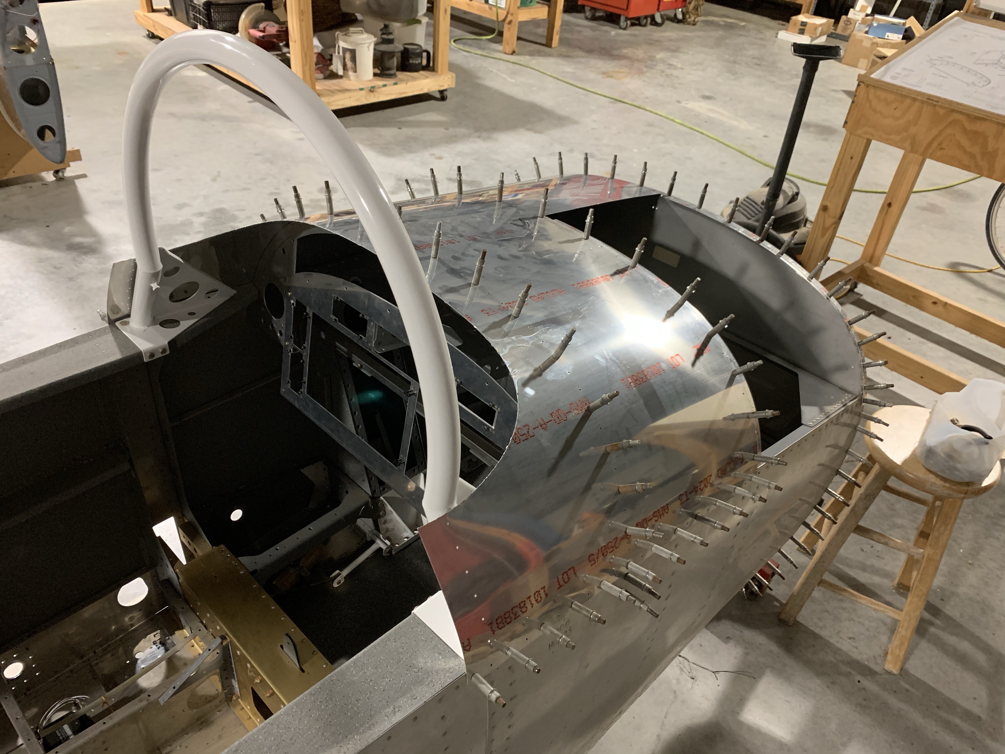
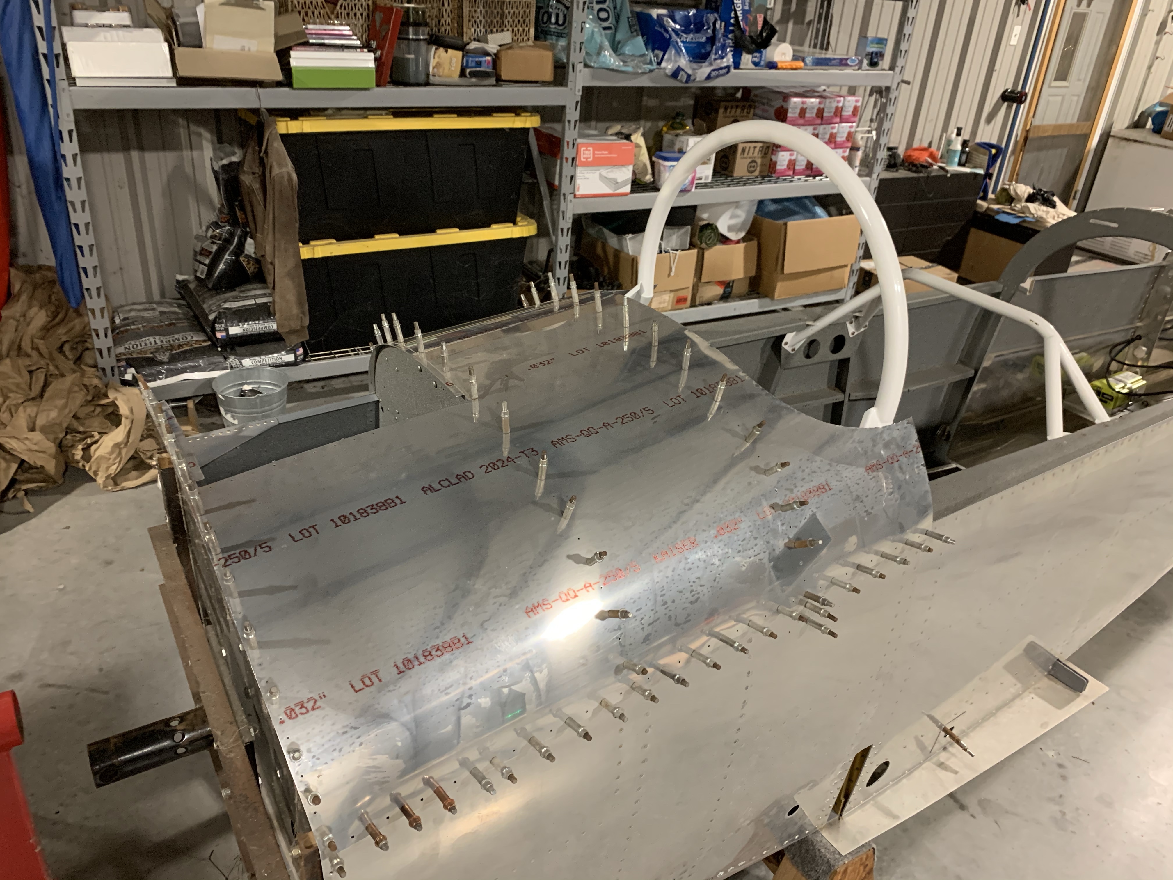
With all that in place, it was time to break out the skin itself for fitting. The manual specifically calls for removing the vinyl covering on the inside, presumably because this is a tight fit and that extra material wouldn’t be very helpful. I just want ahead and removed all the vinyl, in keeping with my general practice of just ripping the stuff of and not keeping it on like some people do. Then this skin needed some trimming – I’d removed one of the portions a while back, for reasons I don’t even recall – this was the cutout section where the skin wraps around the roll bar. Tonight I also needed to remove the section where the baggage area door will be.

With that done, and with the baggage door support strips prepped and clecoed onto the skin, it was time to attach the thing to the structure. This was a bit tedious due to the thickness of the skin and the curvature involved, but nothing too awful. Just got to be liberal with the clecos to make sure everything sits good and flush.

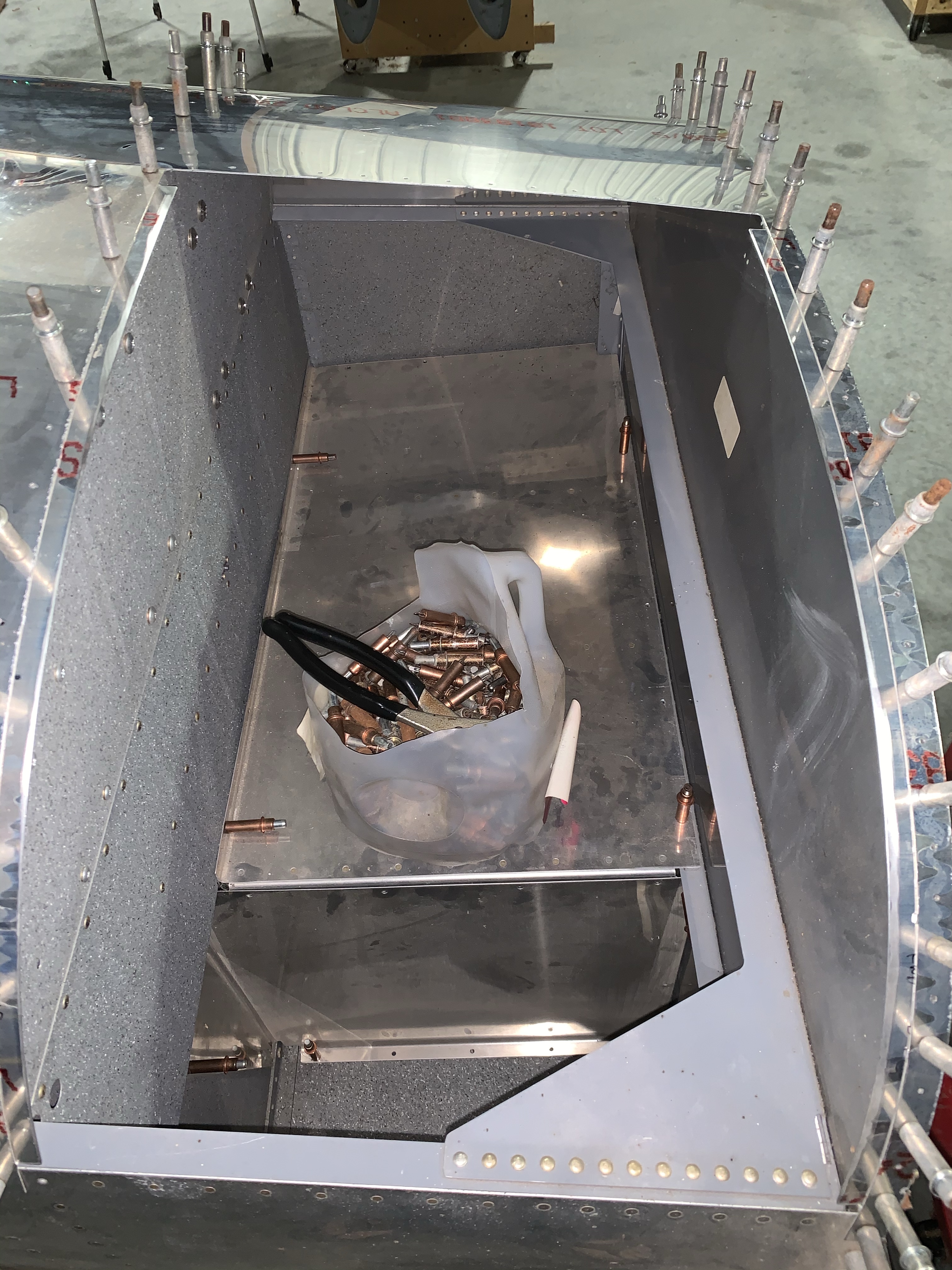
That got me to a good stopping point for the night, so it was just time to take some photos. It’s kind of impressive to see in person just how sizable the forward baggage compartment opening is:

It actually extends beyond the aircraft centerline:

And just for more illustrative purposes, I temporarily installed the baggage compartment floors and such to show the space available up here, with one of my milk jug cleco holders for scale. Not bad at all:

I guess next up I get to do a bunch of match drilling, though there are also a few more small parts to be installed first.. Reading ahead in the manual, I’d be removing this skin not too long after doing that work, but in this case I think I’m going to leave it a bit longer. The reason for this is that my finish kit will be here in a few days, and I’d like to at least briefly lay the canopy on top of the fuselage so I can get an idea of what area of this skin will be inside the canopy. That’s of interest to me since I intend to install both a GPS antenna and a couple of cooling/defrost fans on the glareshield, and I want to make sure I have a good idea of the space available.

Besides, it’ll just look cool, and that’s important too.

Posted in Fuselage, Panel | Hours Logged: 2.5

Deburring stuff

No photos tonight, nothing especially cool to speak of. Most of the time was spent finishing the edges of the forward upper skin – filing off the little nubs from where I removed the unused sections, smoothing everything out, cleaning up the edges. I also deburred a few other remaining things that I hadn’t picked up yet, namely the baggage hinge support and spacer.

The other thing I wanted to get a bit ahead of was figuring out where to mount the ELT remote switch. I started trying to sort of visually estimate the fit of the switch on one of the panel wings, but it was far from obvious whether or not it would fit. So I ended up using some scrap to make a little rectangular plate the size of the switch mount face, just so I could get a better idea of the fitment. That allowed me to see that yes, it’d fit over on the right panel wing just fine. Now I just have to actually make that hole…

Posted in Fuselage, Panel | Hours Logged: 1