Electrical

Harness assembly part 10 (mostly the intercom connection)

So I picked up today with the shield ground bus I mentioned yesterday. I already had my idea of making a bus out of some thick aluminum stock, but the one thing I couldn’t work out to my satisfaction was how to secure that bus. My preference was to secure it to the D-sub connector somehow, so that it wouldn’t potentially be another thing to disconnect when pulling the panel.

One thought I had was to glue it to the backshell, but that presented a couple issues: first, if I ever had to open up the backshell for maintenance, the bus would probably get in the way. Second, I’d have to make sure none of the screws attaching the ring terminals were long enough to go through the bar stock, while also making sure they had enough thread engagement to hold. Doesn’t seem like much fun. Finally, just before bed last night, I had an idea. What if I used two pieces of stock and two screws to clamp the bus on the connector, and used those same screws to attach the ring terminals? It seemed both doable and elegant.

So that was this morning’s fabrication job. It’s pretty straightforward; two pieces of 1/8” stock just a bit longer than the backshell is wide. Both pieces have two screw holes drilled in assembly so they line up. The real fun is that one piece has small holes that are drilled and tapped for the #6 screws, while the other one has larger holes for the screws to just pass through. So the attach procedure is to to thread the screws through the tapped pice to secure the terminals, and then the other piece slips over the long screws and clamps in place with nuts.

Here’s the first mock-up of the thing:

Alright then, time to finish up the terminations and get this connector put together. This one requires some attention, because it’s not by any means a case where I just put a pin on each wire and then install them in a connector. Nope, several grounds in the shielded bundles go to the shared shield ground, a couple of other mic grounds get tied together, and so on. And the end result is a really fat bundle that barely fits in the backshell strain-relief clamp.

Also, as if that wasn’t enough, about the time I finally got the thing buttoned up, I realized that I’d completely forgotten to add the audio input from the SDS CPI2. The good news there is that I heard back from them and my TS connector should work well. That still meant I had to open the whole thing back up and not only add another pin, but tie in yet another ground to the ground bus.

But the thing is finally done. Before assembling it again, I wrapped both parts of the bus with silicon tape. The idea is to help this grip the backshell better without putting a ton of clamping force on it, which probably wouldn’t be good for the connector.

The connector with the bus and ground leads installed:

And a view from the connector side. I want to get some shorter screws from Spruce here, so they don’t stick out quite so far, but for now this gets the job done:

The intercom connector means that I’m finished with the service-loop branch that goes to all the stuff in the center panel. Next up are terminations on the branch serving the upper avionics shelf. After the fun of the intercom, I took the easy one first here, the ARINC-429 interface box; this is the device that allows the TSO’d Garmin GPS to talk to the Dynon displays, so I can get guidance from the IFR navigator on the big screens. This connector is super simple, just six wires (strangely, in a 25-pin connector).

I considered moving on to the com radio connector, but for that I need to do more splicing of a couple leads together, and I didn’t feel like starting that tonight. That’s a job for tomorrow. And when that’s done, I get to go to the real fun, which will be the crammed-full EMS connector.

Posted in Avionics, Electrical | Hours Logged: 4

Harnesses: more connections, and starting installation

Yeah, I got tired of trying to keep track of what part of harness stuff I was on. Besides, some better variety in these post titles will make it easier if I ever need to go back and refer to anything here.

I picked up this morning with the com radio connector; not super complicated, but it did call for a few window splices (doubled power/ground inputs, plus a combined phone/mic/PTT ground). All in all, though, a pretty uncrowded connector. But that just left me with the granddaddy of them all: the EMS sensor connector.

Even the pile of heat shrink labels I printed for this thing looks impressive:

It was really fun trying to go through all 30 or so wires in this bundle and making really sure I was getting the labels right. The one nice thing is that these were almost entirely one wire-one pin; the only exceptions were the power and ground lines for the trim servo indicators. For the former, I window spliced them into the +5V out wire (which will go FWF for sensors up there), while the latter I was able to just twist the striped ends together and combine into a single pin, since the trim wires are pretty small.

Then it was time to pin everything up, again being really careful and triple-checking each pin before inserting it into the connector. Yeah, that’s a lot of stuff:

After that, I just did two more fairly simple connectors. One was the Skyview network cable that will connect the forward and aft network hubs; the other was the partial Skyview network cable for the autopilot roll servo. The autopilot servos use the same data pairs as the regular Skyview network cables, but with a single higher-current power/ground pair and a disconnect line. The latter three wires are run totally independently, but the network data lines I want to tap into the hub with everything else.

Finally, I got out the second EMS connector – which contains nothing but thermocouple lines for FWF stuff – and laid that out alongside the connector I’d already done, with the actual EMS unit. That allowed me to lay the thermocouple lines along the rest of the harness and get the relevant sections zip-tied together, so they’re secured temporarily. Then, by taking the existing FWF bundle and adding the CPI2 harnesses (which will have to be inserted from the FWF side later on), I verified that a 3/4” hole in the gear tower and firewall would be sufficient to pass this bundle.

That last part was important because I still needed a hole in the forward side of the right gear tower, for this bundle to go through, and I needed it done before I stuffed the harness into the fuselage. This was where I transitioned to preparing the fuselage to receive the harness. In addition to drilling that 3/4” hole in the gear tower and adding a snap bushing, I also added protection on the larger holes that wires needed to pass through.

At the tops of the gear towers, I took some of my surplus nylon pitot tubing, split it down one side, and slipped it in place around the edge of the hole. It doesn’t look amazing or anything, but it gets the job done:

And finally, there was nothing left but to start trying to put the harness into the fuselage. This is a pretty awkward operation; the main thrust of it is feeding the entire harness down through the right gear tower and out the lower exit to the rear. Since there are a couple harness branches to deal with here, it’s just sort of a cumbersome case of feeding in a little, fiddling with the far end, pulling slack, feeding a bit more, and so on.

I got the harness fed in about as far as I think it needs to go, which allowed me to get both the switch console and FWF branches through their respective holes. The next step is to get this thing fed through the spar center section, but I decided that was a job for another day. I’ve had enough wrangling this thing for one night, I think.

Posted in Avionics, Electrical, Fuselage | Hours Logged: 6

Harnesses: validating fitment and other stuff

Booo work. It was fun having nice long productive days on the plane, but today was back to the normal grind. So now I’ve got to work on keeping the daily habit going.

I started out tonight trying to continue pulling the harness through the fuselage. I fed the long tail through the spar center section, and got most of it through there before realizing that this would be a little more complicated than I thought. Since I had to bundle up all the stuff that branches off this trunk aft of the spar, I’ve got a few different taped-up sections. Most notably one of those sections is to the forward side, and if I just pull the trunk through, that part will be right inside the center section. That’s not going to work too well for removing the tape…

Presumably this section is some wires from aft of the center section pulled forward, so hopefully what I can do is unwrap this section forward of the center section, then finish pulling it through. Might be a bit of a struggle though. That prospect was enough for me to decide to go work on something else and let this stew a little bit.

So I picked something simple instead. I’ve been considering for a while how to label the fuse blocks. There’s nowhere near enough room on the things to put the actual name of things by each slot, so I decided here to just number the slots and then have a key somewhere else that will reference slots to actual names – not too far off from what you find in a typical automotive installation.

I spent a bit of time trying to manually work up labels on the printer that would line up with the slots, then discovered in the manual that it has a setting for printing a series of equally-spaced “module” labels. Perfect for this setup, except that there wasn’t a spacing option that was perfect, so I had to just cope with some misalignment here. But it worked out pretty well once I figured things out and trimmed the printed labels down a bit:

Next, I got to looking at the wiring run for the fuse shelf. I’m a little concerned that even giving what I thought was some extra length on the wire runs, they may not work to go all the way through the routing on the shelf to the various fuse positions. If so, it won’t really be a huge disaster – I can solve that problem just by adding a disconnect plug on the shelf. Honestly that’s something I might want anyway, if I ever want to remove this shelf for service. Without a disconnect I’d have to manually disconnect twenty-some tab terminals plus some cable securing stuff, and then be sure I reconnected it all right later on. I was willing to deal with that, but I’d also be willing to work with a disconnect plug as well.

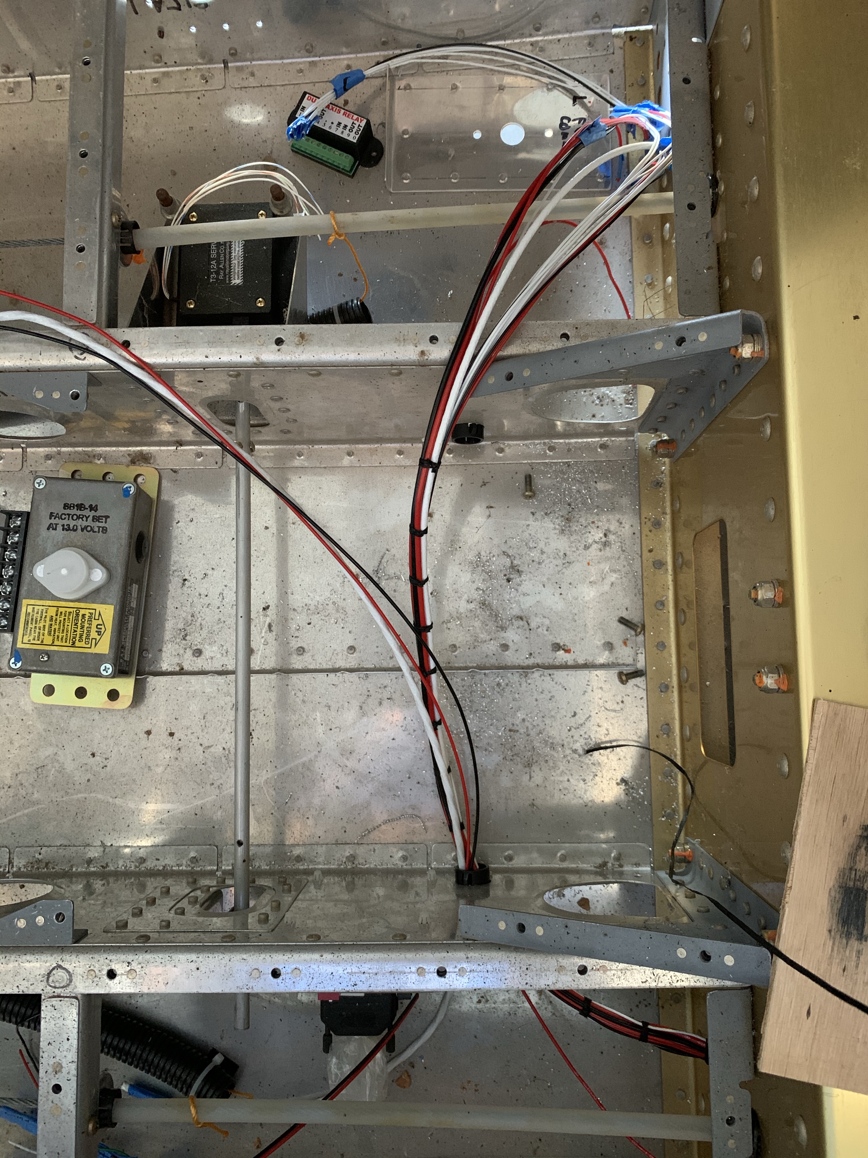
OK well, before I even consider whether that’ll reach, I really need to start with the stuff I’ve already terminated, which has no real room for adjustment. So I decided to get the upper shelf installed, route the harness where it needs to go, and see that all the connectors I added already will actually work out. And it looks like I’m in pretty good shape; some of the routings are a bit longer or shorter than I’d like in a perfect world, but they’ll work. I’m probably going to want to add some chafing protection in some spots, particularly where the main network trunk cable is going to be touching the edge of the CPI2 controller.

Also, I think I’ve decided that I don’t like my fancy ground bus clamp thing I put together a few days ago for the intercom. I think I’m just going to use a short screw and nut to tie the ring terminals together, and cover the whole thing with heat shrink.

Anyway, here’s a look at some stuff actually hooked up:


I guess tomorrow I’ll see about that bundle that bamboozled me earlier. I figure my next general move should be to verify that the harness stuff at the aft avionics shelf also reaches without issue. Everything else should be relatively straightforward outside of that.

Also, I’m going to rework the conduit runs back under the baggage compartment. I attached the conduit ends with these little zip-tie pads, using 3M VHB tape. For reasons I don’t understand, these pads have stuck just fine in the forward spots, but at the aft ends they’ve come off multiple times. So I think I’m going to see about pop-riveting the zip tie pads to the baggage ribs instead; they have little holes that ought to work for this. That’ll be something I want to fix before pulling the harness through the conduit.

Posted in Avionics, Electrical, Fuselage | Hours Logged: 1

Harnesses: routing stuff through the center section

Hard to believe I spent an hour and a half just finishing pulling wire bundles through the spar center section, but such is life. I worked on very carefully unwrapping the taped-up section that hung me up on Monday. There were a couple reasons for this – for one, some of the bundled-up wires have tape flags to identify them, and losing those and mixing things up would make life kinda interesting. For another, some of the spots I tapped were to indicate where branches were supposed to go off. Losing that reference wouldn’t be such a huge deal, but still something I wanted to avoid.

It turned out hat taped-up portion was only harboring three wires, the power/ground/disconnect leads for the autopilot roll servo. As I figured, it was easy to free their loose ends and then pull them through the spar separately. With that part settled, I finally finished pulling the main bundle through the spar, and got the snap bushings (which protect the edges of the passthrough holes) worked into place and installed. I also reinstalled the silicon-tubing protection on the gear tower penetration, which had come off when I was fishing stuff through the first time.

Next up was the secondary bundle that needed to go through the spar. This was the stuff I had to split off previously because everything wrapped together was just too bulky to go through one hole. I’d figured this would be the easy part, since it was a relatively small wire bundle, but…nope, not at all. Working from outside the fuselage, I just couldn’t get into a position to feed them through, so I resigned myself to having to work inside. A bit of a hassle since there are no floors in the fuselage right now, but nothing that can’t be “solved” by the strategic use of scrap lumber:

It worked, but wasn’t exactly comfortable. It did, however, provide an opportunity to take a photo illustrating the glamor of homebuilding:

That photo was taken after I realized that even wiring inside, I couldn’t fish the loose wire bundle through. The wires want to curve since they came off a spool, making it impossible to blindly fish them through two small holes about 6” apart. So I got Josie to bring me a roll of masking tape and, while lying on my wonderful lumber mattress, I carefully bound up the whole bundle. With that done, I was finally able to get it fished through:

I also spent a bit of time untagging the rest of the main bundle here and essentially figuring out all over again where things were supposed to split and branch. Next up, I get to take all the wires I removed for this routing expedition and add them back to the bundle, before moving on to the next big fun of pulling the bundle through the conduit to the tail. Except first, I still have to do my new riveted anchors to the baggage ribs.

Realistically, though, I think before I do that I’ll finish at least the rough routing under the seat floors. I need to make a couple holes in the center seat ribs for a small run over to the left side of the aircraft; that branch will serve few different things: the rear stick wiring, the roll trim servo, and the left wing disconnects. I figure if I can get some organization done in this area, it’ll maybe simplify and clarify what needs to be pulled through the conduit.

I’ve also been thinking through where to go once I get the main thrust of this wiring stuff done. My engine is still very delayed due to supply chain issues that Titan is having, but after talking with some other builders it sounds like it makes sense to work on some of the upper fuselage stuff ahead of hanging the engine anyway. So maybe from here, I can get the top skins at least clecoed in place, and then start working on the canopy. I figure I’ll also reattach the empennage along the way, and eventually transition into a life of fiberglass work. I guess I also need to decide at what point I should get this thing standing on the actual gear legs.

Posted in Avionics, Electrical, Fuselage | Hours Logged: 1.5

More harness routing

Not a ton to report tonight. I took care of securing the aft ends of the conduit runs to the baggage ribs, so those should be squared away now. Then I looked at allowing for routing wiring across the fuselage under  the seat floors; this is needed to get my left wing connections in place. I just drilled 3/4” hols through each of the indoor seat ribs and added snap bushings.

At that point, I figured it was time to go ahead and get the wire bundle routed over to the left side. So I started lacing it up starting at the spar, got it routed through the first snap bushing, continued lacing the part between the ribs, right up to where the rear stick run needs to split off. Then I realized my mistake – this run isn’t complete. These were a couple of the wire runs I removed to allow for routing through the spar…so I needed to add the left nav/strobe and flap control wiring. Which means I’ll have to remove and redo all this lacing. Not a huge deal, but still annoying.

I think what I’ll do for this next bit is go ahead and terminate the shielded wire runs from the nav/strobe controller board. All three of those were among the stuff I temporarily removed, so I can do this work on the table instead of inside the fuselage. Then, I figure with those bundles already terminated, working out the rest of their routing will be a bit easier.

But hey, here’s a look at the bundle I routed across the fuselage before realizing I’d jumped the gun:

Posted in Avionics, Electrical, Fuselage | Hours Logged: 1

Light controller termination, more routing

As mentioned last time, after realizing I’d forgotten to re-add some local wire runs, I decided to work on the nav/strobe controller plug outside the airplane, since the three output lines were all local. These are shielded wire runs to the wingtip and tail lights, so I got to work with the solder sleeves and shield terminations and such. Then I just had to terminate the ground and two switched power wires (for activating the nav and strobe functions) inside the fuselage, and finish up assembling the connector.

I was a little worried about whether this short branch might interfere with the right passenger footwell, but after a bit of thinking, it should be positioned well by the main trunk once that gets routed into the conduit:

Next up, I worked on redoing the branch that crosses over through the seat ribs, the one I laced up last time out before realizing I forgot some stuff. I got to remove the old lacing and rework this one, but once that was done I got the pertinent part routed through the second seat rib:

The harness splits here into two branches: the part that doesn’t go through the second rib is the branch to the rear control stick. The rest is stuff in the left bay: the roll trim servo, flap control relay deck, and the left wing connections.

One thing I’m realizing is that I probably need to clean out the fuselage and get it back on the rotisserie. Leaning over the side and doing this work isn’t really a whole lot of fun, and there’s plenty more termination and lacing to be done. I think from here I’m going to work in lacing up the right wing connection branch, and once that’s started, I should be ready to bundle up the remainder of the main trunk and get it pulled through the conduit.

Posted in Avionics, Electrical, Fuselage | Hours Logged: 2.5

Conduit run complete

Picked up tonight with some more cable lacing. This time I completed adding some of the previously orphaned wire runs to other bundles, and put a few laces on the stub for the right wing. At that point, I decided it was time to address the big fun of running the trunk through the conduit.

I spent some time looking at the length of the trunk, ensuring that every wire ends was wrapped with tape so there’d be nothing to hang up inside the conduit. In a few places some of the wrapping I’d put on previously needed to be removed and tweaked a bit. The one part I was a bit concerned about was where the trunk splits at the rear avionics shelf; I had those two branches taped off individually for organizational purposes, but that meant that when combined, I’d have a fatter bundle than I could otherwise get away with. But I liked this better than having to carefully re-separate those two bundles after pulling.

Just for more fun, as I was attaching my pull string to the end of the harness at the forward end, I pulled the aft end of the string into the conduit. I still haven’t tied those off at the aft end, a decision that finally came back to bite me. Still, it wasn’t a huge deal to fix – just like fishing the string through the first time, I pulled it out, tied the end to a cotton ball, and blasted it back down the tube with compressed air.

Pulling the harness itself was surprisingly easy. Things got a bit stubborn when the fattest part of the trunk was going through the conduit, and it took a decent bit of tugging, but overall it worked well. The only real casualty was that one of my retainer pads up front pulled loose of the 3M tape it was stuck to. That should be easy to fix, though, and honestly I could probably do without that particular pad if I wanted to.

In any case, everything’s looking a lot more tidy behind the spar now. Getting the trunk routed shifted the wingtip light controller branch over just like I thought it would, so it’ll be out of the way of the footwell. All I have left to do in this area now is to add the terminations for the wing connections:

Posted in Avionics, Electrical, Fuselage | Hours Logged: 1.5

Tinkering with aft wiring

OK yeah, it was a super short session tonight, but something is always better than nothing. Been on the go most of the day but figured I’d do battle with the mosquitos for a bit after dinner.

Basically tonight was about answering a simple question whose answer might have unpleasant consequences: did I leave enough length on these wire branches for the stuff back here? I found up front that while everything reached, the “extra” length I added actually made stuff reach kind of almost perfectly. And that made me wonder if it only reached because I pulled more slack on the main trunk itself.

In short, I was more than a little nervous as I gradually peeled away all the masking tape that had been wrapping the assorted bundles together back here. The first good sign was when I pulled the pitch trim and tail light wires back through to the tail, and found I had several feet of slack. Then I split off the branches that go under each of the rear seat armrests – one for the headset jacks and power plug, another for the seat heat control and flaps. Plenty of slack there, too.

That left the real fun stuff on the avionics shelf, aaand…it all looks good. I wouldn’t have minded an extra inch or two on the ELT branch, but it’ll be fine. and the other branches for the other devices have plenty of length. In fact, the branch for the transponder will probably need a few inches trimmed off of it.

Here are all the branches sort of mocked up to their components. This photo doesn’t exactly look super organized, but I promise it shows good things:

The question now is what to do next. I really want to get in there and start doing some lacing to make this look nice and clean, but I think the smarter call is to final-trim and terminate these branches first. That won’t be a ton of fun working inside the fuselage, but such is life.

Another thing I want to get on sooner rather than later is installing the ADS-B and transponder antennas. The coax runs for those will need to coexist with the wiring both back here and under the seat floors, so I think I ought to go ahead and get hose done now as well. I’d kind of like to do the same for the comm antenna runs, but seeing as how those antennas are a lot larger, I don’t like the idea of installing those until the airplane is on the gear. Seems to me like they’d be a bit too prone to damage. Though now that I think about it, I could temporarily install them long enough to get the coax runs worked out, then remove them until it’s time for final installation.

Anyway, I guess I’ll pick up on this Monday. Tomorrow I’ll be helping with another project, in this case disassembling a plane so it can be shipped. Just part of the fun I get from working with the Waller County Aviation Museum. (SHAMELESS PLUG)

Posted in Avionics, Electrical, Fuselage | Hours Logged: .5

ELT connection

Things went a bit slowly tonight. I wanted to start with the ELT on the rear shelf, and while I’m super familiar with the connections for the Dynon stuff, here I felt compelled to look over the documentation a bit more. Also, whereas most everything else already has every required wire run to the location, here I needed to add in the ELT buzzer. This little guy will make lots of noise if the ELT is ever activated, and since I’d decided to just put it right beside the ELT, there was no good reason to include it in the prefab harness.

The buzzer I ended up just mounting with some high-strength velcro-type stuff. Thought about using screws but that seemed like unnecessary complexity here, plus the screw holes in the buzzer are super small and as far as I can tell there was no mounting hardware provided with the ELT. And eventually I had the whole thing put together and set up in place:

An interesting point here: this is one of the few spots in the airplane where I’m using a local ground; almost everywhere else, I’m running back to a single ground bus on the firewall. Since this ground is just for the buzzer and other basic stuff, I’m keeping it simple. Plus this made it easy to completely ignore the buzzer while building the harnesses. I’ll just secure the ring terminal with the adjacent shelf mounting screw.

Hopefully tomorrow I can do some of the other terminations here; I’ve got the ADS-B receiver, transponder, and the network cable to the hub. Once that’s done I’ll start seeing about how I want to lace up the cables here to make everything nice and tidy. I’ll also need to figure out securing some of these bundles; I think I want an adel clamp on the forward flange of the shelf, plus some way to route the wire branches going to the seat armrests and back to the tail. The latter is particularly interesting; I’ve learned while installing and removing the shelf a couple times that those two wires kind of get in the way. Hopefully some creative routing can help with that.

Posted in Avionics, Electrical, Fuselage | Hours Logged: 2

ADS-B receiver connection

Well, that was an interesting evening. Got a bit of a late start but figured I could make good progress on some of these terminations. Except about ten minutes into working on the ADS-B connector, we got a tornado warning. I figured monitoring the weather was more important than working on the airplane, so back inside I went. Turned out to be OK, cell passed west of us. So I went back out and got going again, but after another 10 minutes or so…tornado warning #2. This one didn’t miss us, and we ended up in the closet for a bit.

I was determined to at least get this one connector done, so I went out again afterwards and finally got it done. Thought about starting on the transponder connector too, but I need to think about some wire routing before I do that, so I contented myself with just pinning up the two loopback connections for that (pairs of pins that are tied together to enable the thing).

Pesky weather…

Posted in Avionics, Electrical, Fuselage | Hours Logged: .5