Electrical

Harness detail planning

This was a longer day than the hour count suggests; while I didn’t put it down as shop time, I spent several hours this morning running several parts orders. Some connectors and wiring supplies, both the charge ports I’m going to use, plus some other goodies like wiring tools and a 30A 12V power supply. Right now I only have a 10A supply, and I’m looking towards the time when I’ll want to power up a fair amount of the avionics at once, and 30 amps should do the trick nicely.

As far as shop stuff, I started out by ripping out all the fun stuff I installed yesterday. Seats are back in their box, floors and flap stuff are back on the shelves, and so on. Then I wanted to get the CO monitor box mounted on the baggage bulkhead. The spot I was intended worked out nicely, so I just had to drill a couple holes. Even better, I had enough spare hardware from previous work so I could mount this immediately without having to wait for anything:

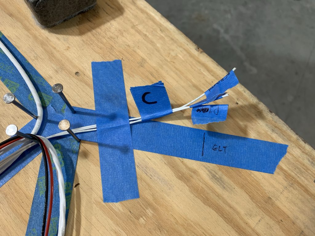
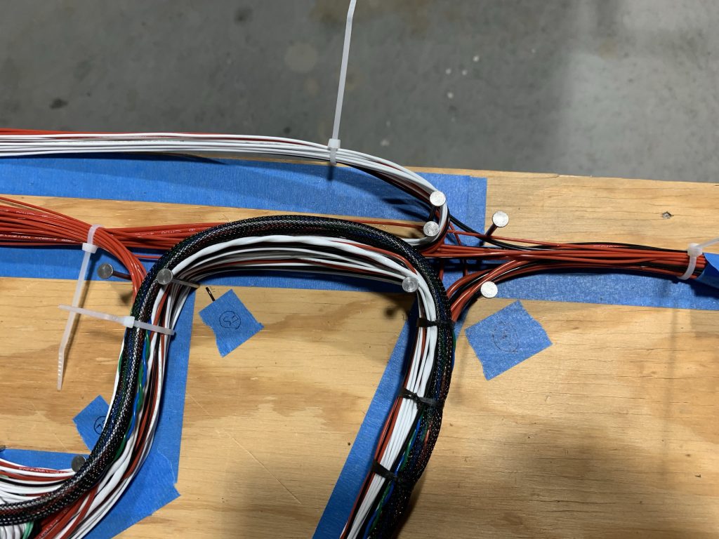
And then it was time to get down and dirty with harness planning. The overall intent was to take the line drawing I did a while back and 1) refine all the despited branches and groupings and 2) give each branch an actual length so it could be turned into a harness. The general idea for doing this was to run ribbon through the aircraft and use that to simulate wiring runs. I started by just running a single long ribbon along the longest continuous harness path – that is, starting back at the tail, going under the baggage compartment and seat floors, up the right gear tower, across behind the panel, back down the left gear tower, and to the firewall.

The original plan was to then add individual ribbon runs for various branches, but I decided that was overkill. Using that long run as a baseline, I marked up all the major junction points, and then made individual measurements along branches and to components and wrote those down. By using a tailor’s measuring tape, I could pretty well simulate curved paths branches might take. And at the end of the day, none of these branches need to be millimeter-precise or anything. While I’ll probably assemble the bulk of the harness on the table, I don’t intend to do any actual terminations to complex lacing until the whole setup is installed in the plane. So when measuring branches, I was just conservative with my lengths, with the expectation that I’ll trim to final length in place in the airplane.

The decision to terminate everything in place comes down to a couple points: first, I don’t really trust that I’ll get every measurement exactly right, no matter how careful I am, especially compared to seeing things in place. Second, since significant portions of this harness will have to be carefully threaded through the fuselage, I think it’s to my advantage to not lace a bunch of stuff up and compromise the flexibility of the thing. It remains to be seen exactly what the results of this decision look like…

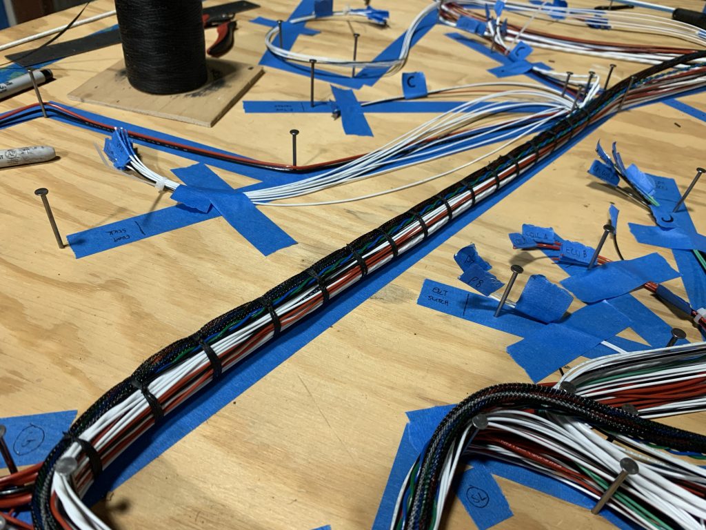
Anyway, after a whole lot of marking up my line drawing, it was time to pull the long ribbon out and take my last batch of measurements, between the various junction points I’d marked previously. Kind of impressive to see all ~20’ of ribbon stretched out in a straight line, though I imagine it’ll be even more impressive when there’s a wire bundle this long:

And for the final exhibit, here’s the heavily marked-up harness line drawing, which was the main product of today’s work:

Next up, I get to put together a similar layout on my big work table, which is where I’ll be starting to actually put things together. This is when the fun will really begin. I also need to take a final pass through my schematics, I have a couple punch-list items to address there before I actually start routing wires. I think I also need to make some final decisions on what my grounding scheme for everything will look like. I know I’ve planned to do local grounds out in the wings for the landing and taxi lights, but I think most everything else I’m going to end up taking to a single ground bus on the firewall. I should probably get rigorous with the schematic and give each ground-bus item a discrete tab label so I’m sure I’ve got enough terminals up there.

Posted in Avionics, Electrical, Fuselage | Hours Logged: 5

Harness board layout and beginning assembly

First order of business today was making a first pass at fine-tuning my schematics. I had a few small items not depicted that needed to be added; not strictly necessary to start wiring, especially since most of these items were kind of self-evident, but I’m really making an effort to be exhaustive with my planning here. I also wanted to get to identifying where each ground would actually go, but by the time I finished the detail work I was kind of tired of messing with the schematics, so I put the laptop aside and went to work out in the shop.

The main task of the day was obvious: I’ve got a not-at-all-to-scale line drawing of the harness, which needed to be turned into a full-size layout on my work table, using strips of blue masking tape for the wire paths. This will be the template of sorts upon which I’ll build the harness. Putting this together was just numerous hours of looking at my whiteboard diagram, staring at the table and trying to visualize how to lay everything out so there’d be no interference, and then just adding one strip of tape after another.

All in all, it took several hours to get what you see here, which is the completed layout of the harness. In an extremely broad sense, the tape line winds from the lower right (stuff in the tail), up to the upper right (representing where the harness will reach the rear avionics shelf), the proceeding down and slightly right to where it joins all the stuff under the seat floors (like the wing connections), then over to the right where the fun really begins with all the stuff behind the panel.

Also, just to ensure there’s proper scale here, remember that this table top is a full 4×8 sheet of plywood. Even taking this photo was kind of a challenge, involving standing on a stool and holding my phone as high as I could:

This didn’t quite complete the harness buck, though. Next up was adding nails at all the junction points, which is how the wires will be held in place as they’re wound along their paths. For this, I used some small finishing nails; as we’ll find out later, this was a poor choice. But i didn’t know it at the time, I just wanted to start stringing some wires.

Now, one thing that will make this harness fun is that I’m not building all this stuff up from scratch. Most notably, the harnesses for the CPI2 ignition are prefabricated, so they’ll have to be laid in amongst the other stuff, which might be fun. What makes this even more fun is that all the CPI harnesses are terminated at the engine end, so whenever this stuff is finalized, I’ll have to connect stuff forward of the firewall, and then work out the final wire lengths from there back into the fuselage. But that’s a ways down the road.

The point of all this is that the first thing I tried to do was lay in the CPI2 harnesses. I didn’t really expect them to stay permanently, but I did want to visualize how things would match up, and also validate that my rough-out of firewall-forward wire lengths was reasonable. Unlike all the other stuff here, I don’t know where FWF stuff will terminate, so I’ll just be leaving a ton of extra wire to be trimmed to final length later on.

The point of all this is that even just laying in those CPI2 harnesses, I had wires jumping off my little finishing nails. Obviously these were woefully inadequate. So after removing the CPI2 harnesses and packing them away again, I yanked out all those finishing nails and replaced them with some much larger cousins.

After staring at everything for a while, I concluded that there wasn’t much left to do but actually start laying in wires. I decided that my rough strategy here would be to 1) try to lay in the longest wire runs first and 2) work from the rear of the plane forward, so I could keep track of my work by labeling each termination as complete. That seems a lot better than trying to individually mark off each wire as I run it.

I didn’t really end up doing a ton here, because I kept running into questions to answer. Maybe the biggest oopsie was when I ran the 18-ga shielded bundle from the tail to the nav/strobe controller – after I’d cut it to length, I looked at the remaining bundle and thought it looked way to short to still be able to route from the strobe board out to both wingtips, and that was a good hunch. Apparently when I ordered this stuff I only accounted for the wing runs, and forgot about the tail light. Thing is, the tail light doesn’t even need three conductors (like the bundle I’d laid in), just two. The good news is that I quickly found a source for two-conductor shield bundle, which I’ll use for the tail light, and that original bundle will still be usable for my wingtip light runs.

In the end, I just laid out the pitch trim cable, cables from the rear-seat headset jacks, and connections from the ELT to the panel. I think things will begin to speed up from here; for one thing, I’m getting more confident in pulling and cutting wires (this is essentially confidence in my planning), and I’ve also worked out some other details, like labeling the ends of each wire temporarily with blue tape.

And while it’s not a lot, it’s still cool to see the beginnings of a harness start to take shape:

Instead of laying any more wire in tonight, I’m going back to my schematics to nail down those ground locations – that’s one of the things I need to get nailed down so I can continue, because some of the long runs from the tail I want to make next are ground runs.

I’m feeling really good about this stuff right now, though. Way back when I was first working out schematics, I was looking forward to doing the wiring, but kind of wondered if I’d still feel that way when I got into it. It’s still early yet, but I’m actively enjoying myself so far. Over the past few days I’ve been keeping my expectations low, thinking that maybe I could make some good progress on the wiring during my vacation, but after today I think I have a fighting chance of having this harness in the plane before I go back to work…which would be quite a victory indeed.

Posted in Avionics, Electrical | Hours Logged: 6

Harness assembly, continued

Another solid day’s work, and good progress in spite of a couple roadblocks. I was in a good place to get rolling (after a morning appointment) because I took the time last night to go through the schematics with a fine-tooth comb. I got all the grounds depicted properly, and corrected a few other items as well.

I decided my first order of business would be to run the power and ground wires to the rear-seat charge port. Doing this would allow me to close out that particular branch, and I’m going with a strategy of trying to close branches out whenever possible. I figure the fewer incomplete branches I have, the less chance there will be that I’ll mess something up or forget a wire.

This ended up being a rocky start to the day. The power and ground runs to the charge ports are 18ga, and while the power run was fine, by the time I finished the ground run…I’d used the majority of the 18ga black wire I had on hand. This was pretty obviously a problem; what I had left would be barely enough for the other charge port’s ground and the short airframe grounds out in the wingtips. I knew good and well I had more circuits that merited 18ga grounds, and a review of the schematic proved that out.

Even more annoying, the very next branch I was going to work on – the runs to the flap motor – also need 18ga wire. So this problem was directly affecting me almost immediately. I started to go ahead and place another wire order, but pretty quickly imagined myself just ending up making an order per day for the rest of the week and paying out the nose for repeated shipping costs. So I decided to pause for a bit, take inventory of the wire I had on hand, and work out more precise estimates of what I needed.

Basically, I just wanted to see that what I had on hand was generally well in excess of what I estimated that I needed. I’m sure I didn’t catch every single run in this really hurried estimate, so ample breathing room was what I wanted. In the end, I found I was OK on everything except 22ga black…where my usage estimate exactly matched my inventory. Yup, that ain’t gonna work. So I placed an order for the 18 and 22ga wire, and after thinking it over for a couple minutes, I went ahead and sprung for next-day shipping. I really want to stay productive during this vacation time, and I’d rather drop an extra $10 or so on shipping to that end.

With that minor crisis handled, it was time to see what I could do next. The flap runs are pretty straightforward, so I decided it’d be OK to move on to the other stuff on the aft avionics shelf. In the course of this, I worked out some more work habits to use to help me stay organized; first up was clearly marking any branch that was complete. For this, I just made another tape flag with a big “C” on it and wrapped it around the entire bundle. I also removed the spring clamps that had been holding that branch, and taped the bundle down. Since these clamps are in kind of short supply, being able to “recycle” them is pretty important.

An example of a closed-out branch (in this case, for the ELT):

The next fun items were the transponder and ADS-B receiver. In addition to power and ground runs, these both have serial data connections to the HDX displays – something I hadn’t had to work with yet. Making these more fun is that these serial connections need to be shared by both displays, so instead of a simple point-to-point run, I needed to work in splits near the displays. To do this, I got to teach myself how to do window splices, something I’d be pretty good at by the end of the day. This is just where a small piece of insulation is removed from the main wire, and the stripped end of a second wire is wrapped around it, soldered, and finished with heat shrink:

So now that transponder and ADS-B branches are closed out, and I’ve also gone ahead and run the power/ground/disconnect wires for the pitch servo (and also added window-spliced branches for the roll servo while I was at it). This makes the tail section of the harness pretty much done; the one thing I can work on right now is the network cable to connect the front and rear hubs, but other than that I’m waiting on the wire orders for the flap and tail light runs.

So now I’ve got a little more color diversity to the harness:

I’ve already been thinking a bit about how to move forward tomorrow even before the wire orders (hopefully) come in, and it looks like I can reasonably start working on some of the mid-cabin stuff – the remainder of the wing stubs, beginning the stick function wiring, front seat heat/headset jacks/charge ports, and so on. So while I’d really like to wrap up those tail runs, I’ve got plenty of room to keep going. It may be a bit optimistic – I’ve still got the complex behind-the-panel interconnects remaining – but I may even have all the wires laid out this weekend. It’d be really great to start temporarily building this stuff up and be ready to try stuffing it into the fuselage next week. Will that happen? I dunno, but hey, even if it doesn’t, I’m already feeling great about the progress so far this week.

Posted in Avionics, Electrical | Hours Logged: 6.5

Harness assembly part 3

No photos today. I could have taken another photo of the harness as it stands now, but at this point I think it’d just be “here’s a slightly different-looking pile of wire.” I’m starting to feel like I’m reaching maximum chaos here; like I still have my head wrapped around what’s going on on that table but it sure doesn’t look clean and organized. Anyway, that’s probably enough existential musings for the time being.

Really, there’s not a lot to say other than I kept going. I built out the main backbone network cable that connects the forward and aft network hubs. I got the network data lines put together and run out to the right wing root connector branch. In fact, I got both the wing connector branches closed out completely, along with the front stick grip (all eleven connections) and front seat heat feed. At this point, almost everything aft of the spar is complete; all I have left back there is the run from the flap relay to the flap motor (waiting on the 18ga black wire I ordered) and the tail light run (looks like that cable won’t be here until Monday).

I think tomorrow I may pause from laying in wires to try and impart some organization to what’s already on the table. Aft of the seat pans, everything is in pretty good order, since I was laying in from that direction for the most part, though it could probably use a once-over with a cable comb. The under-seat stuff is in decent shape as well, but could use a bit of attention. What I really want to work on, though, is the rest of the harness, up around the panel area. Starting from the rear has meant that I’ve brought in lots of wires piecemeal, so they’re all sort of crossed up. Since I’m rapidly approaching the point where I’ll be working on the really complex stuff behind the panel, I want to start with things as organized as possible.

Put another way, I don’t want to wait until every wire is laid down before I try and bring some order to the chaos.

Additionally, I had another thought today. I’ve been sort of idly trying to think through what the procedure for getting this harness into the airplane will be like. My main concern all along had been getting the harness to the tail worked through the conduit under the seat, but today I realized I’ll have much more of a problem getting this thing through the spar center section. The conduit shouldn’t be much of a problem; essentially, every wire aft of the conduit starts on the forward side, which means the entire aft harness can be at least temporarily consolidated into a single thick cable.

Under the seat floors is a different matter; I’ve got wires crossing among a few different boxes here, like the nav/strobe controller and the flap relay. What this means is that the harness is going to be fatter aft of the spar, which may complicate feeding it through from the front. And I have to feed it through that way because otherwise I’d be stuffing the super complex panel harnesses through, and that’s a no-go for sure. So far my plan is to temporarily remove all the “local” stuff under the seat floors from the main harness before I install it in the fuselage; it’ll be a bit on the annoying side, but I don’t think there’s any way around it.

That’s a problem for another time, though; for now I just need to get things really finalized and cleaned up. Too bad I’ll likely have to wait until Monday for the harness to be complete, no matter how much progress I make over the next couple days. But I can still focus on finishing up and organizing the panel section; the tail portion should be a relative piece of cake after that.

So…until tomorrow…

PS Also, if I sound a little bit down here, I’m not. I’m still enjoying myself, just being cognizant of the challenges in front of me. At the end of the day, I’m overjoyed with how well this is going. I’ve heard folks talk about spending months getting wiring done, and here I feel like I’m on track to do it in a few weeks. Granted, there was a whole ton of planning effort ahead of this, but still…I’m feeling very accomplished right now.

Posted in Avionics, Electrical | Hours Logged: 6.5

Harness assembly part 4

Another solid productive day. My ground wire order came in, so I was finally able to get the wire run back to the flap motor done, which allowed me to close out a couple more branches. If it weren’t for that pesky shielded wire for the tail strobe (which won’t be here until Monday), I’d be able to close out the entire aft section of the harness. Oh well…

The overall strategy for the day was to work from the ends of the harness inward towards the panel. I’ve already been doing this from the tail direction, but today I started working in from the other end of the harness as well. That end is comparatively simple, just the fuel pump, left tank sender, and ground bus. The idea is to finish up all the runs that start outside the panel and go in, and then I’ll finish up with all the runs between panel items.

The strategizing did cost me some time today, though. One thing to consider was the connections from the displays to their backup batteries. The battery connectors are preinstalled on the harnesses that came with the displays; while I’m going to mostly rebuild the harnesses with my own wires, I figured I’d reuse the battery connectors. But were the included wires long enough? Well, I’d better go ahead and disassemble one of the display harnesses and find out.

Turns out they’re definitely too short. So I started thinking about just making my own battery connectors; they just looked like regular old micro molex plugs to me. I went to the install manual to see if they specified the connector, and sure enough, it was a molex. But I also noted an important commandment regarding the battery connections – the runs were not to exceed 24” in length. If I ran these through the service loop from the center panel to the avionics shelf, I’d be far in excess of that.

So, new decision for the day: the battery connections will be separate from the main harness. There will still be enough slack in them for me to remove the center panel and have a decent service loop, but it’ll annoy me a little bit.

There were a few other considerations as well. I discovered that I never added the Aithre Shield CO monitor to the EMS schematic. Easy enough to do, though. Then there was the question of getting the audio output from the CPI2 ignition controller to the intercom, so I can have audible alerts if there’s an ignition fault. The CPI came with a short audio patch cable, but 1) it’s too short to go from the CPU to the intercom and 2) it has plugs on both ends. I need bare wires on the intercom end. I ended up ordering a cable with only one termination from Amazon for this purpose.

So yeah, lots of research and thinking, but I still got plenty of actual wiring done. At this point I’ve basically closed out everything outside the panel/avionics shelf area; I did the rear stick branch, both fuel level senders, the switch group on the left side of the panel, and the main switch console on the right side of the cabin. The only things outside the panel that aren’t closed out (besides that pesky tail light) are the power and ground buses, as well as the branch going to the engine compartment.

The plan of attack for tomorrow will be to first route the power and ground connections for everything in the panel, then close out the EMS harness, and finally start doing all of the inter-panel connections. We’ll see how far I can get with that. I suppose I’ll also want to go through the entire constructed harness and verify that I didn’t miss anything important…that’ll be a chore in itself right there.

For now, I’ll throw in some more photos. Here’s the overall state of things; it looks pretty chaotic, but it’s kind of hard not to with all the spring clamps and stuff lying around:

And for fun, here’s a close up of the busiest part of the harness. This is the area just to the right of the panel/avionics shelf, so in a sense everything passes through here. It’s the wiring equivalent of an interchange between two super busy highways, except here it’s more like three highways and two smaller roads. This is going to be one fat bundle of wire when it’s all laced up:

Posted in Avionics, Electrical | Hours Logged: 7

Harness assembly part 5

Whew. Well, I didn’t get all the rest of the wire laid in today like I’d hoped, but I’m getting really close. To just summarize at the beginning here, all I have left to do is to connect audio out from the Skyview displays to the intercom, run a dimmer control connection from one display to the intercom, and put in the stub for the Skyview GPS antenna from the displays.

I kind of thought about trying to push through and get those done tonight, but all but one of those connections will involve window splicing, since the displays get tied together. I’d rather save that for another day. Plus I’m not quite sure how to handle the audio output; best practice would call for using a shielded bundle for something like this but I dunno how to handle the split between the displays with that. Something to stew over before I commit, I suppose.

So that’s what’s left. I only closed out a few branches today but some of them were big ones; for example, the EMS branch (27 pins), the main/essential buses, and the FWF stuff (mostly the other ends of those EMS pins). The latter two didn’t just have a bunch of conductors, they were also super long runs and really fun to manage on the table as I kept adding to them. I was glad to be able to bundle them up permanently so they won’t keep sort of springing apart and throwing wire ends everywhere.

There was also some more thinking to do; for one thing, I got down to working with the CPI2 ECU branch, which is where I’ll need to add in some existing harness stuff that came with the CPI2. In the end, I did as little as possible here; really just the RPM output wires to the EMS and the ground runs. Everything else I’m going to add once this is in the plane, otherwise it’ll make this harness work an order of magnitude more messy. Some of this is unavoidable; for example, the coil and crank trigger harnesses are already terminated on the engine end, so they’ll have to be fed through the firewall and into the cabin, the exact opposite direction from how I’ll be feeding the big harness. The other pertinent runs are those to the physical panel switches, and since those will be very short and virtually point-to-point, it seems better to just do them in place.

I did get one unexpected surprise today. My neighbor Leonard, a veteran builder and tech counselor, happened by on his golf cart and stopped in to take a look at the build. It’s always nice to have an experienced set of eyes stop by and not scream in abject terror at my workmanship.

Welp, that’s it for tonight. More to come tomorrow…

Posted in Avionics, Electrical | Hours Logged: 6

Harness assembly part 6

Today wasn’t quite as productive as the previous week has been, but I think that’s OK. Some of that was just relaxation, but there was also some other work to be done around the house. Still, I managed to get over the sort of chaos hump and I’m now on the road to order. I think…

Things again seemed deceptively simple today, with just a few items left to close out. And true enough, most of it was simple; four wires to the Skyview GPS, split to both displays, a dim control lead from one display to the intercom…and then that pesky audio connection. To review, the Skyview system needs to output audio to the intercom; this is for assorted audible alarms, AoA indication, etc. What’s fun is that the install manual calls for the audio pins (left/right/ground) of both displays to be tied together and connected to the intercom.

As mentioned yesterday, normally a nice shielded wire bundle would be used here to avoid noise. But making a split circuit out of one of those would be interesting, and probably bulky in the harness to boot, especially since I’d want to figure out some way to tie all the shields together. I could skip tying the shields, but at that point why bother with the shielded cable at all? Maybe I should just run three wires and be done with it. But what if, in doing so, I condemn myself to a buzzy intercom (and/or the fun of trying to figure a fix after the fact)? I should just do the shield, obviously…but how do I tie it together?

I spent an absurd amount of time going round and round this circle in my brain. At one point I tried an idea of tying shield wire together at a single point (vs the window splices I’ve been doing). Can I fit two of these tiny wires into a D-sub pin? Nope. Hey, what if I strip one wire long, crimp the pin on, then wrap and solder the second wire just above the pin? Can I still insert it into the connector? Yes, but the soldered part goes inside the hole. Cal I extract the pin? Um…..no, I cannot. Well, not only is that idea a bust, but now I have a D-sub connector that’s unusable. Good thing I bought extra.

At some point it occurred to me to look at the prefab display harnessed I have. How did they do it there? I don’t recall seeing a shielded bundle in there. Yup, they just have the three wires in there, though they’re twisted together, which I suppose is sort of a middle ground between my two options.

Finally, I gave in and made a post on the forums. This was pretty classic analysis paralysis, I just needed some sort of shove in the right direction. And I got it…just one guy saying “use the twisted bundle, I’ve done this in several installs and it’s fine.” So I did that. I extracted the three-wire bundles from both my harnesses and did my usual window splice thing to tie them together.

At last, I had all the wires in there! Well mostly, I still have the CPI audio cable and tail light wire that’ll come in tomorrow, but…close enough for celebration, right?

I really wanted to move right on to starting some cable management, but I forced myself to stop and go through a QC check first. I wrote down every single branch on the whiteboard and went through every one and verified that I had the proper number of wires and that they at least looked right (ie power vs ground vs signal). If I’d wanted to be really thorough, I could have verified all the pin designations, but that probably would have taken a ton more time. Given that I verified each branch before closing it out the first time, I felt this was an OK compromise.

That meant it was time to get down to the real fun…starting to take this table of chaos and turn it into something orderly. Which meant breaking out the cable lacing and getting to work. I need to work out an overall strategy for how to approach this, taking into consideration the need to fish this into the fuselage at some point…but I’d at least thought this through enough to know that I was going to start with the wire run up through the right gear tower. In my mind this is the run that will anchor everything else.

Also, this bit of lacing made for a nice capstone to the day’s work…it sure is satisfying seeing things come together like this:

But that was the easy part. The next question is, how much lacing do I do on the table? Once these bundles are laced they become relatively inflexible, which 1) will make fishing them through the fuselage more challenging and 2) be problematic if I lace them up and they’re bent all wrong. And there’s at least one spot where my tape layout was a poor choice for preparing for lacing, right here at my Spaghetti Junction:

At issue here is the “crossroads” on the right side of the photo. This is indeed a four-way junction, but this orientation is wrong. The bottom branch in the photo will go down the gear tower and eventually aft, the upper one will go forward to the firewall, the right one will go aft to the switch console, and the left one will continue up before splitting between the fuse shelf and avionics shelf/panel.

Basically, I need to figure out some way to rearrange this junction before I lace anything else around it. Which will be fun, because it means rearranging a complicated branch, regardless of whether I decide to move the aft branch or the one going to the avionics shelf/panel. So far the best idea I have is to start working through the aft portion of the harness – I have to work out how to bundle this to go through the spar and conduit anyway – and if I can get that all bundles up in some temporary fashion, I think I’ll be able to see about moving it as a unit to get this intersection reworked as needed.

Yeah, we’ll see how that goes.

There’s also some prep to be done in the fuselage for running this stuff. I need a hole in the gear tower going forward for the FWF bundle, and I need to cover the edges of some other holes in the gear tower the bundles are going through. Those holes are too big for snap bushings, so I think I’m going to take some of my ample surplus of nylon pitot line and turn it into a split edge protector.

Oh, and more decision info: previously I was intending on not really terminating anything on the table, but rather getting this thing installed into the fuselage and doing all my final trimming and terminations in there. The more I think about that, the more I don’t like it. That’s a whole lot of wire stripping and crimping while hunched over the fuse and/or working in a tight space (such as behind the panel). Some of this will be unavoidable – the stuff aft of the conduit run ones to mind – but at least that’s a relatively small amount of termination. I’m really thinking of all the behind-the-panel stuff.

So for now I’m thinking of actually pulling the harness through the spar and conduit, massaging all my various branches and trimming them to final length, and then pulling the harness right back out. That way I can do most of then tedious termination on the table. Given the importance of 1) making those terminations nice and 2) getting all the pins in exactly the right place, I think it’ll be worth the extra effort.

But that’s all several steps ahead. There’s plenty to do before I make those decisions. Which is what tomorrow is for.

Posted in Avionics, Electrical | Hours Logged: 4

Harness assembly part 7

So, today’s main focus was on preparing for putting this thing into the airplane. That’s not necessarily to imply that I’m really close to that point, but more that I wanted to try and identify any potential issues. First and foremost was the question of whether I could feed this thing through the spar center section, and that was what most of the early-day stuff revolved around.

To start with, I just began pulling the harness up from the table. This entailed temporarily bundling up some of the branches, more than I had before; I used a bunch of small zip ties for this. I also made sure that each branch was labeled so I’d know what it was. In some cases I put this info on individual wire labels, but I wasn’t consistent about it.

The real fun came with the harness portion behind the spar. My general plan of action was to remove from the harness anything that was behind that pass-through, and didn’t go through did pass-through. Basically I wanted to slim down that section as much as possible. Next, I took the branches from behind the spar, and worked them in alongside the main trunk. I used masking tape to wrap each junction so I could restore this stuff down the line, and also extensively wrapped where these wires laid alongside the trunk – especially where the ends of the wires pointed aft. I wanted to provide as smooth of a profile as possible.

Once that was done, I grabbed a snap bushing of the same size used in the spar passthroughs, and started trying to slide it along the bundle, working from the tail forward – basically simulating feeding this thing through the fuselage. Unfortunately, it didn’t go too well – once I hit the ends of some of those runs under the seats, the bushing just wouldn’t move any more. I actually had to cut it off the bundle to get it off.

So, what to do from here? I considered emailing Van’s to see if it was permissible to enlarge the passthrough hole a bit. I figured going up from 3/4” to 7/8” would give me plenty of room. But when I checked Spruce to see if they had the larger snap bushings…nope, the biggest they have are what I already have.

Fortunately I’d already been considering a plan B. There are actually two passthrough holes in close proximity here; my plan had been to use one for the wiring bundle and the other for one of the com antenna coax cables. What I’m going to do instead is split the harness just forward of the spar. There’s a convenient branch for this; all the stuff that goes across the fuselage to the right wing root should work well, since 1) it already has the length to reach over there and 2) all of this stuff has slack built in, and the connecting harnesses can be lengthened if needed to fit (when I make them).

So after redoing my wrapping for this idea, I decided it was time to try putting the harness into the airplane. I decided not to deal with maneuvering it through the spar for this temporary installation; the main thing I wanted to do was verify that the runs behind the panel were long enough. With that confirmed, the plan would be to go ahead and terminate all these on the table.

And so, after a whole lot of wrangling, muttering, and other questionable activities, I had the thing in place:

The harness doesn’t look too great here since it’s not laced up at all, and in general it’s kinda messy. But the branches reach their devices without issue, so this should be good to go. So…I pulled the thing right back out.

One thing I learned while doing this is that my idea if the upper shelf bolts also holding adel clamps to secure the bundle is…not a lot of fun. For one thing, I don’t have adel clamps big enough to wrap the root of this harness. Second, it’s a huge pain trying to start those bolts through a clamp that’s wrapped around a wire (I did this for the center bolt). Pretty sure if I stick with this, I’ll have massive regret the first time I have to pull the shelf. So I think I’m going replace the adel clamps with simple plastic wire guides; since these aren’t intended to hold the wire tight, they should be easier to work with.

Anyway, with the harness back on the bench, it was time to get back to lacing. This is a little bit fun; I really shouldn’t lace some of these junctions, since some runs from the engine compartment won’t exist until much later (like the CPI harnesses or the thermocouples for the EMS). But the lacing needs to proceeds in an orderly fashion to make the bundles nice and neat…so I’m lacing everything, even though I know I’ll have to cut some of these off down the road.

That’s where I finished the night, after lacing up the trunk across the upper shelf. Tomorrow I figure I’ll keep lacing, getting to the service loop and trunk to the panel, and then…I guess it’ll be time to start building up some connectors…

Posted in Avionics, Electrical, Fuselage | Hours Logged: 4

Harness assembly part 8 (connections!)

Didn’t have quite as much time in the shop today, mainly due to some other obligations that included driving out to Hobby to pick up Josie (she’s been visiting family in Atlanta). I did find the time to finish lacing up the panel portion of the harness, and then I decided there wasn’t much else to do but start terminating stuff. I started from the very end of the panel service loop, and got the connectors done for the radio and autopilot panels.

The radio connector was pretty easy – just six pins in a 15-pin connector – but the autopilot also had a 15-pin connector with only one vacancy. That one was a bit less fun. It’ll be really great when I get to the 37-pin connectors for the EMS and HDX displays. At least the latter are somewhat sparse, but I can’t say the same for the EMS…

Oh well, it’s still looking more and more like a real live wiring harness:

Posted in Avionics, Electrical | Hours Logged: 2.5

Harness assembly part 9 (more connections!)

I don’t have a lot in the way of introductory text to put in here, much as I might like to do my usual summation. I started off today by moving on up the harness to the first of the Skyview display connectors. One new thing to work with here vs the connectors from yesterday was the need for split power/ground leads. The Skyview displays have two pins each for power and ground; not for redundancy or anything, I guess just to distribute the current a bit or something.

Whatever the case, when I pulled the harnesses, I just pulled a single power/ground pair to each connector; that meant that today I needed to do a couple window splices for each connector to get the split. Since I was already using printable heat shrink to mark each wire, I just positioned the tube for these wires to cover up the splits.

Hey look, a nice little forest of D-sub sockets!

These connectors are also unique in that they’ve got a couple prefab items attached. From the prefab harnesses that came with the displays, I’m reusing the backup battery connectors, as well as the USB connectors (these are used for software updates and such). So I had to de-pin those from the original connectors and add them to the new ones I was building up. For now, those leads are just sort of hanging out on the table. The battery leads will stay that way (though I may lace them together or something), but I’m not quite sure about the USB leads. My general intent is to just have them hanging behind the panel where I can grab them if needed, so I’ll figure out the details of that once I get this harness into the fuselage.

Also, I probably should have gotten a photo of a completed connector, but oh well. Just imagine the ones from yesterday, but bigger.

Next up, the real fun: the connector for the Garmin GPS-175. This one was its own challenge for a couple reasons. For one, while I’m intimately familiar with the Skyview installation manual, the GPS-175 manual I need to read a bit more carefully. For another, unlike the relatively simple Skyview connectors, the GPS-175 uses a 62-pin high-density D-sub connector.

However, that makes it sound more intimidating than it really is. Out of those 62 pins, I only need to use 17 of them, and six of those have connections that are entirely internal to the connector. Everything else is for external instruments I don’t have, like an analog CDI/HSI, or to integrate with a larger Garmin suite.

Also, the Garmin connector backshells are really nice (and they should be for what Garmin charges for them). I especially like that all the wires are forced into a small central exit from the backshell; instead, you get a nice full-width strain relief clamp, even if it’s pretty empty, like in my case:

The completed backshell in this case mates with a bracket that will attach to the back of the rack mount. Unlike the Dynon units, where the connector is removed from the device to disconnect it, the GPS-175 mates with the connector simply by virtue of being installed into the rack. Here’s the completed connector:

After this, I got into the real challenge of this harness, which is the intercom connector. And immediately I was faced by a question I was unsure about: was the connector I bought for the SDS CPI2 audio output going to work? The CPI2 came with what amounts to a regular old audio aux cable, with TRS connectors on each end. That’d be great if I was going to plug it into an audio jack, but I’m not. Additionally, the CPI2 manual specifies that it will only output audio to one channel through this cable, though the channels can be tied together inside the CPI2 by way of a jumper on the control board.

Well, I figured that I could just buy a cable with a TS connector on one end and bare wires on the other, and that TS connector ought to effectively perform the same function as that control board jumper SDS talks about. Except today I started to doubt that I was right about this. It all depends on whether the CPI2 is using the tip or the ring terminal for the audio output; if it’s the former than my plan will work fine, if the latter, nooope. So I fired off an email to SDS to ask about this; hopefully I’ll get an answer on that for tomorrow.

I also realized that I needed to work out how I’d use the color-coding in the shielded bundles for the audio system. So I pulled apart a couple samples to see what color wires were inside, then sat down with my schematics a little more to work out which colors went where, and particularly to make sure my decisions were recorded. After all, I’m only going to do about half of these terminations right now…

Finally, I got started with the intercom plug terminations. The single wires were easy enough, and I got the shielded cables stripped back, with the solder sleeves in place to allow me to tie all the shields to ground at the intercom. I still have to figure out how I’m going to do that, though. So far my plan is to make my own ground bus out of some thick aluminum stock I have, and use small ring terminals to tie together the various grounds. I still have to figure out what that’s going to look like, though. I suppose that’s where I’ll pick up tomorrow.

Posted in Avionics, Electrical | Hours Logged: 6