Today was pretty much just lots and lots of bundling and routing things. About the biggest thing I needed to figure out was how exactly I wanted to route the two network cables from the hub back to the ADAHRS units. I dabbed up those two cables some time ago, when I was working on the ADAHRS mount – for some reason I guess I just really wanted to do some wiring stuff. At the time I figured I was making them a good length for the routing, but what I ended up with were cables that were almost the worst possible length.
Most of this boils down to how the cables should be routed around the aft shelf. They pass through the bulkhead above the shelf, and then need to go down and across to get to the hub. The two routing choices here are either to bundle them with the trunk across the front of the shelf, or take a more direct route separate for the trunk. Problem is, the cables are way too short for the former, but kind of too long for the latter. Pulling out slack to the rear just gave me a different problem of managing the cables further back.
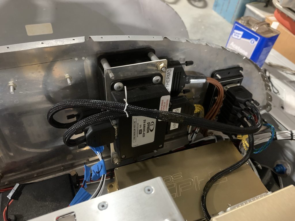
Eventually I just decided to shorten up one of the cables; conveniently, by switching the shorter cable to the further-away ADAHARS, the length was just right, so all I had to do was take about six inches off the other cable and re-terminate it. Further forward, by securing the network cables to the other wiring bundle going aft for a short distance forward of the bulkhead, the portion going across in midair is kept fairly rigid and can’t really flop around (another concern I spent a lot of chin-scratching time worrying about).
Eventually, after a whole lot more cable lacing, I had some nice bundles. Everything ended up nice and tidy:

For routing the bundles forward to the rear seat armrests, I used some of my adhesive zip-tie pads. I think I’ve finally figure out how to make these work – instead of peeling off the foam adhesive they come with in favor of the supposedly better VHB tape, I’m just using the foam adhesive. I’ve placed several of these pads now and they seem to be holding well.
Anyway, for the time being I’ve just secured the bundles to the pads with twist-ties; when they’re secure finally I’ll wrap the bundles in silicone tape for extra protection. But we can still get a look at the routing on the left side (these are for the flap motor and seat heat control):

And on the right side, where we have the headset and charge port wires going forward, and the tail branch going aft:

Further back, the bundle including the network cables need to route from the lower bulkhead penetration to a higher one. This means it has to go across a longeron, which in turn means we need more securing, to keep the bundle stable and off the edge of the longeron to avoid chafing. In this spot, I mounted an adel clamp to the longeron and also wrapped the area in silicone tape just in case this bundle happens to wiggle and make light contact with the longeron:

Finally, I disconnected everything on the rear shelf and removed it, so I could drill the adel clamp mount holes to final size and install nutplates. With the clamps installed with actual screws instead of clecos, I could temporarily put the baggage well in place and see how everything lined up. A top-down view shows that I’ve got nice clearance between the harness bundle and the aft part of the well. The bundles going forward also have plenty of clearance around the corners:

The other thing I got done today was to install that pesky resistor for the transponder’s serial input from the GPS-175. I ended up removing the lacing about halfway across the front of the shelf, just so I could add the resistor somewhere where it’d be secured in a larger bundle to help avoid any failure down the road. If you look really carefully you might even see it in the previous photo.
So, what next? I’m not sure if I want to work in the rear armrest terminations (installing the headset jacks, charge port, etc), or leave those alone and move back forward to the panel. Well, there’s also finishing up some of the stuff under the seats as well – some of that is pretty clear-cut (the wing connections and flap controller), but for the rear stick connection, I think I may want the control column installed. And I kind of want to go ahead and install the transponder/ADS-B antennas and get the coax runs for those done.
A larger question I need to think of is whether I intend to use the fuselage rotisserie any more. That comes into play as I decide how to handle the two tail connections – I’ll want the empennage mounted again to finalize those, and once the empennage is back on the rotisserie function becomes unusable. And I might want the rotisserie stuff off the firewall anyway so I can get the ground bus mounted and all those wires terminated. Basically, I’m somewhat loathe to remove it but I’m starting to think I’m pretty much done with rotisserie type stuff.
So yeah…plenty to think about, I suppose.