Electrical

More assorted aft wiring stuff

Well, at least there were no tornados tonight, that’s something. Anyway, I figured I’d pick back up with the aft shelf wiring, working towards the couple of remaining terminations (the transponder and network cable). Both of these branches are pretty obviously longer than they need to be, so the first order of business here is to finalize the actual routing so I can figure out how much trimming I need to do on those branches.

So I started with lacing the harness where it comes out of the conduit, intending to work from there. I got as far as where the harness needs to split and then got hung up a bit thinking about the rest:

 I don’t really like how this is tending to put tension on the ELT plug, so I think I want to add something here to secure the bundle a little further left to relieve that tension. I think I’m going to use an adhesive pad with a zip tie here, but not 100% sure yet. Instead I got to thinking about how the rest of the routing would go here, which also includes the power/ground/disconnect branch to the autopilot pitch servo. I decided that to really finalize the routing here, I should get the servo temporarily installed as well, so I took a break from working back here to work on the servos.

I’ve had both servos on hand for a while now, but neither have any kind of connector. The servos use a modified Skyview network connector – they retain the two data pairs, but instead of the two power/ground pairs and an aux line, there’s just a single power/ground pair and the disconnect line. An important point here is that mixing up normal network connectors with an autopilot connector could cause damage to other components; presumably the direct power feed from the bus is higher voltage/current than the network feeds.

Anyway, the takeaway from this is that I wanted to be careful about these connectors to avoid the possibility of making this mistake. What I decided a while back was that the pitch servo will have a DB9 connector and plug into the network hub, but that connector will only house the data pairs. The other three wires will be separated, and be connected to the harness with simple D-sub pins and sockets, secured with heat shrink.

A nice consequence of this is that it sets a standard that prevents mix-ups later. In order to plug into the network hub, the connector needs to be female. And since I want both servos terminated the same way, that means the roll servo – which will have all wires in a single connector for simplicity – will also have a female connector. That, in turn, means that the servo cable that will run out the right wing will be impossible to accidentally connect to a regular network device.

That’s a big long intro for just saying that I proceeded to sit down with both servos and finish out their harnesses. Below you can see the roll servo on the right, and the pitch servo on the left (with the separated non-data pigtail):

And finally, I temporarily installed the pitch servo to get ready for handling routing concerns:

So maybe tomorrow I can actually get to terminating the network and transponder branches. I think that’s the next logical step, followed by working out securing and routing the other branches from this area.

Posted in Avionics, Electrical, Fuselage | Hours Logged: 2

Last aft shelf terminations

More stuff to terminate tonight, but before I could get to that I needed work work out some of the routing issues back here. I ended up adding a few adel clamps attached to the forward lip of the shelf, starting with one to secure the branch towards the ELT. This was the critical point, as I wanted to make sure I didn’t have tension on the ELT and ADS-B connectors. For now, the adel clamp is just clecoed into place; later on I’ll add nutplatesfor permanent installation.

Getting the secured let me start lacing up the branch across the front of the shelf, towards the left side, which in turn let me finalize the branches to the transponder and network hub. I added another adel clamp just before the branch to the the network hub, and one more just past the transponder. That last one is necessary to make sure the branch going forward for the flaps and seat heat control will lay against the fuselage skin and not rub against the backside of the baggage well.

So now it’s starting to really look organized back here:

There was one unexpected development tonight. As I was finishing up the transponder connector, I needed a backshell. Apparently I didn’t have one of these on hand, but that’s OK, because the transponder came with a connector kit. I just needed to go root through the box it came in to find it. What caught me off guard was seeing that there was a small resistor included in the connector kit. That was immediately concerning to me because I had no idea what its purpose was, and that was a knowledge gap I needed to stop and resolve immediately.

Turns out that, for whatever reason, if you’re using an external GPS to input position data for ADS-B compliance (which I am, using the TSO’d GPS-175), you’re supposed to wire this resistor inline with that serial data line. I have no idea why this is, seems to me it ought to work like any other serial data line, but apparently not.

The immediate next question was whether I should stop assembling the connector and add the resistor at that point. I eventually decided against that; the most immediate reason was that I didn’t want to put it in the short pigtail from the harness trunk to the connector. I’ll want those solder joints to be somewhere they’re well-secured against any repetitive motion or strain. At the moment I’m thinking that I’ll either add the resistor a bit upstream in the harness trunk, or else install it at the GPS-175 connector.

Anyway, this mostly completed the wiring in the aft shelf area. I still need to finish up bundling, routing, and securing the branches that leave this area, in addition to reinstalling the two network cables from the hub back to the ADAHRS units. That last part may entail re-lacing the lateral trunk I did tonight, assuming I decide I want those two cables to be permanently secured to the trunk. That decision will hinge a bit on how I can route them, specifically as it relates to ensuring I can remove this shelf down the road if needed for service.

Posted in Avionics, Electrical, Fuselage | Hours Logged: 2.5

Cable management in the tail

Today was pretty much just lots and lots of bundling and routing things. About the biggest thing I needed to figure out was how exactly I wanted to route the two network cables from the hub back to the ADAHRS units. I dabbed up those two cables some time ago, when I was working on the ADAHRS mount – for some reason I guess I just really wanted to do some wiring stuff. At the time I figured I was making them a good length for the routing, but what I ended up with were cables that were almost the worst possible length.

Most of this boils down to how the cables should be routed around the aft shelf. They pass through the bulkhead above the shelf, and then need to go down and across to get to the hub. The two routing choices here are either to bundle them with the trunk across the front of the shelf, or take a more direct route separate for the trunk. Problem is, the cables are way too short for the former, but kind of too long for the latter. Pulling out slack to the rear just gave me a different problem of managing the cables further back.

Eventually I just decided to shorten up one of the cables; conveniently, by switching the shorter cable to the further-away ADAHARS, the length was just right, so all I had to do was take about six inches off the other cable and re-terminate it. Further forward, by securing the network cables to the other wiring bundle going aft for a short distance forward of the bulkhead, the portion going across in midair is kept fairly rigid and can’t really flop around (another concern I spent a lot of chin-scratching time worrying about).

Eventually, after a whole lot more cable lacing, I had some nice bundles. Everything ended up nice and tidy:

For routing the bundles forward to the rear seat armrests, I used some of my adhesive zip-tie pads. I think I’ve finally figure out how to make these work – instead of peeling off the foam adhesive they come with in favor of the supposedly better VHB tape, I’m just using the foam adhesive. I’ve placed several of these pads now and they seem to be holding well.

Anyway, for the time being I’ve just secured the bundles to the pads with twist-ties; when they’re secure finally I’ll wrap the bundles in silicone tape for extra protection. But we can still get a look at the routing on the left side (these are for the flap motor and seat heat control):

And on the right side, where we have the headset and charge port wires going forward, and the tail branch going aft:

Further back, the bundle including the network cables need to route from the lower bulkhead penetration to a higher one. This means it has to go across a longeron, which in turn means we need more securing, to keep the bundle stable and off the edge of the longeron to avoid chafing. In this spot, I mounted an adel clamp to the longeron and also wrapped the area in silicone tape just in case this bundle happens to wiggle and make light contact with the longeron:

Finally, I disconnected everything on the rear shelf and removed it, so I could drill the adel clamp mount holes to final size and install nutplates. With the clamps installed with actual screws instead of clecos, I could temporarily put the baggage well in place and see how everything lined up. A top-down view shows that I’ve got nice clearance between the harness bundle and the aft part of the well. The bundles going forward also have plenty of clearance around the corners:

The other thing I got done today was to install that pesky resistor for the transponder’s serial input from the GPS-175. I ended up removing the lacing about halfway across the front of the shelf, just so I could add the resistor somewhere where it’d be secured in a larger bundle to help avoid any failure down the road. If you look really carefully you might even see it in the previous photo.

So, what next? I’m not sure if I want to work in the rear armrest terminations (installing the headset jacks, charge port, etc), or leave those alone and move back forward to the panel. Well, there’s also finishing up some of the stuff under the seats as well – some of that is pretty clear-cut (the wing connections and flap controller), but for the rear stick connection, I think I may want the control column installed. And I kind of want to go ahead and install the transponder/ADS-B antennas and get the coax runs for those done.

A larger question I need to think of is whether I intend to use the fuselage rotisserie any more. That comes into play as I decide how to handle the two tail connections – I’ll want the empennage mounted again to finalize those, and once the empennage is back on the rotisserie function becomes unusable. And I might want the rotisserie stuff off the firewall anyway so I can get the ground bus mounted and all those wires terminated. Basically, I’m somewhat loathe to remove it but I’m starting to think I’m pretty much done with rotisserie type stuff.

So yeah…plenty to think about, I suppose.

Posted in Avionics, Electrical, Fuselage | Hours Logged: 5

Panel network cables

The main challenge for today was deciding what to work on next. In the end, I decided that after lots of days hunching over the fuselage making things look nice, I wanted something a little simpler and brain-dead to work on…like making some network cables. So I pulled the center panel section out of the fuselage and put it on the table where I could work on it in a nice sitting position, then got to work.

Things got off to a sort of slow start. The first cable I made, I was so intent on making it nice and tidy that…I forgot to account for the length of the backshells, and so that cable became garbage. It was a good learning experience, though, after that I had a pretty solid formula for figuring out the cable lengths.

One thing’s for sure, by the time I was done today I was pretty much pinning these things up in my sleep, without even having to refer to the pinout in the documentation. Of course, I still tested each cable to make sure they were correct before installing them…last thing I need is to get overconfident and fry some expensive electronics.

In the end, I made five cables today; four of them for the center panel, and one other one (more on that another day, when I finish its siblings). All the components here have two network ports, which allows for nice convenient daisy-chaining, so I’ve got cables working sort of across the panel. The intent is for these cables to come out with the center panel for service, which is why they’re routed completely separately from the other harness.

Anyway, that’s enough talking, let’s get a photo in here:

So that just leaves me with two more network cables to make, which will finish off all the network runs, with the exception of the modified one out to the AP roll servo out in the right wing. Very conveniently, I have almost the exact amount of 22ga black wire left that I need to make those last two cables…I was a little concerned I was going to come up short. I’ll still need more to get that roll servo run down, but that’s a ways down the road, so no hurry.

I think the real critical task right now is figuring out how to secure the harness trunk inside the right gear tower. I’d like to get the thing fixed in place in there before I start worrying about the other terminations in the panel area. I need to double check, but I’m pretty sure I need larger adel clamps to get that done, or I probably would have done it already…

Posted in Avionics, Electrical, Fuselage | Hours Logged: 4.5

Finishing up network cables

Yup…that’s it, I’m done with network cables. Well, sort of…more on that in a bit. Tonight was just making those last two cables, which went pretty much with no additional explanation needed. These two plus the last one from yesterday gave me the three cables from the forward hub to the ARINC and EMS boxes, along with the Skyview MFD (thus beginning the daisy chain seen yesterday).

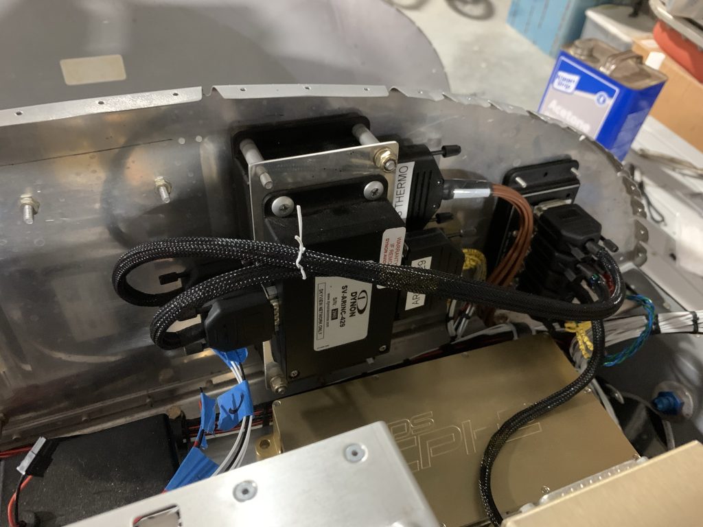
The two cables to the ARINC and EMS are nice and tidy, but I may end up lacing them together…or else figure out some way to secure them in place here. Maybe a cable loop on one of those mount screws? For now, a good old zip tie makes them tuck together decently:

Also visible in the lower right of that photo is the cable going to the Skyview display. Here’s another view of that one:

This brings me to the “well sort of” part of being done. The one thing I forgot to account for when measuring for this last cable was the nice big service loop in the rest of the center panel harness. The idea is that I can remove the panel, bring it back into my lap, and then disconnect all the plugs. The main service loop is plenty long for that, but there’s only maybe a few inches of extra in this network cable.

The contrast is abundantly clear in this photo, showing the large main service loop compared to that little jog in the network cable:

I’m going to leave it as-is for now – among other things, I don’t have any more 22AWG black wire with which to make another cable – and at some point test to see how annoying it is when removing the panel. I expect I’ll probably end up making a longer replacement cable at some point, though…I’m pretty sure that as-is it’ll be somewhere between extremely annoying and impossible to remove the panel with this thing in there. Oh well, can’t win ‘em all.

Final order of business for the night was to get all these connectors labeled. Since these are all bespoke cables for their runs, I don’t want to be at some point in the future where I have to trial-and-error all of these until I figure out which one goes where. Besides, I wanted to remind the label maker that it could print something other than miles of heat shrink tubing:

So that’s a good night’s work. I suppose my next order of business is to start working on more terminations behind the panel. I want to shorten and route the harness from the CPI backup battery to the ignition box, and then get the terminations done for the voltage regulators…though this brings me back to figuring out how to secure that main trunk in the gear tower first. Guess I’m going to have to go ahead and cross that bridge.

I also ordered another pile of stuff from Digi-key today, Some of that stuff will be required to finish these terminations, though I’ve still got materials to get started on the switch connections and so forth. Hopefully that order will come in by the end of the week.

Posted in Avionics, Electrical, Fuselage | Hours Logged: 1.5

Some more harness routing

Today I started out with a specific goal: finally solving the problem of securing the harness bundle coming up the right gear tower. After a whole bunch of staring, I decided the way to go was to mount an adel clap to the forward gear tower brace. I was kind of surprised to discover there was already a prepunched #8 hole pretty close to where I needed it, which made it a little simple to figure out that positioning. I added a nutplate to the spot, so I could just install a screw to secure the adel clamp.

This didn’t quite go off without a hitch, though. When I drilled the screw hole to final size, it didn’t seem like the air drill was running at full speed. Then when I went to go swap to a #40 bit for the nutplate rivets…I heard buzzing from inside the drill. Turns out a mud dauber got in there somehow, and was apparently stranded; even after removing the quick-disconnect air fitting and banging the drill on a hard surface, it wouldn’t come out. So I ended up disassembling the drill to get the stupid thing out.

Anyway, I digress…Installing that nutplate required me to remove the instrument panel surround as well as the upper avionics shelf. While I had the shelf off, I decided it was a good time to go ahead and take care of the harness between the CPI2 backup battery and the main ECU unit. The prefab harness was a good foot or so longer than I needed, so I elected to cut it down and re-terminate it with new Molex pins. Some cable lacing on the harness, plus a few zip-tie mount pads, made for a nice tidy end result:

So now the shelf is back in the fuselage with the harness rerouted…I think next up should be the terminations for the voltage regulators, along with maybe going ahead and terminating the pigtails for the GPS antenna and avionics fan. I also want to shorten and re-terminate the roll servo connection at the forward network hub – there’s a lot of excess wire length there that’s just untidy. Then I guess I get to think about the CPI2 and assorted panel mount switches.

Posted in Avionics, Electrical, Fuselage | Hours Logged: 3

Voltage regulator connections

Just chipping away a bit more today. I ended up revisiting some of the network cables from last week – I noticed the braided wrap around them (which I tried to pull somewhat snug) wasn’t being held by the heat shrink at the D-sub back shells and starting to pull out, so I added some silicone tape for extra security. I think if I make any more of these, I need to 1) cut the wrap a bit longer and 2) use a longer piece of heat shrink. Or maybe just preemptively wrap with tape, I dunno.

Anyway, next I moved over to the fuselage to work on the voltage regulators. These just use ring terminals for the connections, which sort of simplifies the work here but also means it’s easier to mis-connect things (both today and later on if I service anything). I took the extra time here to trim each wire individually to not only make things look nice and tidy, but also make it more evident which wire goes where. Still, it’s a little non obvious, so I’m also thinking of adding labels on the regulators themselves to show which terminal is for what…otherwise any time these get removed and reconnected it’ll require referencing the documentation.

It does look tidy now though:

I attempted to go back out and work a bit more after dinner, but the mosquitos are pretty bad here after the last couple weeks of rain – especially if it’s after dark and you’re inside a brightly lit hangar with the doors open. And it’s a bit too warm to just shut the doors, so…we’ll pick back up tomorrow.

Posted in Avionics, Electrical, Fuselage | Hours Logged: 2.5

Switches!

Well, not an especially productive day, but I did get a few things done. I added a Molex connector for the CO detector unit on the baggage bulkhead, and then did all the terminations for the left panel wing. This includes the three switches over there along with the panel light dimmer:

I also started looking at the switches on the right wing, which need to tie into the CPI2 ECU. Figuring out how to route everything will be a bit more interesting over there, compared to the pretty simple wiring runs on the left. Among other things, I need to figure out which coil kill lead goes to which switch. On the one hand, it doesn’t really matter, since the idea is to just be able to disable them one at a time for preflight checks, but on the other hand, if one of those checks fails, it’d be nice to know reliably which coil pack is the problem.

Posted in Avionics, Electrical, Fuselage | Hours Logged: 1.5

CPI wiring

Well, I made it a whole hour. Turns out that when there’s a significant mosquito population, waiting until after dark and working in a brightly-lit hangar is maybe not the best choice. Oh well, I still got things done.

The handful of preinstalled wires for the CPI ECU are done – these were just the four ground wires and two tach wires to the EMS. I went ahead and installed the power wires into the connectors as well, but didn’t get to the next point with those, which will be terminating them at the two panel switches. Then I’ll just need to add the kill switch wires and this will be done…well aside from the harnesses that need to be fed in through the firewall from the engine compartment.

In any case, here’s the harness as it stands tonight:

Posted in Avionics, Electrical, Fuselage | Hours Logged: 1

CPI wiring complete (for now)

Again, nothing to really go in-depth about tonight. I got the two ignition control switches wired up, with the power/ground feeds from the main harness and the switched power and kill leads to the ECU. There was a little bit of thinking here about how to orient everything, but nothing too crazy. In the end I’ll probably zip-tie the two switch plugs together just to help stabilize them a bit and decrease any stress on the connections.

I also decided to take care of the ELT switch while I was over here. This ended up being one spot where I didn’t make the wires quite long enough, so I ended up doing a solder splice on each wire to give them an extra few inches to reach the switch without stretching. So now all this stuff on the right panel wing is wired up:

The wires over to the CPI ECU need to be bundled up so they can be all nice and neat, but since I still have the coil and crank trigger harnesses to fish into here, there’s not much point doing so. So for the moment they’ll just look kind of disorganized:

What’s next? Well, I guess maybe I’ll see about the switch console…getting all those wires trimmed, terminated, and pinned up should be fun, since there won’t be a ton of space…but it’s got to get done.

Posted in Avionics, Electrical, Fuselage | Hours Logged: 2