Panel harness layout, again

It’s kind of challenging sometimes to keep a positive attitude right now. Even though I’m rationally aware that the stuff I’m doing is progress, emotionally it doesn’t seem super productive spending time standing around staring at things, grunting sporadically, and maybe sketching on a whiteboard from time to time. And that’s pretty much how I spent today, just really try to think about how to best route all the wiring runs behind the panel. Along the way, I changed my mind about some stuff…again. Sometimes I’m never quite sure if I’m being indecisive here and going in circles questioning myself, or actually refining things over time. I’m pretty sure it’s the latter, but the human brain sure is a pesky thing sometimes.

Anyway, the one big decision I made was about how to route the wiring runs going forward of the firewall. I’ve always been planning to bring the main power supply cables in through the left side of the aircraft, through a prepunched hole, but then there’s all the sensor connections and so forth. My working plan had been to route this bundle just inside the deep part of the forward baggage compartment – this would keep the wires from being exposed to potential damage in there.

But the more I considered the logistics of this, the less sense it made. Most notably, trying to work out the harness junction over by the right gear tower would be challenging, but also, I’d have to figure out how to get that bundle to turn a really tight corner to head for the firewall, which would mean also getting liberal with adel clamps or something to secure the bundle. The real kicker, though, was this – keeping the wires out of the baggage area to avoid damage seems good, but instead putting it right beside where my feet will go every single time I fly maybe isn’t such an improvement.

Now, there is a stiffener riveted to the side skin about halfway up from the floor, but it doesn’t stick out too far. Still seemed like this was a potential spot to route the bundle, and keep it protected and somewhat out of sight. Question was…how big would this bundle be? Kind of an important consideration. So I gathered up some of the preexisting harness pieces that would make up this bundle – the eight thermocouple wire pairs and the CPI2 bundles for the coil packs and crank trigger sensors. The only thing missing was for the other engine sensors…OK, time to go refer to my schematics. Turns out this is simpler than it seems, and all those sensors only require eight more wires. This was starting to seem manageable.

Finally, I checked the harness pieces I had against a snap bushing, and found one that they went through with plenty of room for a few more wires. Overall it looks like the bundle will be 1/2” to 3/4” in diameter. Very manageable for this spot. Really, the only thing to work out is how to secure the bundle. There are a couple of options here, but so far I’m leaning towards adding another piece of angle to create a protected space for the bundle…or I might just put some of my ample conduit supply here, just not sure the best way to secure it.

That can wait, because even if I don’t know the exact solution I’ll go with, I’m sure it’s a solvable problem, and all this head-scratching was just in service of figuring out where the harness would split back by the gear tower. Between this decision and a few other similar (but less complex) machinations, I finally got to a point where I felt comfortable expanding on my harness diagram, to cover the entire area behind the panel:

This lays out the general architecture back there: the harness will split somewhere near the right side of the upper shelf, with one bundle serving the components on the shelf, baggage bulkhead, and panel wings (the righthand branch), and another serving the removable center panel. That latter will need some kind of allowance for a service loop, so I can pull the center panel out and disconnect everything for, well, service. Of course, even as I write this, I realize that I forgot a few components here, but nothing that majorly changes things.

The one conclusion I’m coming to here is that it’s probably high time I stopped trying to envision the entire harness in my head, and started actually stringing wires and solving problems in the real world. Which means that I absolutely need to get off my butt and finish the fuselage riveting that I’ve been putting off for so long. Once that’s done, what I think I’ll do for the harness is build up the portions between the tail of the aircraft and the top of the right gear tower, and pull that through the fuselage. For the rest, including all the behind-the-panel and firewall-forward portions, I think I’ll be better off building the harnesses in place, rather than trying to carefully measure each one of those branches above and prepare harnesses on a table.

In the meantime, I can still go ahead and get components mounted to the shelves and baggage bulkhead, in addition to doing the cutting on the wings. But I still feel like I’ve got to stop putting off the riveting work. That’s sort of the elephant in the room that’s roadblocking real progress.

Posted in Avionics, Electrical, Fuselage | Hours Logged: 3

Panel harness layout work

So tonight was about starting to figure out what the harness behind the panel ought to look like. It started with sitting inside and looking over my schematics, with the main goal being to decide whether to not I wanted to add in disconnects for certain modules (like the center panel or the upper shelf). After doing a bit of thinking and tallying up pins that would be needed, I decided that adding those disconnects wasn’t worth the effort. I think the main benefit of doing a single disconnect would be simplifying the service loop needed to allow removing the panel, but at the cost of more planning, more parts to order, and more wire terminations that could be a source of issues down the road.

With that decision made, it was time to start making a go at the layout. I decide to try and do some sort of iterative whiteboard work, sketching out the layout and visualizing the interconnects between devices. The idea is just to layout the paths that wire bundles will have to take, not to detail every single wire. The end result I’m going for is a diagram like the one I drew a while back for the harness to the tail of the aircraft – basically just laying out the wire runs and nodes, which I can then turn into measurements that become the baseline for harness building.

This, in turn, made me rethink some of my wire routing decisions. Initially I’d expect to have significant wire bundles exiting the upper shelf on both the left and right – on the right side would be power/ground connections, plus the beginnings of the run to the aft fuselage, and on the left would be the firewall forward runs, for the engine management system. The main hangup with the latter is that I intend to run the CPI2 FWF harnesses just inside the forward baggage well, to keep the wiring runs manageable. I think it makes more sense to run all the FWF EMS runs through that point, rather than splitting them up. That will leave me with just two firewall penetrations for wiring – the CPI/EMS one we’re talking about here, and one on the far left where the main power feed from the battery will enter.

I think this will be good for packaging behind the panel as well. On the left side I’ll have some SCAT tubing to feed the fresh air vent, which would potentially make routing a decent size wire bundle more interesting. By taking the bulk of the wiring off the left side, this makes things a little simpler. There will still be some wiring over here, but it’ll be limited to a pair of coax runs (for the radio and GPS antennas) and a few wires for fuel pump power and the left tank level sender.

Anyway, the end result of this was some fairly indistinct whiteboard material. Probably this entire diagram will go away and I’ll start over again, because while it decently depicts the interconnects between boxes, I don’t think it’s going to work for depicting the actual harness layout. I expect to end up with sort of two horizontal “trunks” – one that represents connections being router from the far right across assorted boxes, and another that links all the main panel stuff (and this can include the aforementioned service loop).

So at a glance it kind of seems like wasted work, but I think it did wonders for helping me get a better rental image of how things will go together here. I’ve just gotta do a lot more drawing…

Posted in Avionics, Electrical, Fuselage | Hours Logged: 1.5

Behind-the-panel planning

As mentioned yesterday, with the main panel layout done, today I started thinking (again) about the layout of the stuff behind the panel. Also as mentioned yesterday, I wasn’t quite totally on board with the working layout I had after looking at all the actual components in place. So I started the day off just sort of staring and occasionally moving stuff around. I also got to thinking more about actual wire routing considerations, specifically the way the various D-sub connectors might affect things. To this end, I actually spent some time assembling a bunch of connectors and backshells so I could better visualize things.

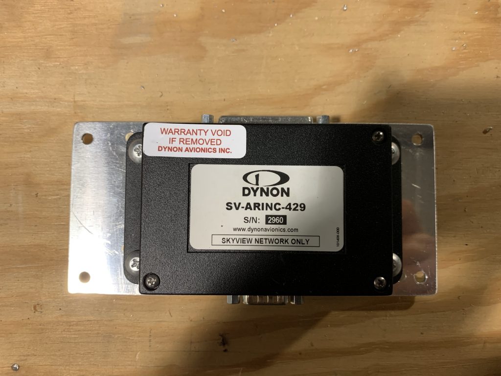
In the end, even after moving stuff around, I was still dissatisfied. Everything seemed more cramped than I wanted it, especially the components on the baggage bulkhead. After lots more staring, I got to thinking about an idea I had a while back and, at the time, rejected – specifically, instead of placing the EMS and ARINC-429 boxes side-by side, figuring out a way to stack them. The thing with both of these boxes is that they have D-sub connectors on two sides, which means they needed decent real estate on either side for those harnesses. If I could stack them, that’d be less dead space I’d have to leave.

Now, there were two reasons I’d rejected this idea previously. First, I was concerned about the extra height of the stacked units – but that was several shelf iterations ago, and now I felt that was less of an issue. Second, I couldn’t visualize any stacking ideas that didn’t seem really unpleasant to deal with – most of them revolved around making a pair of z-profile brackets, and it seemed like a really fiddly thing to deal with behind the panel down the road. But today I had a better idea – thanks to cutting the panel (twice), I’ve got some scrap pieces of thick sheet lying around. Maybe I could fabricate something like the plate Dynon sells for stacking two ADAHRS units.

In the end, I decided to have a go at fabricating a mount, knowing that it might be wasted work if the packaging still didn’t work out. The idea was to cut a plate matching the base of the larger EMS unit, which would be mounted using the same stud mount I plan on the EMS unit, using spacers or standoffs to position ti above the EMS unit. Then I could just install nutplates on the mount plate, and screw the ARINC unit to it. Pretty straightforward work, really.

Cutting the plate was easy, as was getting the mount holes drilled for both the EMS and ARINC units. To help with potential interference with other stuff on the shelf, I positioned the ARINC unit off to one side (which, when mounted, means “higher up”) rather than centering it – this would provide more space near the shelf. Then I got my nutplates fitted and installed, and screwed the ARINC unit to the plate:

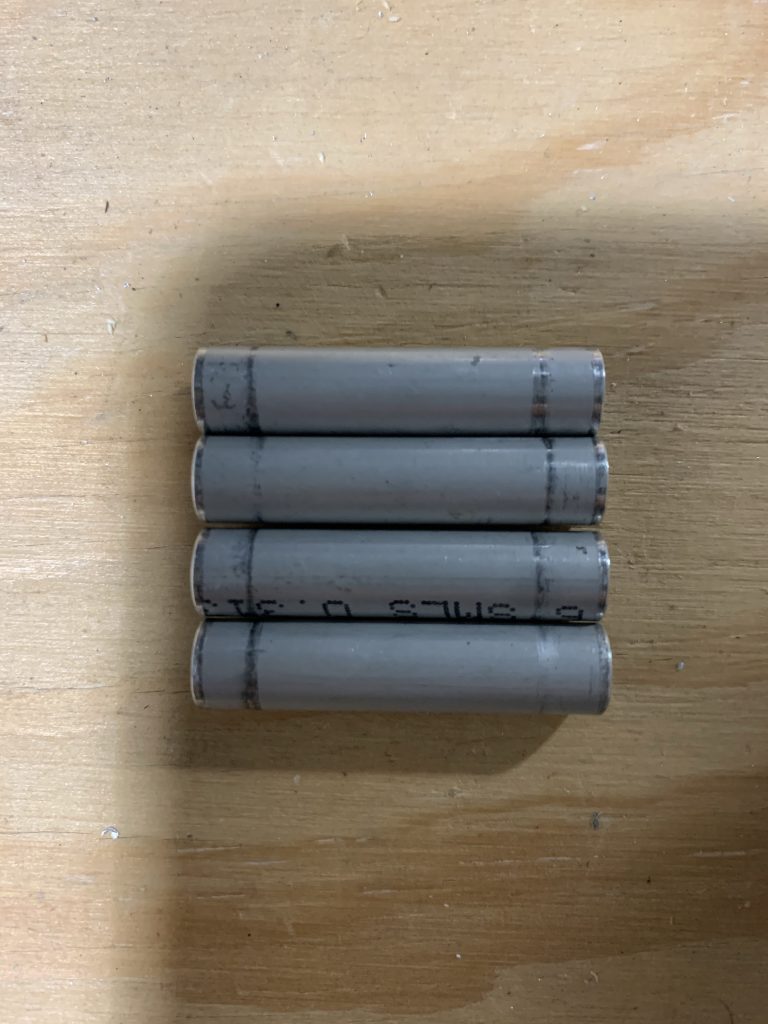
Next up were the standoffs. The mounting holes here are 3/16”, which makes this easy – I’ve got a bunch of aluminum tube that gets used for spacers on AN3 bolts like this all over the place. I even had a convenient donor piece: my first failed attempt at making the aileron trim pushrod. I worked out that the spacers needed to be 1 3/8” long to provide some space between the ARIND mount nutplates and the EMS unit, then did some cutting and finishing. And here we are, four nice little spacers:

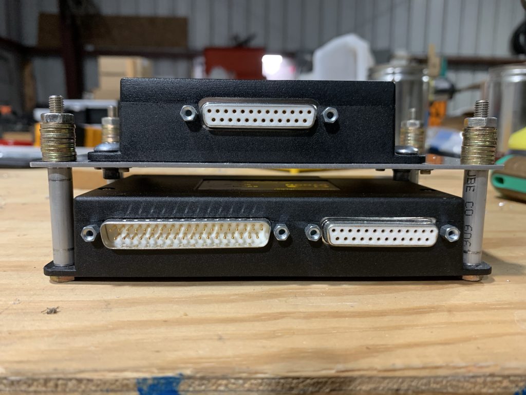
Finally, it was time to put it all together! Only one problem: I didn’t have the right length of machine screws, since when I made my hardware order I wasn’t thinking of this application. But hey, I don’t need the actual hardware, I just need something to hold the assembly together so I can test-fit. I eventually found some AN3 bolts that would do the job, although they were way too long, thus requiring an absurd number of washers. Oh well, it gets the job done:

And so finally, it was time to go back and do the actual test-fitting…and hey, it works! I’d already decided earlier to move the CPI2 ECU over to the far right, mainly to provide better access to the fuses if needed. And that provides good room both fore-aft and up-down for the stacked units. It also lets me shift the voltage regulators back towards the center, which I like a little better…and maybe best of all, I can put the Skyview network hub over far right. That should make for some nice routing, since it’s 1) right beside the EMS and ARINC units, each of which have an SVN connection, and 2) convenient to the right HDX display, which is where I’ll start daisy-chaining the assorted panel units together, and 3) convenient to where the wire bundle going to the aft fuselage will exit the panel, which is good because I’ll have two SVN cables going that way from the hub (one for the roll servo, the other to tie into another network hub at the aft shelf).

I also rotated the CPI2 battery mount so its fuses face inboard as well, again for potential serviceability. The sole wrinkle here is that the Skyview backup batteries end up right between the ECU and battery for the CPI2 – this may make it tough to pull any of those fuses. But if that’s the case, I’ll always be able to remove the Skyview batteries if I need to – it’ll just be two plugs and four screws. Given that I don’t expect to be changing those fuses often, I think that’s acceptable.

This arrangement should also work well for potential servicing. The first step to working back here would be pulling the center panel unit – 12 mount screws to detach it, followed by seven plugs (one plug each for the two HDX displays, the GPS-175, the intercom, the radio head, and the AP panel, plus the SVN connector from the right-hand HDX display). I may consider trying to consolidate this into something like one or two cannon plugs or something, just for simplicity – I think that’ll depend on how all the harnesses end up tying together.

Anyway, back to servicing…with the center panel out, the entire upper shelf will also be removable, with about the same number of connectors: the two Skyview backup batteries, the D-sub and coax connector to the radio box, and the CPI2 connectors. The same thing applies here about maybe adding cannon plugs – that might be worthwhile to make this a little easier. I think the packaging for that might be more challenging, though.

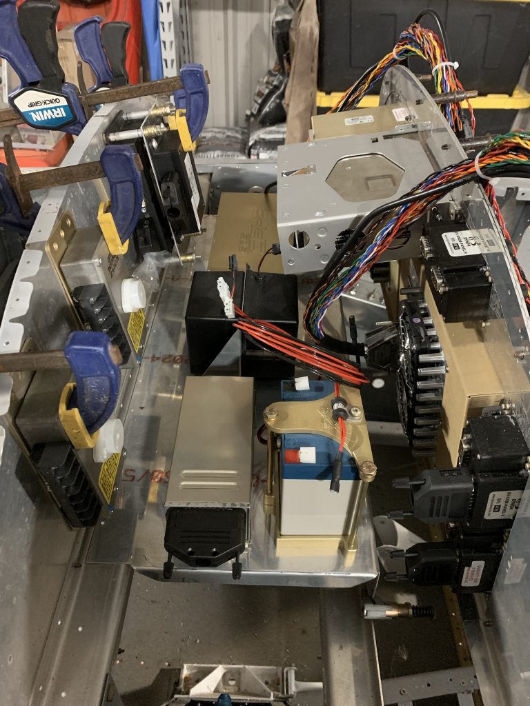
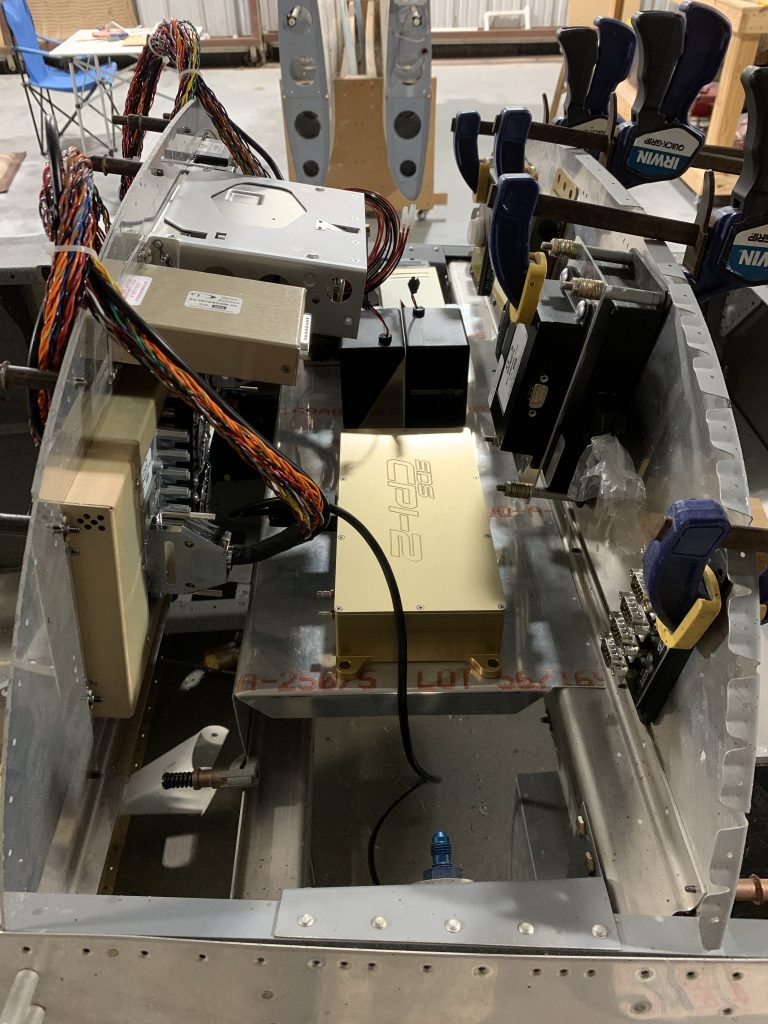
Anyway, let’s get to some photos. First is a look at the area from the left side of the aircraft. On the baggage bulkhead, we have the two regulators closest, followed by the EMS/ARINC stack – with plenty of space for those connectors. On the shelf, we’ve got the radio box, CPI2 battery, Skyview batteries, and finally the CPI2 ECU:

And from the left side…the only thing to note here is the SVN hub, which wasn’t visible from the other side. You can also see a black cable coming from the CPI2 ECU and sort of just going down by the gear tower. This is the cable that will tie into the CPI2 panel controller, which will be on the right wing of the panel.

So there we have it – not a lot of progress in terms of tangible stuff today, but I’m starting to develop a solid mental picture of how everything up here is going to tie together. I really think the next steps here will be to get the panel wings cut and drilled for their components, so I can mock things up a bit more. I’ve also got probably another Spruce order to work up – I need the longer machine screws for the stacked EMS/ARINC mount, plus also maybe some hardware for mounting the CPI2 ECU.

There’s also one more component to add, a pretty late addition – I didn’t even think about having a carbon monoxide detector until this past week. These are pretty ubiquitous in piston aircraft, and most often are just these cheesy little cardboard things taped to the panel. The accuracy of those seems to be questioned, they have to be replaced periodically, it takes up space on the panel, and it relies on me noticing a color change.

This is, of course, all a setup for something better I found – an electronic CO detector, which can mount behind the panel, and is compatible with the Skyview EMS unit. What this means is that 1) I don’t have to take up panel space and 2) instead of having to watch for a color change, I can assign audible alarms via the EMS system – so if there’s ever a CO problem, I’ll get yelled at in the headset the moment it crosses a set threshold. The good news is, the detector unit is really small, just 2” square – easy to fit in back here.

So I think I’ve got the mission(s) for the week: more panel cutting, working up that hardware order, and firming up the harness layout behind the panel. Nice to have a solid path forward.

Posted in Avionics, Electrical, Fuselage | Hours Logged: 3.5

Finished cutting main panel

So ends a few weeks of “vacation,” so to speak. Not sure why I got back in my “do other stuff but not airplane building” habit, but it happened. But hey, here we are again.

The one fun thing I had to figure out how to deal with was the Dynon intercom. The main issue at hand was that the mount holes in the faceplate were, for some reason, larger than the other three similarly-sized units. Everything else mounts with #6 screws, but the intercom had holes for #8 screws. That seemed wrong, but it turns out that it’s intentional, or so I was told by the Dynon folks. Their advice was to use mount it with #6 screws anyway.

Well, that could work, but there’s another issue with the intercom: the panel cutout specified in the manual was much larger than the actual unit. That, in turn, would mean that the screws would have to do all the work of locating the intercom, which would in turn be problematic since they’d be undersize. I was just imagining having to carefully align the intercom while tightening the screws every time it had to come out. This isn’t an issue with the other units because the panel cutouts are a snug fit – the unit is primarily located by the cutout, and the screw just secure it to the panel.

After thinking this over quite a bit, I decided to fab up a piece of sheet with a cutout sized to snugly fit the intercom; this could be riveted to the panel itself, with he rivet heads hidden, and thus set this setup like the other units, where the screws weren’t responsible for locating the unit.

It actually took me two tries to make up this plate – I decided to use some scrap .025# sheet, and at first I convinced myself I could make the rough cutout using snips. That turned out to now work out at all; on the second one, I did the rough cut with a Dremel cutoff wheel. Then, just like the rest of the panel, I did lots and lots of filing to size.

Originally I’d expected to not the plate to fit around the nutplates and rivet it separately, but it occurred to me that it’d be simpler to just sandwich it between the panel and the nutplates, and let those rivets also mount it. Getting everything lined up to drill required some brain power, but I got it done. (though not without drilling some shallow holes in the back of the intercom faceplate…oops)

Here’s a look at the locator plate riveted in place with the nutplates. It looks kind of crappy, mainly because the larger cutout in the panel never got really squared up since it was already oversize. None of this is visible with stuff installed, thankfully.

Then it was on to the GPS-175 rack. This was another bit that required some thinking to figure out the fitting process – I ended up removing the knob panel and intercom so I could clamp it in place using the mounting angles. Took a fair bit of trial and error to get things straight before I finally felt comfortable drilling the holes to rivet the angles to the panel. I was acutely aware that a mistake here would probably mean starting over…again. I really didn’t want that.

But it worked out nicely, and then of course I had to get everything installed and hang the thing in the fuselage:

This has me back to the original reason for doing all this: checking the layout behind the panel. I can finally do this for real, because my box from Ross at SDS came in Thursday, so the ECU-shaped piece of cardboard went away and was replaced by the actual ECU unit (visible on the shelf just in front of the two Skyview batteries in the next photo). Also visible here is the CPI2 backup battery, now mounted in its tray from SDS:

I’m still not quite sure I’m 100% OK with this layout. I think it’s mostly OK, but the one thing that’d be annoying with this setup would be if any of the six blade fuses on the end of the SDS ECU blew. They’re visible on the box, on the end facing he camera. It’d be kind of fun to try and pull those without removing the entire box from the shelf. Still…I’m thinking it may be unavoidable. I think the only way to make those easier to access would be to turn the ECU box 90°, so the fused faced the panel. Doing that would require adding a little extension to the shelf, as the box is too long to fit on the shelf that way. I dunno if it’s really worth doing that, but I think tomorrow I’ll futz around with positioning stuff here and see if I find anything I like better.

Once I get this stuff mounted, the real fun will begin – deciding exactly how the wiring will be routed back here.

Also, I’m thinking about going ahead and doing the rest of the panel – the outboard wings. Mostly that’ll be doing a few more switch mounts, but there’s also the air vent on the left side and the cutout for the CPI2 controller on the right – that one will be fun since it’s octagonal…

Posted in Avionics, Fuselage | Hours Logged: 4.5

More avionics planning

Today there was plenty to do around the house, so no real time for a dedicated work session. But I couldn’t resist the temptation to temporarily mount everything possible and then stick the partially-done panel into the fuselage for a look:

And to be honest, there was good reason to do this. The thing that prompted me to get going cutting the panel was the desire to finalize the avionics shelf. I felt I had a pretty good layout, but the one thing I needed to evaluate was how the harnesses coming off the displays and other devices might interfere. And as it turns out, this did surface some issues with my previous layout.

On the far right side, the CPI2 controller isn’t going to be able to go right at the edge of the shelf – the main harness from the display is problematic. Here I’ve got the harness attached to that display to help with the layout – notice how it projects over the edge of the shelf:

So it was time for some more moving things around. I think I’ve arrived at a new workable layout; the main changes are moving the Skyview network hub to the baggage bulkhead, moving the CPI2 controller and backup battery to the left, and placing the Skyview backup batteries far right:


The remaining question mark here is still exactly what the CPI2 battery tray is going to look like. I did get the CPI2 ordered this past week, and Ross said they should be able to get to fabbing the harnesses this week, so that should be on hand maybe the week of Thanksgiving. In the meantime, I should be able to get the GPS-175 tray mounted, and hopefully sort out the Dynon intercom issues. I guess I can also get back to the fuse block tray once my Spruce hardware order comes in in the next day or so.

Posted in Avionics, Fuselage | Hours Logged: .5

Panel do-over: finishing holes and adding hardware

Now that’s a solid day of work. Got out bright and early and got to it, even though it was obnoxiously humid until mid-morning.

First up was the grunt work of finishing out all the rough-cut holes. Just lots and lots of filing and repeatedly fitting components into their assorted holes. But finally, after a few hours, it was all done. At this point I was beginning to think how I could stage things to allow for fitting all the components into the panel. Previously I’d just sat it on a few 2x4s on the table, but that only works with the shallow stuff installed. Both the intercom and GPS-175 are too deep for that to work.

Eventually I decided to work up a sort of fixture to allow for fitting work like this as well as maybe other testing down the line. I just took a couple pieces of scrap 2×4 and drilled in assembly with the panel screw holes, so I could cleco the panel to these pieces. Then I cut the bottoms of those pieces at 15° on the miter saw, and nailed another piece of scrap to each one to provide some support. So now I can stand the panel up on the workbench if needed:

And then it was time to stage all the pieces in their holes to see how it all looked. Note that some of this stuff isn’t quite aligned right here, by virtue of not being actually attached. For the displays and the Dynon units other than the intercom, they fit snugly in their holes and look fine. The GPS won’t really be fixed in place until I attach the rack, and the intercom has an oversize hole, which is why it looks low and a bit crooked here:

Next up, it was time to start attaching things. To do this, I just used the screw holes in the components as drill guides for the panel, then did some assorted grunt work to the get nutplates fitted. These are really fun to work with, as they’re miniature nutplates. Riveting in particular was fun; the rivets sit really close to the screw receptacle.

The other fun thing involve the provided mount screws. For the displays, they’re nice little socket head screws, but the small boxes have these pan head screws that accept a 5/32” Allen wrench. I learned the hard way that it’s extremely easy to round the heads on these things if you’re hamfisted (or unwisely use a drill to install the screws). I ended up ruining no less than three of them over the course of the afternoon. The good news is that Dynon sells extra hardware packets. The bad news is that now I need yet another parts order.

I also noticed something really odd – while the other components have #6 mount holes, the intercom has #8 for some reason. At first I thought this was something I’d overlooked before, but the intercom literature claims that it should have #6 holes just like its brethren. Since I bought this secondhand, I thought maybe some idiot had drilled the holes out, but there’s still virgin paint inside the screw holes.

So I’m pretty confused by this, and also unable to get the intercom mounted, since I don’t have the proper hardware. I think I’ll reach out to Dynon on Monday and see if I can just order a new faceplate for the intercom – they’re designed to be switched out (to allow for horizontal or vertical orientations), so it’d be an easy swap. But yeah, yet another thing to deal with before this is done-is.

Anyway, I ended up getting all the nutplates installed for the displays, the radio, and the AP and knob panels. Next up will be the GPS rack mount, but that’s definitely a job for another day.

I would have concluded this with a photo of everything installed in the panel, but thanks to stripping those screws, I no longer have enough to mount everything. Oh well.

Posted in Avionics, Fuselage | Hours Logged: 9

Panel do-over: rough cutting

Not a ton to write here; last time I got all the cut lines laid out, tonight it was time for another marathon session with the jigsaw. This time I was a little more intentional about where I made my pilot holes to start the jigsaw cuts, but the AP panel cutout (down by the lip at the bottom) still couldn’t be cut out as fully as the rest. Oh well, just gotta make do.

After doing the rough jigsaw cuts, I went to work with the Dremel and a cutting bit to remove some extra material around the corners and so forth; this i just to reduce how much I have to remove with files down the line. I’m pretty much at the point now where I shouldn’t need to remove more than 1/16” of material in most places.

So that’s enough for one weeknight; I should be able to find the time to get one filing done this weekend, and hopefully I can finish out all the holes. With any luck, I’ll have a done-ish panel ready to hang in the plane temporarily by the end of the weekend.

Posted in Avionics, Fuselage | Hours Logged: 2

Instrument panel do-over: layout

New panel blank came in today, so I decided to get right to work on it this evening. First step, like before, was to do the layout of the actual devices and the required cut lines. Adding a slight twist was the need to modify the layout a bit; as mentioned before, I need to provide some empty space to the sides of the GPS-175, instead of putting the two Dynon units right up beside it. I decided to complement that bit of empty space by also separating those two units from the screens below; this will probably be more clear as we get to the work here.

First step is to mark the no-go areas of the blank. The removable panel attaches to two side “wings” with screws; those wings are in turn secured to the fuselage. The wings sort of arch together in the top center area, and the end result is an overlap where I can’t really safely cut any holes. So I just checked the wings into place and traced the edge with a sharpie:


Next up is working out the locations of the top three units; I want them as high as they can go without interfering with the wings, and their position essentially drives everything below. So I start out by marking the lateral extent of these. First up is a centerline, then I line out the outside edges of the GPS-175, followed by the empty space required for the rack mount, and finally the knob panel and intercom units. Before going any further, I laid the actual units in place to sanity-check my marks:

And then the intersection of the outermost marks and the “no-go” zone becomes the upper alignment line for these three things. With that as a baseline, I can then draw in the lower edges of the GPS and Dynon units. Additionally, the bottom edge of the GPS becomes the reference line for the top of the displays and other stuff below.

Here the spacing under the two Dynon units becomes more obvious; they’e spaced out about 1/2” from the edges of the GPS, and then by aligning them with the top of the GPS, I get about 1/4” margin between them and the screens below:

Next up is marking the edges of the two screens, plus the radio and AP panel alongside. I also paused to clean up some of the superfluous Sharpie marks to remove any confusions. This is required a folded paper towel soaked in acetone and a very steady hand:

This finishes up outlining the actual bezels of the units; that i the physical space they’ll take up on the front of the panel. Next up is the real fun, drawing the actual cutouts, using the outlines as a reference. It’s just more of the same as before, lots of careful marking and measuring with a ruler and Sharpie. Once that was all done, I did another cleanup session of superfluous marks. And now it’s all ready to go (side note: it sure is fun trying to take decent photos of a reflective surface):

Next up, I get to repeat the fun exercise of doing rough cutouts, followed by lots and lots of filing and such.

Posted in Avionics, Fuselage | Hours Logged: 2

Service letter done, more planning

Another fairly unexciting day, following an unproductive weekend. I shot the rivets for the tailbone stiffeners for the service letter fix, then decided to look at doing some actual mounting of stuff to the fuse block shelf. So I pulled that shelf out, took it to the bench, and started laying things out again, but this time with the actual wire on hand to at least consider routing for the big power feed.

Before long, I’d decided that I no longer liked my original plan of using cheap plastic clips to secure the wire bundles here, and that I wanted to use legitimate adel clamps instead. Only problem with this is that I don’t have the right size ones on hand. Also, it’d be nice to at least get the interconnects between the fuse blocks and other stuff done, but I don’t have the right terminals on hand for that.

So long story short, looks like it’s time for yet another Spruce order.

But hey, I still did stuff, and tomorrow I should get in my new panel blank, and I can get going on attempt #2 at getting that cut.

Posted in Electrical, Fuselage | Hours Logged: 1

Various stuff

So this is sort of a catch-all post, and also includes some work from a few nights ago that I never got around to writing up. The first thing one might notice is that this post is not the “panel cutting part II” that one might have expected, and that’s where the story begins.

Before I even went out to try and work Monday evening, there were some questions about whether my panel cuts were going to work. One thing I didn’t think through before I started cutting was how I’d attach the GPS-175 rack to the panel. For all the other components, the attachment is really simple; the GPS rack is a different matter. Basically, it’s a sort of sleve that the GPS unit slides into, and how it gets attached to the panel is up to the installer. The most common way would be a short piece of angle on each side of the rack, one side screwed to the rack, the other riveted to the panel. But since I put the knob panel and intercom right up against the GPS, there was no room for that. But I had a couple idea I was going to tinker around with.

That all became a moot point as I was preparing to finish the last two cutouts, because I noticed that I bungled the intercom cutout. Basically, when measuring in from the device outline to lay out the cut lines, I switched the measurements, and as a result cut a hole that was too narrow and too tall. And because of the way this worked out, I’d cut out the material needed for the attach screws. No coming back from that one, unfortunately. But it didn’t bother me too much, since I was already considering that the GPS rack might be a deal-breaker.

I still got some stuff done that night though, just went looking for menial stuff, which resulted in me digging out the antenna doublers I made a while back and getting their rivet holes dimpled – that’s in preparation for the fuselage riveting session that I really hope I can get done soon.

That brings us to tonight. I’ve got a new panel blank on order from Van’s, which should be here early next week. In the meantime, I needed to find stuff to work on – in fact, I need to generally get in the habit of finding stuff to do even if my “main” desired task is held up by something. I’m never going to finish this if I can’t find ways to be productive outside a narrow area of focus.

So I started by going ahead and jabbing up the GPS rack attach stuff. Nothing too exciting here – I cut a couple short pieces of angle, shortened one leg from 3/4” to 1/2” to minimize the amount of dead space I’d have to put between the GPS and its neighbors, marked and drilled it for the screw holes in the rack, and installed nutplates in the angles. Got those installed in the rack for a test-fit, and they look good:

Note that they’re still oversize; I’ll need to remove them and trim to final size before I fit them to the panel for real.Also worth noting here is that the real fun is positioning these angled properly relative to the forward end of the rack. The rack needs to be carefully located relative to the panel surface for the GPS unit to sit flush like it should. I ended up here with the angles a bit further back than I want, but that’s the error I’d prefer; I can add shims in between the rack and panel if needed, and I expect I’ll end up doing just that.

OK, now what to work on? Well, there was a new service letter released for most of the recent tailwheel RVs a couple months ago. Not a mandatory service bulletin, but something recommended to be done if desired. Basically, there have been instances of deformation of the last tail bay, believed to be due to stresses from the tailwheel, specifically if the tailwheel hits a significant bump while turning – thus putting a strong side load on this area. The fix is to add a diagonal stiffener on each side of the skin in this area to provide some reinforcement.

I decided this was worth doing preemptively, and so when I ordered some parts from Van’s a while back, I included the two stiffener pieces, and I decided tonight was a good time to take on this project. Overall, it’s pretty straightforward.

First up, the two end rivet holes for each stiffener are located. The service letter provides instructions for these; basically, you draw an arc a fixed distance from a few reference rivets, and use the intersections of those arcs for the rivet holes (note the marks upper left and lower right):

These holes are used to initially locate the stiffener on the outside of the skin, where it’s used as a drill guide for the other three rivet holes. After some demurring, it’s time to cleco the stiffeners in place inside the skin and check for interference. It may not be super obvious from this photo, but the aft end of this stiffener overlaps the aft bulkhead flange, so it’ll need to be trimmed:

After trimming both stiffeners (they both had the same interference with that bulkhead), doing some trial-end-error to get everything right, I got them all polished up on the bench grinder and dimpled. Then it was time to dimple the holes in the skin. The upper/forward three were easy enough to do with a 3” yoke, but the other two on each side required breaking out the pop rivet die set – which is really hardly up to the task of dimpling this thick skin. I ended up dressing those dimples with a countersink bit to get the rivets to sit properly flush – the dies themselves didn’t quite cut it. Now the stiffeners are clecoed in place and ready for riveting:

Since it was nearly 10:00 now, and since some of these rivets will have to be done with the gun, and since I want to be nice to my neighbors, that’s where I called it a night. I figure I should be able to finish this up tomorrow.

Posted in Avionics, Fuselage | Hours Logged: 3