As mentioned yesterday, with the main panel layout done, today I started thinking (again) about the layout of the stuff behind the panel. Also as mentioned yesterday, I wasn’t quite totally on board with the working layout I had after looking at all the actual components in place. So I started the day off just sort of staring and occasionally moving stuff around. I also got to thinking more about actual wire routing considerations, specifically the way the various D-sub connectors might affect things. To this end, I actually spent some time assembling a bunch of connectors and backshells so I could better visualize things.
In the end, even after moving stuff around, I was still dissatisfied. Everything seemed more cramped than I wanted it, especially the components on the baggage bulkhead. After lots more staring, I got to thinking about an idea I had a while back and, at the time, rejected – specifically, instead of placing the EMS and ARINC-429 boxes side-by side, figuring out a way to stack them. The thing with both of these boxes is that they have D-sub connectors on two sides, which means they needed decent real estate on either side for those harnesses. If I could stack them, that’d be less dead space I’d have to leave.
Now, there were two reasons I’d rejected this idea previously. First, I was concerned about the extra height of the stacked units – but that was several shelf iterations ago, and now I felt that was less of an issue. Second, I couldn’t visualize any stacking ideas that didn’t seem really unpleasant to deal with – most of them revolved around making a pair of z-profile brackets, and it seemed like a really fiddly thing to deal with behind the panel down the road. But today I had a better idea – thanks to cutting the panel (twice), I’ve got some scrap pieces of thick sheet lying around. Maybe I could fabricate something like the plate Dynon sells for stacking two ADAHRS units.
In the end, I decided to have a go at fabricating a mount, knowing that it might be wasted work if the packaging still didn’t work out. The idea was to cut a plate matching the base of the larger EMS unit, which would be mounted using the same stud mount I plan on the EMS unit, using spacers or standoffs to position ti above the EMS unit. Then I could just install nutplates on the mount plate, and screw the ARINC unit to it. Pretty straightforward work, really.
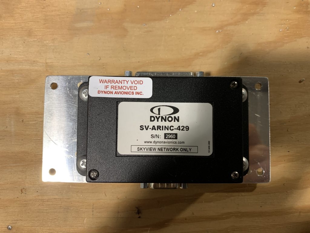
Cutting the plate was easy, as was getting the mount holes drilled for both the EMS and ARINC units. To help with potential interference with other stuff on the shelf, I positioned the ARINC unit off to one side (which, when mounted, means “higher up”) rather than centering it – this would provide more space near the shelf. Then I got my nutplates fitted and installed, and screwed the ARINC unit to the plate:
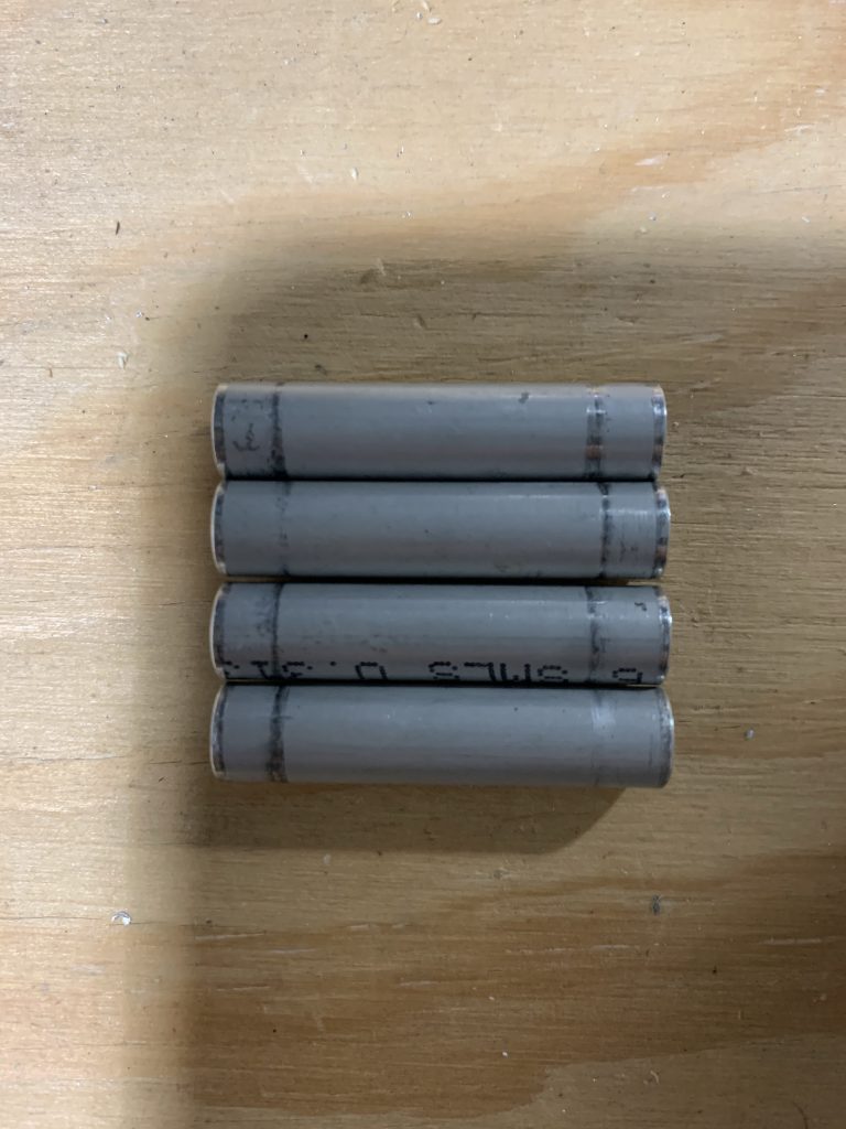
Next up were the standoffs. The mounting holes here are 3/16”, which makes this easy – I’ve got a bunch of aluminum tube that gets used for spacers on AN3 bolts like this all over the place. I even had a convenient donor piece: my first failed attempt at making the aileron trim pushrod. I worked out that the spacers needed to be 1 3/8” long to provide some space between the ARIND mount nutplates and the EMS unit, then did some cutting and finishing. And here we are, four nice little spacers:
Finally, it was time to put it all together! Only one problem: I didn’t have the right length of machine screws, since when I made my hardware order I wasn’t thinking of this application. But hey, I don’t need the actual hardware, I just need something to hold the assembly together so I can test-fit. I eventually found some AN3 bolts that would do the job, although they were way too long, thus requiring an absurd number of washers. Oh well, it gets the job done:
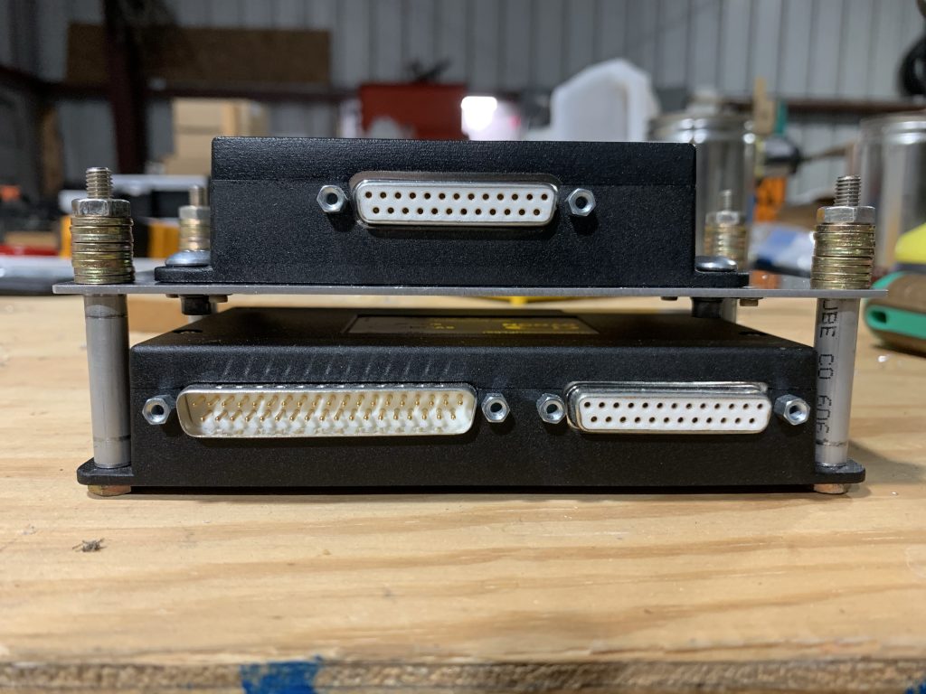
And so finally, it was time to go back and do the actual test-fitting…and hey, it works! I’d already decided earlier to move the CPI2 ECU over to the far right, mainly to provide better access to the fuses if needed. And that provides good room both fore-aft and up-down for the stacked units. It also lets me shift the voltage regulators back towards the center, which I like a little better…and maybe best of all, I can put the Skyview network hub over far right. That should make for some nice routing, since it’s 1) right beside the EMS and ARINC units, each of which have an SVN connection, and 2) convenient to the right HDX display, which is where I’ll start daisy-chaining the assorted panel units together, and 3) convenient to where the wire bundle going to the aft fuselage will exit the panel, which is good because I’ll have two SVN cables going that way from the hub (one for the roll servo, the other to tie into another network hub at the aft shelf).
I also rotated the CPI2 battery mount so its fuses face inboard as well, again for potential serviceability. The sole wrinkle here is that the Skyview backup batteries end up right between the ECU and battery for the CPI2 – this may make it tough to pull any of those fuses. But if that’s the case, I’ll always be able to remove the Skyview batteries if I need to – it’ll just be two plugs and four screws. Given that I don’t expect to be changing those fuses often, I think that’s acceptable.
This arrangement should also work well for potential servicing. The first step to working back here would be pulling the center panel unit – 12 mount screws to detach it, followed by seven plugs (one plug each for the two HDX displays, the GPS-175, the intercom, the radio head, and the AP panel, plus the SVN connector from the right-hand HDX display). I may consider trying to consolidate this into something like one or two cannon plugs or something, just for simplicity – I think that’ll depend on how all the harnesses end up tying together.
Anyway, back to servicing…with the center panel out, the entire upper shelf will also be removable, with about the same number of connectors: the two Skyview backup batteries, the D-sub and coax connector to the radio box, and the CPI2 connectors. The same thing applies here about maybe adding cannon plugs – that might be worthwhile to make this a little easier. I think the packaging for that might be more challenging, though.
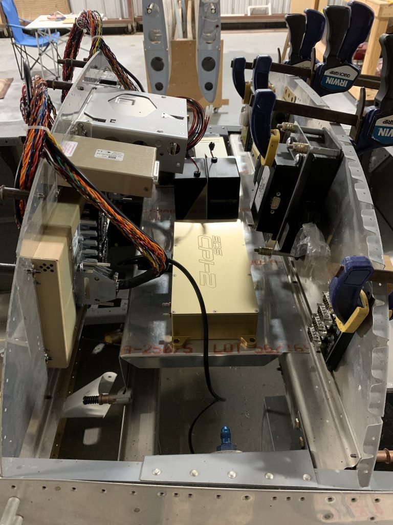
Anyway, let’s get to some photos. First is a look at the area from the left side of the aircraft. On the baggage bulkhead, we have the two regulators closest, followed by the EMS/ARINC stack – with plenty of space for those connectors. On the shelf, we’ve got the radio box, CPI2 battery, Skyview batteries, and finally the CPI2 ECU:
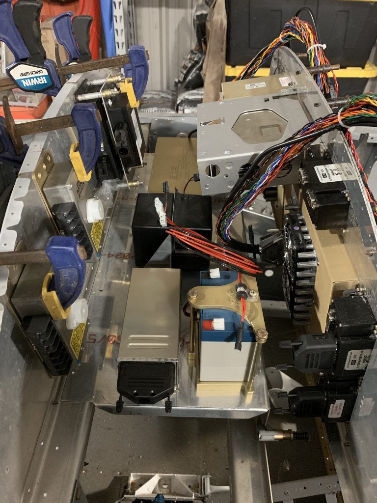
And from the left side…the only thing to note here is the SVN hub, which wasn’t visible from the other side. You can also see a black cable coming from the CPI2 ECU and sort of just going down by the gear tower. This is the cable that will tie into the CPI2 panel controller, which will be on the right wing of the panel.
So there we have it – not a lot of progress in terms of tangible stuff today, but I’m starting to develop a solid mental picture of how everything up here is going to tie together. I really think the next steps here will be to get the panel wings cut and drilled for their components, so I can mock things up a bit more. I’ve also got probably another Spruce order to work up – I need the longer machine screws for the stacked EMS/ARINC mount, plus also maybe some hardware for mounting the CPI2 ECU.
There’s also one more component to add, a pretty late addition – I didn’t even think about having a carbon monoxide detector until this past week. These are pretty ubiquitous in piston aircraft, and most often are just these cheesy little cardboard things taped to the panel. The accuracy of those seems to be questioned, they have to be replaced periodically, it takes up space on the panel, and it relies on me noticing a color change.
This is, of course, all a setup for something better I found – an electronic CO detector, which can mount behind the panel, and is compatible with the Skyview EMS unit. What this means is that 1) I don’t have to take up panel space and 2) instead of having to watch for a color change, I can assign audible alarms via the EMS system – so if there’s ever a CO problem, I’ll get yelled at in the headset the moment it crosses a set threshold. The good news is, the detector unit is really small, just 2” square – easy to fit in back here.
So I think I’ve got the mission(s) for the week: more panel cutting, working up that hardware order, and firming up the harness layout behind the panel. Nice to have a solid path forward.