Oh, hi. Looks like we just had another one of those dead periods where I randomly get out of the habit of building, and then just as randomly get back to it. At least I’ve kind of gotten used to this ebb and flow after all this time, and I don’t feel super guilty about it any more.
Looking back, I actually have done some work since my last post, but I guess I decided it wasn’t enough to merit an actual post. I say this because I’ve had a partially-sanded ridder tip for some time now; after slagging on that last batch of micro, I went back and started rough sanding it to shape, at which point I saw that it might actually be workable as-is to sand to shape.
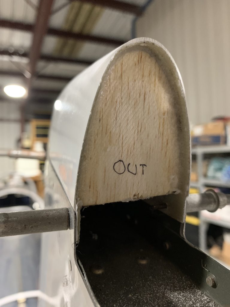
Thing was, for sanding to shape I wanted to use the v-stab tip as a sort of sanding guide to get everything nice and even – that is, I’d be sanding the rudder tip with both it and the stab tip clecoed in place – but for this to work I needed a way to immobilize the rudder in the centered position. Normally I’d do this by just clamping between the rudder horn and stab, but having a clamp over the top would block the stuff I wanted to be sanding.
After batting around a number of different ideas, I finally came up with something workable. What I’ve got are a couple pieces of scrap angle, with a hole drilled at one end that gets clecoed to the forward end of the horn, while the other end is clamped to the trailing edge of the stab. With one of these pieces on each side, the rudder is held very nicely in place.
Note: after taking this photo, and before actually working, I removed some material from the forward/upper end of the angles, so they wouldn’t protrude above the edge of the horn skin. Didn’t want that interfering with sanding at all:

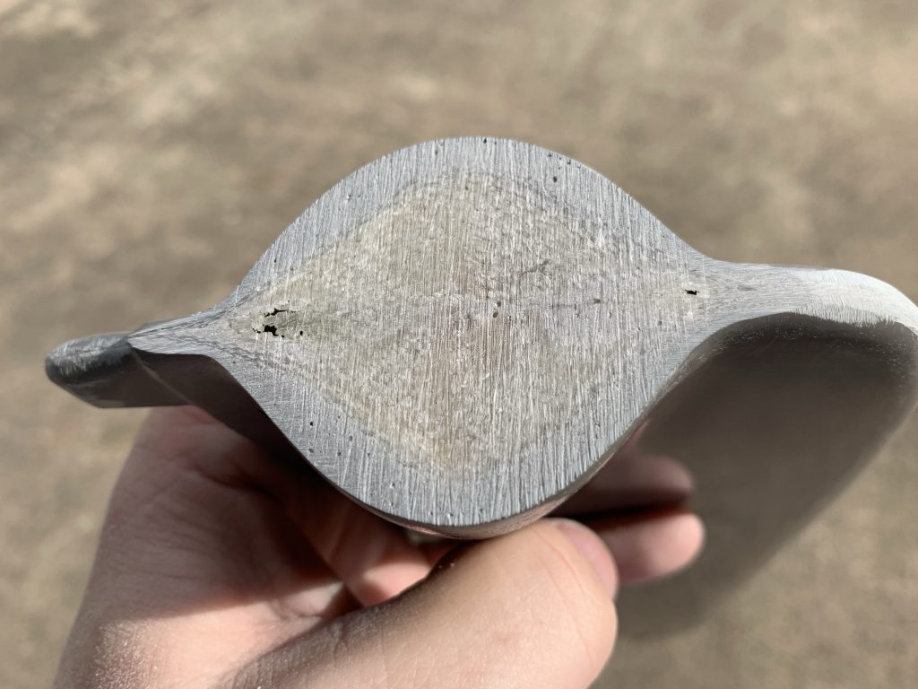
Next I applied tape to the stab tip so I could lightly touch it with the sandpaper as I worked without removing any material. Scratching here isn’t necessarily a huge deal, as I’ll be refinishing the tip anyway, but I only want to remove stuff from the rudder. Then I went to town with a sanding block, in lots and lots of iterations. In the end, I was able to sand it down to a nice matching contour, which sounds like good news, but the issue was that I found a number of voids (air bubbles) from when I applied the micro.
These are going to need to be filled, which means more micro, and I want to be careful about sanding two different batches of micro at once.Since mixing micro isn’t an exact science, the density of batches will differ, making even sanding possibly more of a challenge. This is probably something I’m being more concerns about than I need to, but oh well.
Additionally, I’m going to need to add some micro down near the flanges of the tip as well. While everything tucks up nicely at the leading and trailing edge, about mid-chord there’s a larger gap here, which I don’t want. So I’ll be figuring out a way to wipe some micro into this gap as well, which overall means that this tip is probably going to just get an all-over batch of micro.
This photo shows both the matching contour, a couple of the voids, and the aforementioned gap:

Anyway, I decided to make this into a sanding training project first and foremost. Even though I wasn’t going to use it, I spent some time with finer paper refining the contour and getting everything nice and smooth, just so get a feel for what I’ll be doing for real later on. Then I went back to 40 grit and proceeded to remove a ton of micro all over the thing, until the contour was about 1/8” below the stab tip. This is to give me the room to cover the entire thing with a coat of micro that I can then sand down. I also scuffed up the entire surface of the tip for proper adhesion of the micro.
Before I do this, though, I need to figure out how to get everything set up for the flange fix. I’m going to need the tip clecoed in place to pull the fiberglass and aluminum tightly together, but doing that leaves the clecoes really close to where I’m going to need to work with the micro. I’ll also need to cover the area with tape to keep the glass from sticking to the aluminum. I’m kind of tempted to temporarily pop-rivet the tip into place with 3/32 rivets, then drill them out later. I won’t have to worry much about munging the holes in the process, since they’ll need to be opened up to 1/8 for final riveting. Still, that’s a decent amount of work for a temporary assembly…
Next, I moved on th the rudder bottom fairing. Last time I added some more micro here to fill a couple pinholes and build up a couple areas. So this needs some sanding attention as well:

It took me about half an hour to work on these fun little compound curves, and get everything nice and smooth. I’m pretty happy with the overall contour here, so I think I’m about ready to go ahead and cut the hole for the tail light here, and get all the mount stuff taken care of.

Of course, I’ll also be wanting to probably scuff up the entire piece and shoot some filler primer. Question is, should I do that before or after I cut the hole? Bigger question, am I totally overthinking this? Based on personal history, there’s a good chance…