Wings

Pitot planning

Well, today was one of those days spent almost entirely on chin-scratching. It didn’t start off that way, but that’s just because there was some more cleanup work to be done. I didn’t get around to vacuuming up all the mud dauber debris yesterday, so I did that this morning, then worked on removing some of the highly annoying artillery fungus reside on the inboard spar ends. From my research, this stuff isn’t corrosive, but at least I can remove the highly visible stuff.

From there, it was time to consider what to work on first, and after rolling this around for a bit, I decided to look at the pitot mount in the left wing. This started with a bunch of VAF reading. The factory-recommended location for the pitot is in the same bay as the aileron bell crank, but that’s also assuming you’re doing the basic pitot tube – literally just a piece of tubing that sticks out of the bottom of the wing. Installing a more complex pitot, especially a heated AoA tube like mine, is quite a bit more complex. Instead of just one line, I have two, not to mention the wiring for the pitot heat controller.

Plenty of people have adopted other locations, generally moving to an adjacent bay, either inboard or outboard. Which direction is kind of hotly debated; some thing going inboard might get too close to the prop wash, others think moving outboard makes it likely for tie downs on the ramp to interfere with the tube. There’s the additional consideration that moving the mount puts the pitot further away from any of the access covers, potentially making maintenance more annoying.

Now, all that stuff I’ve read before, but I ran across a different idea entirely today – that of putting the tube way out near the wingtip. At least one person has done this and reports no issues, and others seem to think that it should be a fine location. It’s worth noting that this is where the pitot is located on some Grumman light aircraft. I really like this idea, for a couple reasons. First, it makes maintenance access super easy. Instead of working through a small access cover, one could just remove the wingtip and have good access through the rib lightening holes. Second, there’s no concern about routing wires and tubing in the vicinity of critical control systems (the aforementioned aileron bellcrank bay).

I haven’t decided for sure to go with this, but I did spend a whole lot of time looking at the pitot mount clamped in various locations in the spar. Assuming I do go with the far outboard location, I think I’ll end up positioning the mount beside the next-to-last outboard rib, like this:

The pitot tube itself, which fits into that mount, includes two soft aluminum lines, which will connect to the nylon lines that will route the pitot and AoA signals into the cabin. There must be a minimum amount of the aluminum lines left; since this is a heated pitot, there’s the concern of that heat damaging the nylon lines. My loose plan, in this case, would be to bend those lines toward the wingtip, and install a piece of angle in the rib lightening hole near the spar. Here, adel clamps would provide security and strain relief for both the line and electrical connectors. The pitot heat controller could simply be mounted on the outboard side of that outboard rib.

Will I do this? Yeah, still not sure. I need to check in on VAF, where I posed this question and I’m sure I’ll hear some reasons why this is a horrible idea. It remains to be seen if anyone has a convincing argument. Normally “follow the plans” is pretty good on its own merits, as a way to avoid additional work, but since fitting the pitot tube is essentially a from-scratch operation in any case, there’s no additional work associated with picking this different location.

So we’ll see. If I do settle on this spot, I’ll probably go ahead and bend the aluminum lines on the tube so I can get a more practical (ie less imaginary) look at packaging, and work more towards nailing that down.

Posted in Wings | Hours Logged: 3

More pitot planning

Well, not a ton done today or over the past week, though I did get to do some flying today (and also eat out for about the second time since March). I was able to spend a little more time looking at pitot tube position planning.

Last time we “talked,” so to speak, I was strongly considering mounting the pitot tube out by the wingtip. I did ask for opinions on VAF, and while nobody told me my idea was completely stupid, there was a somewhat general consensus of “but why?” I was approaching the question more from a “why not?” perspective, so I didn’t find this convincing.

However, the one obstacle to my planned location was figuring out how to tie the mount into the rib. The base of the mount rivets to the skin and spar, but it also requires bracing to the rib, to resist what I assume is a torsional load on the mount base, caused by drag on the pitot tube way out in the wind. Dynon provides a small piece of angle aluminum for this, but this presumes that the mount is stalled adjacent to the non-flanged side of a rib. My planned location was on the flange side, which would require me to get creative with this reinforcement.

But then I hit on a simple solution – still keep the mount at the second-most-outboard rib, but on the inboard side – then I could reinforce it as per normal. The only concern would be whether I could bend the pitot lines in such a way as to feed them through the tube and then through the immediately-adjacent lightening hole. Figuring this out required a practical exercise, and my initial plan had been to just go ahead and bend the pitot lines and experiment in real-time, shall we say.

But here’s the problem with that: those lines can be bent only once. So what if I bent them and eventually found my chosen location was no good? And then what if that bend was problematic for any alternatives? Clearly committing to the bend was not smart. I needed some sort of analog with which to test.

I spent some time poking around. Maybe some leftover fuel vent line? Huh, apparently I didn’t have any leftover. I have plenty of extra fuel line, but that’s twice the diameter of the pitot lines, and I’ll probably need more of it for fuel-system stuff down the road. Then the perfect thing occurred to me: the pile of Romex wire on a random shelf. The entire bundle is just about the same size as the pair of pitot/AoA lines. So I chopped off a piece the same length as the lines, and went to work.

The good news was that it was easy to figure out a bend that allowed for threading the lines through the mount, into the rib lightening hole, and out towards the wing tip. The bad news was that the lines only reached about halfway through the bay between those ribs. This would give me a new problem of needing to put some sort of support piece in the middle of the bay to support the ends of the lines, but the only thing to attach to would be the spar. Drilling a couple holes in it might not be the end of the world, but maybe still not a great idea.

That was pretty much the end of the wingtip idea. At this point much of the potential access benefits weren’t going to materialize, and there’d be significant mental energy in making this setup work at all.

This left two basic choices: either just outboard or just inboard of the aileron bellcrank bay. As mentioned before, the outboard location poses the possibility of interference with tie downs, but it’s also more difficult to access through an inspection cover, and also makes the bellcrank bay more crowded. So after lots more clamping the mount in various places and futzing with that poor abused piece of Romex, I settled on one bay inboard of the bellcrank.

So hey, let’s see some pictures. First, here’s that Romex, bent as appropriate to go through the mount. That 90° bend has to be pretty gradual to make it through the fairly-long mount:

And here’s a look at what the intended mount location looks like with he fake-bent tubes in place. On the other side of that rib from the mount is an inspection cover, so there will be good access here. The tubes can make a nice 90° bend through the lightening hole, and a piece of angle can be mounted to the rib to support both the tubes and the wiring from the controller. The controller will likely be mounted on the inboard side of that same rib, again easily accessible through the cover.

Overall, I think this will be just as accessible as my wingtip location, and significantly less complicated to implement. The nylon lines into the fuselage will be shorter, and can just run along the spar instead of through the conduit as I’d originally envisioned, which will make the conduit less crowded. And since this is all inboard of the bellcrank, I don’t have to worry about routing around that.

Although, as I type this, it occurs to be that the aileron push tube from the fuselage will go through that same hole I’m considering here…creating a potential interference. So I guess tomorrow I need to temporarily connect the tube to the bellcrank and get an idea where it’ll sit in here. That might be a dealbreaker, we’ll see. Maybe I’ll end up outboard of the bellcrank bay after all.

Welcome to the world of systems planning. Everything seems to affect everything.

Posted in Wings | Hours Logged: 1.5

P-p-p-pitot!

Yes, the pitot mount, again.

But first, a digression: I did have a good weekend. I’ve been “organizing” a local RV lunch for a couple years now. We used to rotate between two local airports with restaurants, until one of the airports was closed. So there hasn’t been a lot of variety. Josie and I have been talking about wanting to host a lunch at our hangar for some time now, and we were going to do it back in April, but then our good friend coronavirus came calling. But we finally did it this past Saturday.

Attendance wasn’t super great; I think the weather played a part, but I wonder if some folks are still hesitant about getting together. I missed some of my regulars. Still cool to have a few RVs parked on my ramp, and also to have an experienced builder look over my project and not mutter anything unflattering under (or over, for that matter) his breath.

Today was mostly a recovery day for me – I was up at 4 AM yesterday to get ribs on the smoker – but I got back to, well, staring at the wings and scratching my head. Last time, I’d pretty well settled on the inboard pitot location, but then wondered if the aileron push tube might be an issue. The short answer is “yes.” The tube runs pretty close to the spar, and is almost directly in line with the pitot mast, which makes it, at minimum, challenging to route the lines so as not to interfere.

Now, before I go on, I figure it might be helpful to show a bit of what I’m talking about with this setup. Below we have a look at the overall pitot system. The actual tube itself slips into the mast, and will be attached with screws. Protruding into the fuselage from the tube are two soft aluminum lines, one for pitot pressure and a second for AoA pressure. At the end of the aluminum lines are shown a couple of fittings, which provide the transition from the hard lines to the flexible nylon ones that will be plumbed into the fuselage. This particular pitot tube is also heated to prevent ice buildup and loss off airspeed; the wires are for the heat system, and connect to an external controller box:

Now, a lot of the packaging fun revolves around that transition from the hard lines to the soft ones. We want to secure the hard lines at some point to ensure they don’t rub against something (like the mouth of the mast) and get damaged over time. We also need to put some kind of a bend in those lines – at their current length, they contact the upper wing skin when the tube is inserted into the mast. This bend has to be pretty gradual, though, since it has to be able to feed through the mast. And that means I’m pretty limited in where I can place the ends of those hard lines – where, again, they need to be secured.

Now, if I can shorten those hard lines, I can gain some more flexibility here…I think. In fact, if I could make them really short, I could conceivably have the transition fittings actually live inside the mast. I’ve seen an install where the builder bundled them and wrapped them in self-fusing tape to hold them in place. With that approach, there’s nothing but nylon tube inside the wing, and a service loop can be added, so if the pitot tube needs to be removed, it’s simply removed to expose the fittings, and they’re disconnected outside the wing.

Remember, though, that the pitot tube is heated. And heat might be a problem for plastic fittings. Notably, the install with very short hard lines was not a heated install. I did a lot of poking around to see if there was any info on how long the hard lines needed to be to prevent damage to the nylon fittings. It seems that Garmin recommends a minimum of 8” for their similar heated pitot, but Dynon has nothing like this in their documentation – in fact, it says nothing at all about shortening the lines, either positive or negative.

Searching VAF yields some interesting discussion about just how hot the hard lines may get. At least one person has bench tested the tube and observed no real heating of the lines at all. Someone else pointed out, though, that this is a regulated heater – it only runs the heater as needed to reach a desired temperature, and in a warm shop, that might not be much at all. In the real world, in a serious icing situation, it could be running a lot more. Of course, there’s also the question of whether that cold ambient air will counter the heat buildup.

Anyway, what I’ve decided to to – but didn’t do tonight, because this idea came to me late – is to do some experimentation. I have a 10A 12V power supply, sufficient to power the tube. And if I make a decent-size ice bath to submerge the tip of the tube in, I should be able to simulate the worst-case scenario, where the heater runs at a high duty cycle. The ambient air will be much warmer than in a real scenario, which will make my measurements more conservative.

So that’s my next move…tomorrow. I connected the tube and controller to my power supply briefly tonight, just to confirm that the tube heats up. The main thing I’ll need to figure out is some way to hold the tube so it stays submerged in the ice bath. Stand by for some creativity…

Posted in Wings | Hours Logged: 2

Pitot heat testing

As alluded to last night, tonight was the time to do some data-gathering about the pitot tube. The first step was to find a container to make a suitably large ice bath. I wanted to be able to keep the pitot tube running and heating for an extended period of time, basically to allow as much time as possible for heat to make its way up the hard lines. Eventually I settled on the removable liner from the crock pot.

Then there was the matter of a fixture to hold the pitot tube. Here inspiration struck; I have a fixture I made eons ago for holding tubing in place in the drill press. It’s just a 2×4 with a pair of 45° cut blocks attached, providing a nice V-shaped pocket for tubing to rest in – and this made it also handy for resting a pitot tube in. I just needed a way to secure the tube in place, and for that I added a piece of scrap lumber over the top, with a couple wood screws to make a clamp of sorts.

Here’s the finished setup, ice bath and all: 

After applying power to the pitot heater box, I left this setup to run for about an hour, which ought to be plenty of time to get good heat soak. Then I measured the temperature of the hard line at 1” intervals, using an instant-read kitchen thermometer.

Now, something to consider here is whether or not I was testing the worst-case scenario here. I believe it does, since keeping the tip of the tube in an ice bath should cause the heater to run at its maximum duty cycle, as opposed to running it in ambient air, where the heater won’t need to do as much work. There is, however, the slight question of whether the ice bath would help to cool stuff upstream from the mast. One could probably have a lengthy debate about how well either of these scenarios resemble real life, but honestly, I’m not looking for real life…I want the worst-case scenario, to poke at an upper limit for heating of those hard lines.

Anyway, the end result of this is that I ran two tests: first, the ice-bath test, then a second one with the tube in the warm ambient air. The results were about as I expected, with the ice-bath test heating the hard lines more. But even in that case, they didn’t get very hot at all, barely north of 100°F even just a few inches from the pitot unit:

I haven’t had any luck finding a heat rating for the nylon tubing, but seeing as how 105° isn’t even outside the realm of possibility for a really hot summer day here in Houston, I don’t think it’s worth worrying about. Also, 5” is about as short as I’d possibly cut these lines, since that’s the length of the mast.

Long story short, I think I’m perfectly fine to shorten the hard lines and position the fittings inside the mast. This means I don’t have to worry about a carefully-crafted bend in the hard lines, or needing access to the transition fittings inside the wing for service. I can just provide enough slack in the nylon lines to pull the pitot out of the mast and disconnect the fittings out in the open.

That just brings us back to picking a spot. I really wanted to make this work at the inboard spot, but I just don’t like the interaction between even the soft lines and the aileron push tube. I know it’s been done, and I’m sure even if there is light contact between the push tube and the lines, it’ll be fine, but…again, I just don’t like it. I went so far tonight as to feed one of the lines out to mid-span to get an idea of what the packaging would look like, which reinforced that I’d need some tight bends to avoid the push tube.

So it looks like it’ll be outboard. I intend to secure the mount one bay outboard of the bellcrank/tiedown location. This should be far enough away to minimize potential interference from tiedowns, and still reasonably accessible from the access cover at the bellcrank.

Here’s a look at the packaging in the bay with one of the two tubes. The tubing will be routed through existing holes in the ribs, albeit protected with snap bushings in the final product. Not shown here is extra material for a service loop in this bay – I’m not sure if I’ll put that here or elsewhere.

Then we move one bay inboard to where the aileron bellcrank lives. I’ll want some additional hardware here to ensure the tubes are carefully routed between the bellcrank and the spar, just to absolutely ensure they never interfere with each other.

So at this point, I think this is finally settled, and I can now move on to the somewhat scarier – but less ambivalent – task of fitting the mount and cutting the hole in the wing skin.

Posted in Wings | Hours Logged: 1.5

Fitting the pitot mast…with extra fun

So…last night, I finally felt I’d put to bed the whole endless debate of where to put the pitot mast. Tonight, it was time to finally put an end to the thinking and get started on the doing. Amusingly, as we’ll see later on, I may have overdone the “put an end to the thinking” aspect.

The fitting of the mast is primarily done with the wing skin – locating and drilling the rivet holes between the skin and the base, and cutting the hole that the mast actually pokes through. For this, Dynon provides a nice little paper template. The instructions for positioning it, though, I wasn’t a huge fan of, at least for this application. They want you to draw reference lines on the skin and use those to position the template, but the matching lines on the template don’t go to the edge. I guess I could have trimmed the template, but…well, I didn’t.

Instead, since the existing holes between the skin and spar are kind of the starting point for the location, I used those to locate the template, holding a flashlight under the skin so I could spot the holes against the template and get it taped in place:

Next, I punched the rivet hole locations, along with the two holes that form the ends of the teardrop-shaped skin cutout, then used a razor to cut out the teardrop portion so I could trace it onto the skin with a sharpie:

At this point, the template can come off. First, the rivet holes are drilled in the skin:

Followed by the two holes to start the cutout:

Then it was time for lots of trial and error. I roughed out the cutout with a cutoff wheel in the dremel, then switched to a cutting bit to work out to the marked line, and then spent a lot of time slowly removing material with files until the mast would just slip through the cutout.

Next up was using the skin holes to drill into the mast base itself, and this meant clecoing the skin to the wing and slipping the mount in place. And this is where things got interesting. As soon as I had the skin in place, I saw the absurd mistake I’d made. The pitot was intended to be mounted at the outboard side of the bay just outboard of the bellcrank location. But I actually cut the hole one more bay outboard:

Now, you might think that I’d be pretty annoyed upon discovering this, but honestly, my initial reaction (and still my feeling right now) was amusement. All that time I spent trying to really carefully consider the location, to think through all the packaging, being really sure about it, and then cutting the hole in the wrong place. You can hardly write comedy that’s better than this.

Granted, one reason I can take this so lightly is because I decided to make the pitot attachments serviceable outside the wing. If I’d needed to service (ie connect/disconnect) those inside the wing, this would have been a pretty obnoxious mistake, as it would have been nearly impossible to get to those fittings. Here, though, my service loops for the wiring and lines will just live one bay further outboard. The only real concern is that the heat controller will still need to be mounted in the bellcrank bay, where it’s accessible through the cover. The included wiring between the two won’t be long enough to reach, so I’ll need to extend it. That isn’t a huge deal, though.

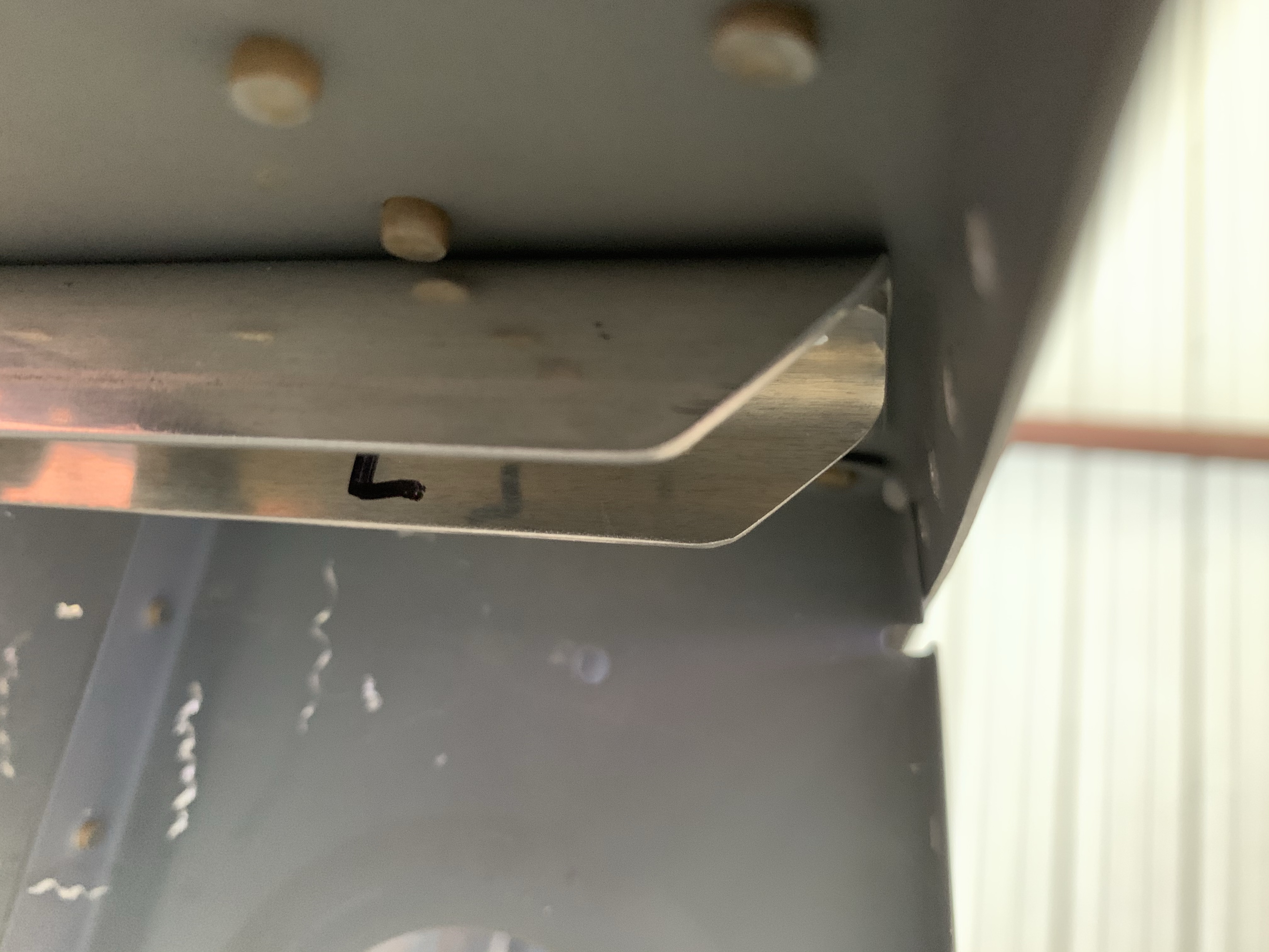
Anyway, after shaking my head ruefully a bit, I just kept on going with things. I drilled through the skin holes into the mount base, clecoing as I went, then removed the mount and skin again. The final piece of the puzzle here is a little piece of aluminum angle, which ties the mount base into the adjacent rib. This is needed to secure the mount properly against the air loads it’ll experience in flight. Simply having the mount riveted to the skin isn’t enough – the setup is pretty wobbly.

This part is pretty straightforward – the angle is first aligned with the aft most rivet hole in the base, and while held flush against the rib, that rivet attach hole is drilled. Then I just needed to drill a pair of rivet holes between the angle and the rib. To do this, I needed to ensure the mount was in place as if it were attached to the wing skin, but without the wing skin in place. No problem – I just secured a piece of angle across the ribs, then clamped the mount base to it. I drilled pilot holes in the small angle piece on the drill press, then used those as a guide to drill through the rib.

Here’s the final product, obviously seen without the wing skin:


This just leaves working out the heat controller location before I can pretty well call the pitot stuff done for now. Which I suppose means I’ll be moving on to performing the service bulletin on the aileron hinge brackets. And then maybe starting to make cardboard mockups of avionics and stuff so I can start planning wiring harnesses.

Posted in Wings | Hours Logged: 2

Pitot fittings; heat control packaging

Nothing too exciting tonight. I decided to keep working on pitot stuff, possibly going as far as getting the soft lines routed in the wing and prepositioned. First order of business was to trim the hard lines on the pitot and get them flared for the AN fittings. This sounds fairly simple, but it’s been a long time since I did any flares, and these are kinda critical, since they’re attached to a rather expensive piece of equipment. Put simply, requiring several tries to get these right wasn’t going to fly here, and so I did several practice flares using the pieces of line I’d cut off, and only then went on to doing the real thing.

And here we go, a pitot tube with the fittings in place. They’re not final-torqued or anything, just kind of there for now:

From there, I started thinking about what I’m going to do with the heater control box. The original plan had been to affix this to the outboard side of the bellcrank bay, where it’d be easy to access if necessary. That’s not quite as simple now, since I put the pitot tube one bay further outboard than planned – the wires between the box and the tube aren’t long enough to stretch across two bays. So that leaves me with a couple of choices. First, I could position the box one bay further outboard as well, retaining the ability to use the wires as provided, but making access far more annoying if I ever have to remove or replace it. Second, I could position it in the original spot, and extend the wires somehow.

If I do extend the wires, there’s the question of how I do that. Simply cut them and butt splice in wires, so I can retain the existing terminals? That ends up making maintenance still problematic, since I’d need to route that extended harness in such a way that it’s properly secured, but still removable without a ton of problem. Not quite sure those two goals can be easily reconciled.

Well, maybe I just create an intermediate harness. That does introduce more connectors, and thus more potential sources of failure, but at leas it mitigates maintainability. But using the same terminals on the harness is a problem. The spade connectors for the high-current wires are easy enough, but the two temperature sensor wires use a micro Molex plug, for which I’d need a special crimping tool.

Anyway, I’ll refrain from going through my entire thought process here, but this is pretty much where I’ve landed: I want the control box accessible, which means extending the harness. Since I’m already extending the harness, and since the pitot is now effectively at the halfway point between the bellcrank bay and the wingtip, I’m going to put the box at the wingtip. This way, it’ll be much easier to access for maintenance – I can just remove the wingtip, and have much better access to the harness routing than if I had to work through the access cover.

To extend the harness, I think I’m going to make an intermediate harness, which will be semi-permanently installed in the wing. I’ll use spade terminals for the high-current wires, and for the small temp probe wires, I’ll use a trick from SteinAir, where you put D-sub pins on each wire, and wrap them in heat shrink after connecting, thus making a secure but still detachable connection. These pins will work well for the tiny wire used for the sensor.

Of course, since I don’t really have any wire on hand, I suppose this means I won’t be finishing this harness any time soon. I’m starting to think I should pivot from wing stuff to really getting going on systems, so I can plan out harnesses and put together a big order of wire and other electrical stuff. So I dunno, maybe tomorrow I’ll start making mockups of boxes. It’s a good time to do so, we’ve got a fair amount of cardboard stacked up and awaiting a trip to the recycling center…

Posted in Wings | Hours Logged: 1.5

Aileron hinge service bulletin

All right – so over this past week, I’ve been kind of getting my focus refined. As I mentioned last time, the whole reason I got started with this systems planning exercise was so I could get a rough estimate of a wire order, and in turn be ready to get the wing wiring runs pulled. That goal has been achieved, and this past week I placed several orders for a bunch of electrical stuff – some crimp terminals for general use, what I hope are all the D-sub connectors and pins I’ll need, some Molex connector supplies (which I intend to use for the wingtip light connections), and last but not least – about three-tenths of a mile of wire. Seriously.

With that done, it’s time to refocus on the original sort of strategic task – getting the wings closed up. One task that kind of holds that up is completion of a service bulletin on the inboard aileron hinges. The service bulletin relates to spar cracks emanating from the rivets that attach the hinge brackets. The fix is to add a rather beefy doubler on the inside of the spar. Getting this done on a flying aircraft has to be a whole lot of fun, though it’s not required unless cracks are found. Since my wings aren’t closed up, and I have good access, I’m doing it as a preventative measure.

To start with, the brackets have to be removed, which means drilling out eight rivets per bracket. Nothing too exciting here, other than being really careful not to damage the spar. Fortunately, with the factory heads on the outside, if anything’s likely to be damaged, it’s the brackets themselves. That’s no fun, but it’s way better than mangling a spar and maybe having to build a new wing.

About halfway through taking the rivet heads off. Sorry, photo turned out a bit blurry:

After removing the heads and punching out a few rivets, and having the bracket come loose:

And here we are, a bracket-free spar:

Next up is fitting the doublers. Each spar has two doubler pieces, both made of heavy alclad angle material. One doubler covers the rivet holes on both sides of the bracket, the other doubles again (triples?) the outboard rivet holes. The result is a sort of U-shaped assembly on the spar, like so:

There is, however, a small catch here. Those doublers are nearly the height of the spar, and as such their ends sit pretty close to the spar. Multiple people on VAF have expressed concerns with being able to set the adjacent skin-to-spar rivets. Not only is there no room to get a bucking bar in here, some folks report there’s not even room to put a blind rivet in these holes.

Fortunately, Van’s has approved removing the corners of these doublers,. This doesn’t compromise the strength, and opens up a good bit more working room. It’s simple to mark and make the cuts necessary.

The doublers as delivered:

And after removing the corners for clearance:

After getting those all smoothed and deburred, it was time for some riveting, and before long, I had installed aileron brackets once again:

This was a really straightforward procedure, honestly moreso than I expected. I’d been dreading doing it a bit, I guess just from the general idea of drilling around my lots-of-time-invested wings, and maybe due to a little PTSD with how the horizontal stab SB went. Nice to get it all knocked out in a single day.

So now what’s next? Well, in the process of all that systems planning, I was thinking about how the wing wiring will enter the fuselage. There’s no holes in the fuselage in that area, other than the ones for the aileron push tubes, and obviously I’m not going to be running wiring through there. What I’d like to do is just have the wing conduit runs extend into the fuselage, with the wires then routed to their connection points under the seat. This, of course, will require adding holes in the fuselage sides, but the real fun has been trying to figure out how to locate them so they match the conduit locations. I can’t just easily hang the wings on there and mark it with a sharpie.

So what I’ve been thinking about doing is making a drill jig, which can locate off the rear of the main spar. I can fab this up using the wing as a guide, then put it on the fuselage using the carry-through as my reference point, and make my holes. it won’t need to be ridiculously precise, as I can make the holes slightly oversize compared to the conduit OD. It’ll still be a little nerve-wracking making that hole, though, especially since it’ll be months before I get to find out if I did it right…

I suppose something else I could be working on is fitting my landing lights to the mounts in the wings. Maybe I can get the nav/strobe lights mounted in the wingtips, too. Neither of these are really blocking closing out the wings, but they’ve gotta be done at some point, and I guess it might as well be now.

Of course, as I type this, it occurs to me that I’ll probably want to pull wiring for the roll servo in the right wing before I close it…which will probably work best if I have the servo on hand…I’ll at least want the bracket in there before I close anything…oh right, I need to pull the pitot lines in the right wing before I close it too.

OK yeah, there’s plenty to do.

Posted in Wings | Hours Logged: 3

Landing light mounts

So today’s task was to work out the landing light mounting. Way back when, I bought the Duckworks leading edge landing-light kit, and at that time I’d intended to use some sorta-nonstandard Whelen lights, and so the kit I ordered came with blank mounting plates – rather than, say, having an existing cutout for a PAR36 bulb.

In the intervening years, Flyleds became a thing, and I went with their combo light, which we’ve seen before. One of the nice things about this combo light is that it fits in a PAR36-sized cutout (though the unit is a lot deeper than a PAR36 would be), so it’d work great with that Duckworks mount…if only I had it. And in fact. I did consider just ordering two new mount plates, but in the end it seemed stupid to not at least try to cut the mounts I had.

And really, the task is pretty simple. Vertical positioning of the light is a no-brainer – just put it on centerline. The horizontal position is more interesting, though – the mount spans the entire bay in the leading edge, but the cutout is small, so the light obviously needs to be aligned with the cutout. So I spent some time with a ruler, reaching inside the bay, to measure the distance from each rib to the corresponding side of the cutout, and the width of the cutout itself. Armed with this information, I marked off the rough size of the light on the plate – a 4” square (technically it’s round but the square works fine for this). Then I installed the mount in the wing and verified the lineup. Actually, I did this twice, because the first time I measured a bit wrong and put the mark an inch off. Which is, of course, why we start with just marker…

This photo (and a few subsequent ones like it) is a bit awkward – the wings are still in the cart, leading edge down, so I’m basically shooting up from the floor to get this angle. Yeah, I did a decent amount of squirming on the floor today:

With the position verified, it was time to make the cutouts. I actually decided to make these about 4.25” instead of 4”, to provide a little more clearance for some of the components. This ended up being unnecessary, for reasons we’ll cover later, but oh well. My fancy hole-cutter tool, which hadn’t been used in some time, made short work of this:

Next I did some more positioning lines, which allowed me to position a light unit in each mount, and use the prepunched mount holes in the lights as a drill template for the mounts. This gave me my mounting screw locations, and allowed me to cleco the lights into the mounts for the first time:

Now, that photo – in particular, the way the lights are located behind the mounts – belies a whole ton of head-scratching. At issue was the question of how exactly these lights would be installed (and potentially removed for maintenance at a later time). Put simply, there seems to be no way for the lights, as delivered, to be inserted into the bay of the leading edge. There are two possible avenues here – in through the leading edge cutout, or through the lightening hole in the outboard rib.

It does seem to be possible to get the unit in through the leading edge cutout, but only with the taxi light projector removed. That would mean installing that thing inside the wing, a somewhat fiddly operation thanks to the long screws and springs involved (that is, the mechanism for aiming the light). I did not like this idea at all, so I decided that I’d plan on going in through the rib. The catch here is that the installation process for these will entail first installing the mount, then installing the light. That, in turn, means that if I’m putting the light in through the rib, it has to go behind the mount.

Still, there was the problem that the light wouldn’t fit through the rib hole either. The useful news here is that while the combo light circuit board is rectangular, the actual circuit traces are confined to a 4” circle. The rest of the board is fair game for trimming to fit a particular application, and that’s exactly what I did.

My original plan was to mark a circle just a bit larger than the mount cutouts, and use that to trim the boards, retaining two “ears” where the screw holes were located. This plan lasted about as long as it took for me to try and figure out how to trace the cut line with a marker. That was challenging enough, but making the cut would be not much fun either. So I decided to start small, and simply mark 45° cut lines starting at my potential mounting “ear” locations. I figured worst case, if those cuts weren’t good enough, it’d be material I’d be removing anyway for the circular cut idea.

Removing the corners still didn’t quite allow the light to pass through the rib, but by simply trimming a bit off the top and bottom of the boards, I was in business. It still takes some careful maneuvering to get the light through, but it’s doable. The resulting trimmed light unit has a sort of elongated octagonal shape:

This just left the question of attaching the lights to the mounts. Normally, if you were installing the lights from the front, you’d install nutplates on the back of the mounts, to receive the mounting screws. That wouldn’t work in this case, so there were two options: either install the nutplates on the front of the mounts, so the mount screws were installed from inside the wing, or install the nutplates on the light itself, so the screws would go in from the front. The latter seemed like a better option: first, I wouldn’t have unsightly nutplates visible in my landing light cutout, and second, trying to line up the screwed working through the lightening hole sounded like no fun.

So I drilled the lights for the nutplates and got them installed, and then, it was finally time for a full-up test fit. First, the mount went in, then the light, and the result looks pretty good:

From the back side of the bay, we can see that the heat sinks have plenty of room:

So that’s pretty much the end of this bit. The one remaining question is how I’ll handle the wiring for these; this is particular interesting since the wires for the three landing light projects attach on the front of the unit, while the wires for the taxi light attach on the rear. I intend to run all four wires to a single Molex connecter in the wingtip, and I’d like for the wiring pigtail to be removable along with the light unit; so I may have to get creative with that. Worst case, i guess I could just use two two-position connectors instead of a single four-place. In any case, I can’t really do anything with this until the wire comes in.

So now I guess I gotta figure out something else to do that doesn’t involve wire. Maybe I should dig up the aileron trim servo and see about getting that system done; I worked on that years ago, got frustrated, and moved on. Perhaps I’m better skilled now than I was then…

Posted in Electrical, Wings | Hours Logged: 4

Staring at things

I’ll tell you, the more time goes by, the more I really come to understand the whole “90% done, 90% to go” maxim among builders. In my mind, I have a whole roadmap of things to be done, mostly revolving around getting the wiring done. Yet every time I go to try and move forward on that, it seems like there are myriad little hangups preventing forward progress.

As of today, I’ve received all the wiring stuff I ordered. A whole lotta wire in various gauges and colors, an absolute boatload of D-sub components from SteinAir, plus the relay and diode I’ll need for tying the busses together. The general goal of this was to be ready to permanently install the conduit runs in the wings and get all the wiring pulled, and specifically the first thing I wanted to address was getting the pitot heat controller installed with its extended wiring harness.

And yet…after thinking about how to run the wiring from the controller to the pitot location, I’ve decided the smart thing to do would be to put in a short run of split loom conduit from the wingtip to the pitot bay. If I were to ever need to replace that wiring, this would vastly simplify the process. It also provides better wiring protection, and finally, enables me to satisfy a concern I had about the wiring service loop.

I’ll need enough slack in the wiring to allow the pitot to be removed from the mount until I get to the preinstalled disconnects. But with no good access to the pitot bay, the best I can hope for is just cramming the wire in there and having it floating around unsecured. It’d probably be OK, but the thought bothers me. With the conduit, though, I can keep the service loop normally at the wing tip, where I can secure it carefully. If I need to remove the pitot, I can just feed the extra wire into the conduit, providing the slack needed at the mount.

The downside is that, well, I need some conduit before I can move forward on that. The good news is that I can get that from Amazon and have it here early next week with free shipping. But it’s still a wait…

That brings us to the next hangup of the day. This started with me thinking about the holes I’ll need to cut in the fuselage sides to allow the main wiring conduit to protrude inside, but that moved into a different question related to the pitot tube. I’ve been planning on running the nylon pitot/AOA lines though snap bushings in the ribs alongside the main spar. But then I have to figure out how to get them into the fuselage. I can’t just make penetrations right in line with the line locations, because on the fuselage that’s where the spar center section structure lives. There’s an existing hole nearby, but that’s where the aileron push tubes pass through…routing lines through there seems unwise. So if I stick with location, I’ll have to route the lines in the tight space between the wing root and fuselage aft to some sort of passthrough.

The more I think about this, the more I end up back at my original plan, which was to route the lines through the wiring conduit. Then it can enter the fuselage at the same place as the wiring, thus simplifying everything quite a bit. Additionally, the lines can exit the conduit at the wingtip, and go through the same flex conduit as the controller wiring, and have the same service-loop securing setup as the wires. That has a nice tidiness to it.

The question just remains: how well will everything fit? Well, at least I now have the materials needed to make that evaluation. Something for tomorrow’s to-do list, I guess.

So that brings us to the one bit of tangible work for the day, though there’s an amusing twist at the end. This returns us to the question of making the fuselage penetration for the main conduit. A while back I came up with the idea of making a template that I could use to locate those holes, and tonight I decided to put that into practice.

Basically, the idea was to locate the conduit relative to the bottom of the aft side of the spar. This wasn’t too hard, just required some careful work with a try square, ruler, and other fun stuff. I then transferred my measurements to a piece of scrap 1×4, and drilled a #30 pilot hole. I figured I’d eventually use this to drill a pilot hole in the fuselage, which I’d then enlarge with a unibit.

With the pilot hole drilled, I did a visual test against the conduit bracket on the inboard rib, and it seemed to line up well, so I added the last piece: another scrap 1×4 piece screwed 90° to the other one. The idea is that this piece is slid into the center section and held against its aft side, providing the reference needed to locate the hole.

Here’s the finished piece, sitting by itself and then held in place on the fuselage:


Now, for the amusing twist: I’m not sure I’m going to use this after all. After attaching the 90° piece, I did another sort of test-fit against the end of the wing spar, and then it seemed the hole wasn’t lined up well at all. Granted, this is probably because I had to hold the piece much further from the conduit bracket, but that just made me think that there’s a lot of slop in this setup, and so my overall trust in it is pretty low.

I’m thinking that just figuring out a measuring scheme I can transfer to the fuselage is smarter. Maybe first measure the distance from the bottom of a wing rib to the bracket center, ensuring I’m square against the rib when I do it. Then I can make on the rib where the line intersecting the bracket hits the rib, and measure the straight-line distance from that to the intersection of the rib and the spar. That should be easily transferable to the fuselage, and seems more reliable than my template idea, which kind of feels like the old telephone game where intermediate reps end up garbling the original message.

I’m also thinking now about just seeing if Josie can help me…well…very temporarily install a wing on the fuselage. This would have a couple benefits: I could then run the conduit through the wing in question and directly trace its outline on the fuselage, and have a lot more confidence in the hole location. I could also measure the clearance between the inboard rib and the fuselage at that location, which would help me trim the conduit to final length, and thus eliminate a source of trial-and-error when the time comes to more permanently fit the wing.

Will I do it? I dunno, we’ll see if I still feel positive about the idea after a good night’s sleep. Though first I guess I’ll be finishing up my Amazon order…

Posted in Electrical, Wings | Hours Logged: 2.5

Mostly more staring

Once again, it’s been one of those days when all the effort seems to be mental, and very little happens from a physical standpoint.

One note from yesterday: after doing some reading, I decided against my idea of temporarily mounting the left wing so I could locate the conduit penetration. Sounds like that would be at least a three-person job, and I’m not sure the benefits would justify the effort and risk – besides, I don’t think there’s real reason to do it right now anyway.

To start the day, I decided to evaluate my idea of going back to running the pitot lines through the conduit, and I did this in the most practical manner possible – by cramming examples of the wires I’d need into the tube, along with the pitot lines. Here I’ve got two 12AWG wires (power/ground for the pitot), one 22AWG (pitot heat status), two 18AWG (landing/taxi light power), and the big shielded wire for the nav/strobe light units. It all fits quite nicely, so I declare this idea to be feasible. This at least settles one packaging concern.

Next, I moved on to looking at the pitot controller. I still can’t finalize the wiring run to the pitot location until I get some supplies, but I figured I could at least work on the connectors a bit. One problem here that had to be solved was with the two 26AWG white wires that go from the controller to the tube. These twisted pairs end in Molex micro-fit connectors, and a couple weeks ago, while trying to clumsily de-pin one of them, I pulled the wire out of the contact. I ordered a proper removal tool from SteinAir, only to find that apparently I need two of them to de-pin, since each pin has two tabs, and the tool only has one prong.

I’d already ordered the necessary parts a while back, including extras, so I just decided that I didn’t need to de-pin after all. I just cut off the old connector, crimped on two new pins, and installed them in a new connector. Done. Also good practice for when I build the intermediate harness later on.

Also, while I was in a crimp experimentation mood, I decided to give my D-sub crimper a try. I cut off a small length of 22AWG and grabbed pins, sockets, and a connector for good measure, all from my last SteinAir order. Crimping the pin was super easy, as was inserting it into the connector with the insertion tool I got from Amazon. Extracting it was a different story – turns out buying this tool from Amazon was a poor choice. The extraction end is malformed and unusable. So now I have a test pin inserted into a connector and I can’t remove it. Fun.

This pretty well transitions into what I spent the rest of the day doing, and that was compiling yet another round of orders. I knew I wanted a actual non-crappy D-sub pin tool from Stein. I also wanted to order the conduit from Amazon that I was looking at last night. Oh, and I wanted some cushion clamps to use for routing the wires at the wingtip, once I had all the materials to actually mount the pitot controller.

And of course, since I was ordering stuff, I wanted to maximize the utility, so there was lots of looking forward to other wiring stuff and adding items. In the process, I sort of firmed up my plans for components under the seat pans – mainly terminal strips for interconnects to wing wiring stuff, but also rough location ideas for the Flyleds controller boards for the nav lights and the landing light wig-wag function.

Now I just need to go actually complete these orders. The real question is, how many days will it be before I realize I need even more things? Also, how much of the cost of building this plane will have gone directly to UPS and FedEx? I don’t want to know…

Posted in Electrical, Wings | Hours Logged: 1.5