Empennage

H-stab fitting: Deep Thought edition

Well look, here we are after another break in getting stuff done. My excuse this time revolves around the two weeks we were out of town in early October, which of course 100% explains the six weeks it’s been since I did anything. I suppose being a little hesitant to actually commit to drilling holes figured in, as well. But today was the day to get moving again.

First order of business was to reverify that the fuselage was level and that the stab was clamped on straight and true. After all, it’s been six weeks since I did all this work. I was pleased to see that everything was still 100% kosher. So after triple-checking everything, I brought over the drill and drilled the four attach pilot holes between the attach bars and the rear spar. Whew – they ended up centered nicely on the spar reinforcement bars!

That was the easy part, though. The forward spar attaches with four bolts, which go vertically through a bunch of pieces. From top to bottom:

  • The horizontal stab’s lower reinforcement/attach angle
  • A thick spacer between the stab and the aft deck
  • The aft deck itself
  • The upper longerons (for the outboard holes) or a piece of spacer material (for the inboard holes)
  • A reinforcement angle riveted to the bulkhead

The good news is that all this stuff is pretty well fixed in place. Everything below the aft deck is riveted together, and the position of the stab itself is dictated by aligning it properly and squaring it to the fuselage. The spacers I’m a little concerned about, even though they’ll be tightly clamped when I drill, I worry they might move around.

The bigger concern here, though, is positioning the bolt holes – especially the outboard ones – such that they don’t compromise edge distance and thus weaken the structure. The plans give you measurements for laying out the holes, but being concerned about positioning, I decided to take some time to wrap my head around the layout and reason things out a bit.

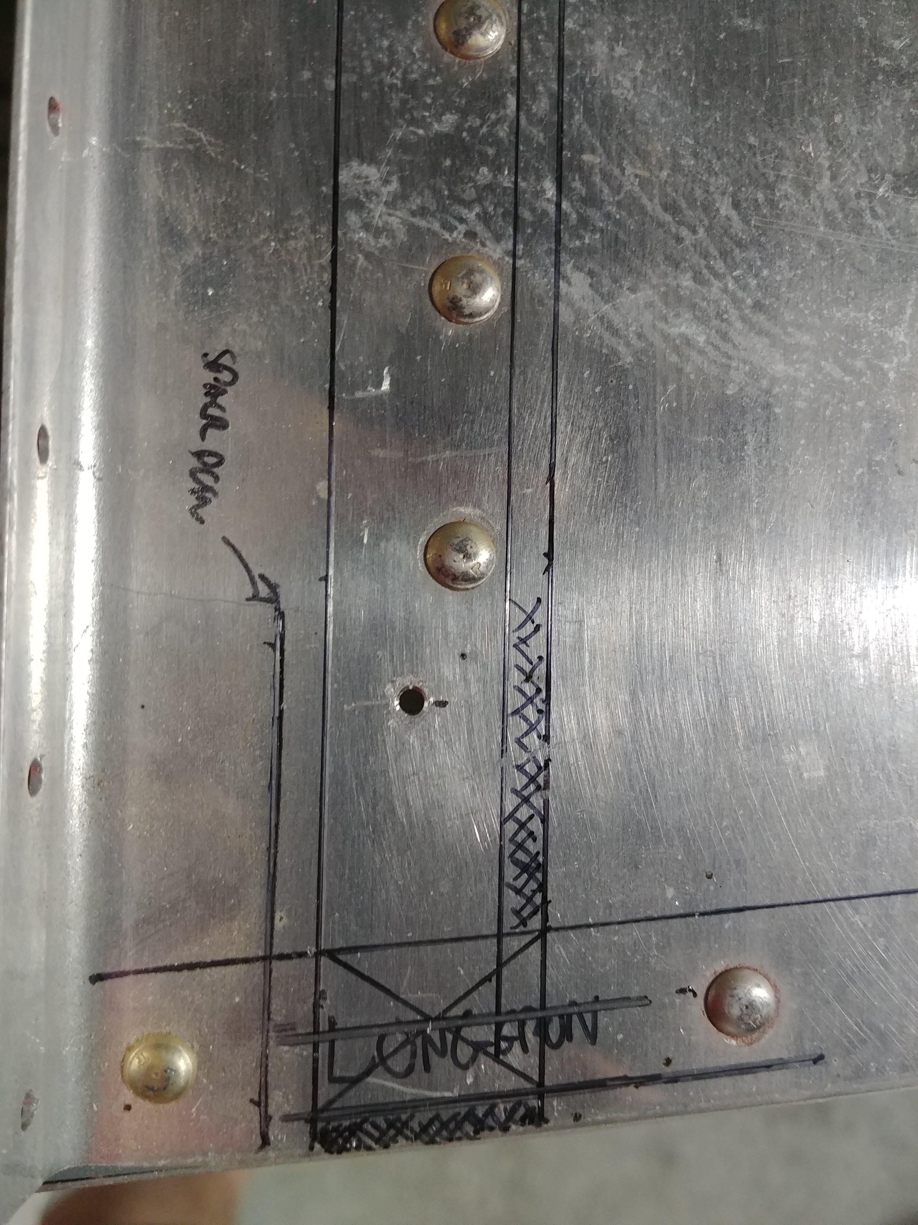
To start with, I removed the stab and proceeded to draw the outlines of the relevant pieces on the aft deck:

I also took those photos and made some annotated layouts with Photoshop:

Rv stab all

Rv tab detail

This is where it gets fun. By the book, for a 3/16” bolt hole, I’d want the center of that hole to be 3/8” from the edge of any part. But there’s only 5/8” of overlap between the longerons and the bulkhead angle, so the absolute best edge distance I can hope for here is 5/16”. The good news, based on my research, is that this is not a show-stopper, and in fact it sounds like almost everyone runs into the impossibility of getting “by the book” edge distance here.

Overall, I think I have a solid strategy here to make this as good as it can get, but this seemed like something where I should really let everything stew in my brain overnight before actually doing any drilling. I also posted to VAF just to get a sanity check from the peanut gallery there. It may even be possible that I’m way overthinking this.

So we’ll see how I feel about all this tomorrow, and what sort of feedback I get. I still have to decide how I want to drill the actual holes, even if I can lay them out nicely on the aft deck, I need to transfer those hole positions to the stab angle in order to actually do the drilling…
Posted in Empennage, Fuselage | Hours Logged: 1.5

H-stab fitting: making some actual holes

With last weekend’s track event behind me, it’s time to get back to work on this thing. Tonight I decided that I really wanted to actually get some holes drilled (but not at the cost of doing them wrong). Last time I’d put a lot of musing into figuring out how to properly position the bolt holes for the forward spar of the horizontal stab. I asked around a bit and got confirmation that my approach was reasonable. That just left the fun of figuring out how to actually drill the holes.

Here’s the fun part: with all the sharpie work from last time, I feel pretty confident about positioning the holes on the aft deck. The problem is, the holes have to be drilled with everything in assembly, which covers up all the fancy marks I made on the deck. Which is to say that if I drill from the top, starting with the attach angle, then I have to figure out some way to transfer the hole position markings onto the angle. Trying to work out a way to do this precisely was a real brain teaser.

For a while, I thought I had a bright idea: instead of drilling everything at once, carefully mark and drill the holes through the aft deck (and other attached stuff), then put the stab in place and use those new holes as guides to drill upward through the spacers and the attach angle. The downside to this approach is that it would require me to drill those holes from an awkward position, and I’d probably want to use the angle drill, particularly on the outboard holes. But a little investigation quickly showed that even with the angle drill, I wouldn’t be able to make the hole close enough to the sides for proper positioning. So that whole approach was off the table.

Finally, though (and when I say “finally” I mean “after 45 minutes of pacing around”), I figured out a solution. Here’s the real rub of trying to locate the holes on the stab attach angle: the reference points for the hole locations are the longerons, which sit under that angle. Trying to transfer those lines to the top of the angle seemed like a great opportunity to introduce error.

But…what I could do is transfer the location of the skin (which sits against the longeron) to the bottom of the attach angle, simply by clamping it in place, laying a ruler against the skin, and tracing that line on the angle. From there, I could mark out the hole locations on the bottom of the angle, drill the pilot holes there, and then use those holes as a guide to drill down through everything else with the stab in place.

That was a good approach for the two outboard holes, but the inboard ones were a different matter. The upper reinforcement angle makes it impossible to get a straight shot at the inboard locations from above with even a long drill bit. So for those holes, I decided to go with my original plan – drilling the initial pilot holes in the aft deck and using those to drill upwards through the angle. Since these weren’t right against the skins, there were no clearance issues using the angle drill.

And so I marked, measured, double-checked, verified, second-guessed, thought it all over again, re-measured with a different tool (I’m not making that up, that’s how OCD I was about getting this right), and then finally marked my holes and got to drilling. To ensure nice square holes, I made a drill block out of a chunk of poplar I had lying around.

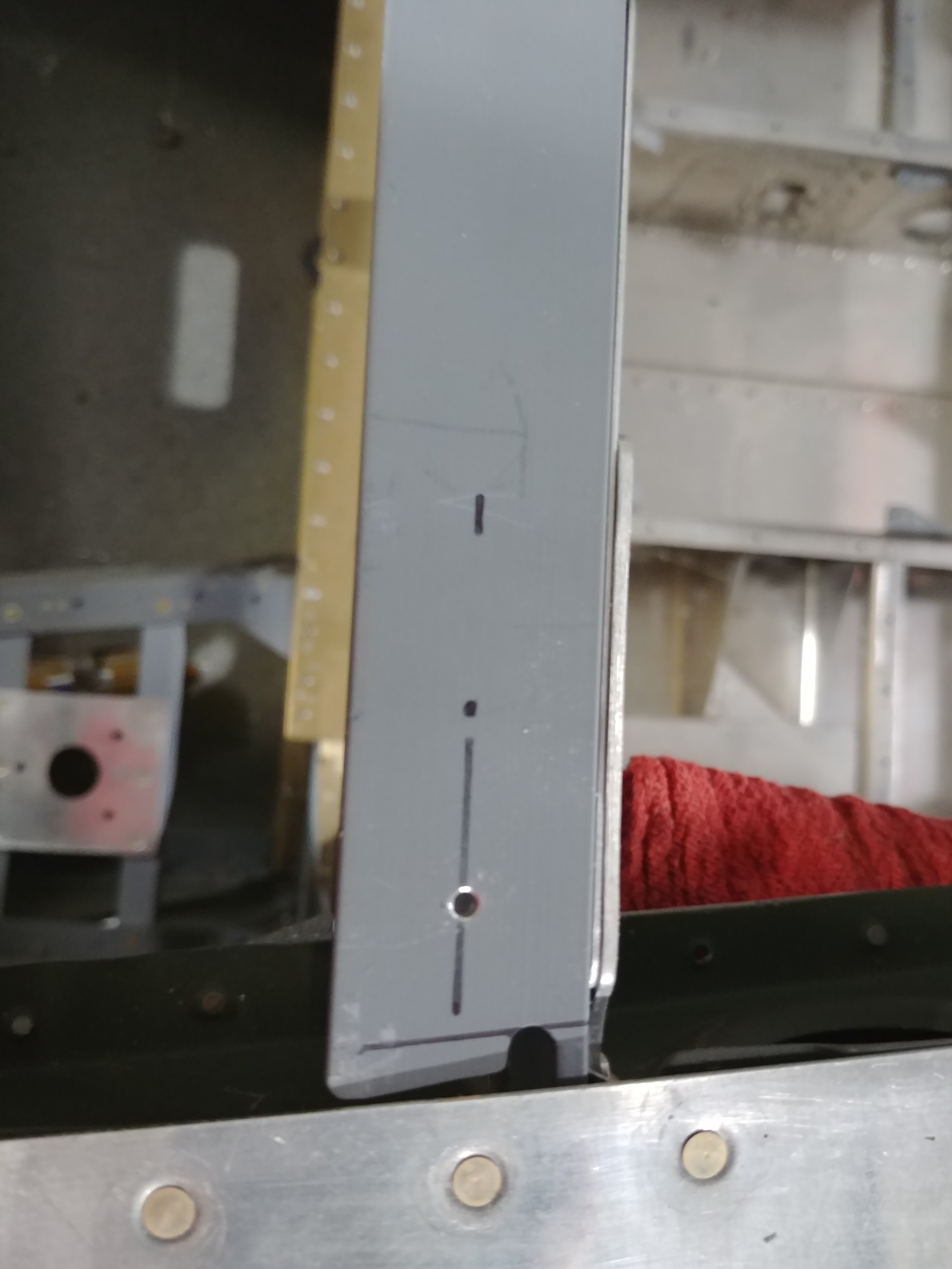
Here’s one of the outboard pilot holes in the attach angle:

And on a similar note, one of the inboard pilot holes in the aft deck:

Next, I put the stab back in place, clecoed it to the rear attach bars, squared it to the fuselage (again checking about 40 times), and clamped it tightly in place. The outboard pilot holes I drilled through using a 12” #40 bit and my drill block. The inboard holes I drill up from beneath using a #30 bit in the angle drill. Since these holes already went through about 1/4” of aluminum, I judged that the drill block wasn’t necessary. As I drilled each hole through, I dropped an old #40 drill bit in to ensure nothing wandered out of alignment while I was drilling other things.

Then I got out my inspection mirror and took a look at the hole locations beneath the aft deck, and they appeared to be properly located! That was a huge relief. I can’t even begin to communicate the amount of anxiety I felt before committing to actually making these holes.

But that’s not the end of this. The final holes need to be #12 for AN3 bolts, so there’s more drilling to be done. First, I wanted to drill them up to #30, at which point I could stop using old drill bits as alignment pins and use actual long-grip checks instead. The outboard holes were easy enough to drill up, just using a 12” #30 bit. The inboard ones were more interesting. I didn’t like the idea of drilling from underneath in this case (drilling to the next size up vs continuing a pilot hole), so I decided to drill from the top down. This required the angle drill due to tight clearance with the upper reinforcement angle.

And unfortunately, about halfway through the first hole, the gears in my angle drill adapter stripped out for some stupid reason. I’m a little grumpy about this, since this is the second adapter I’ve gone through on this build. Not sure what they make these gears out of, but I hope that same material isn’t in my airplane any more.

So that’s where the night ended – stalled pending the purchase of a replacement tool.

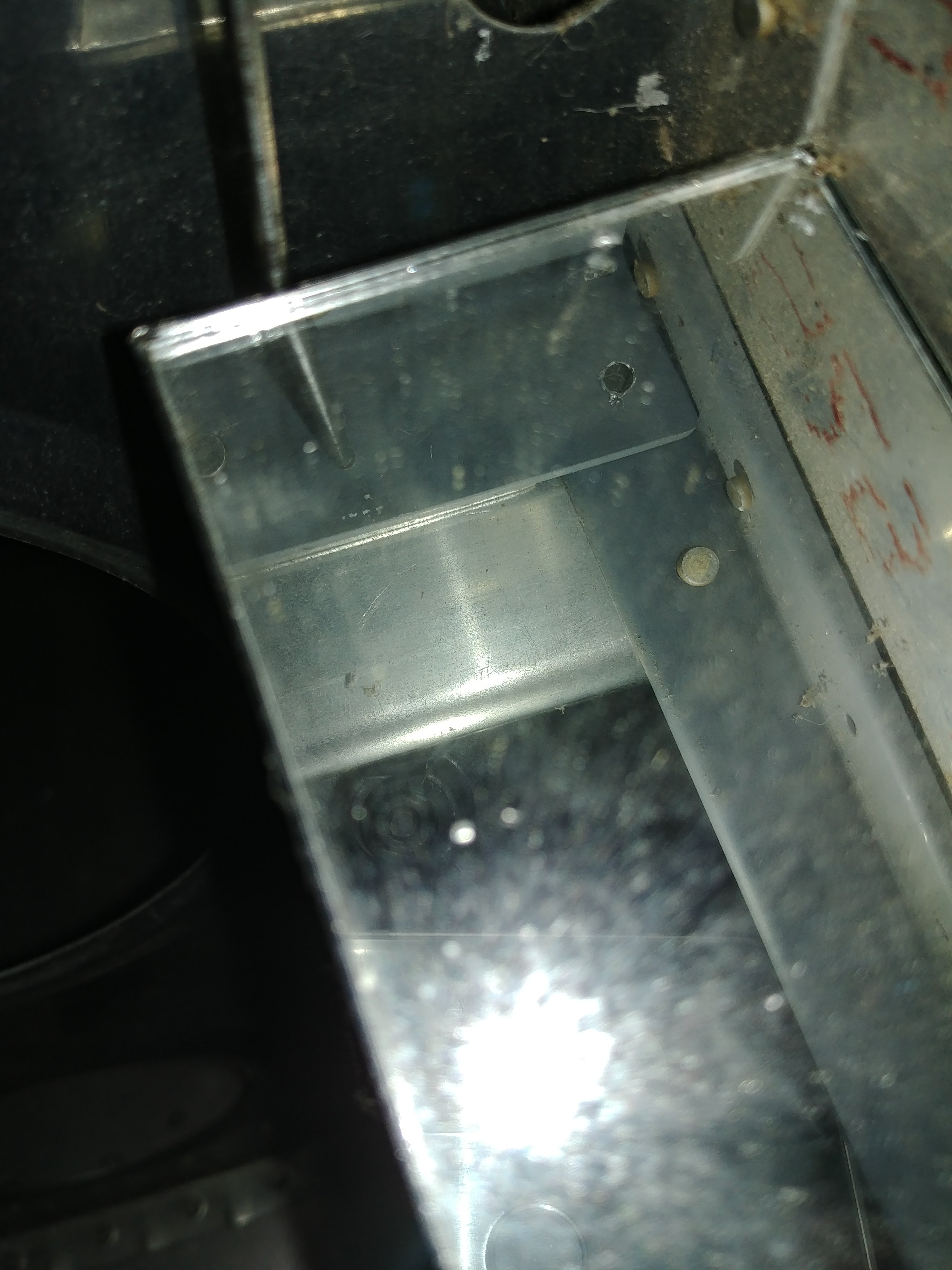
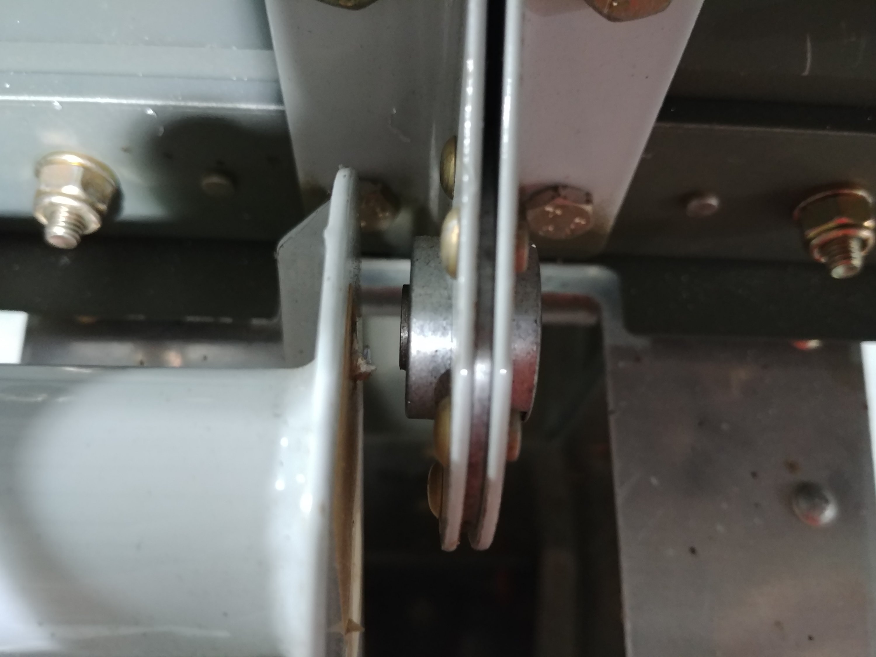
I’ll wrap up with photos from beneath of the holes. Here the outboard holes are drilled up to #30, but the inboards are still #40. Also, these photos aren’t great, but keep in mind I was using a cell phone to take a photo of an inspection mirror pointed at the holes. I think it’s about the best I could do short of actually getting in the fuselage.

Posted in Empennage, Fuselage | Hours Logged: 2.5

Elevator stuff

So tonight was kind of an exercise in not wasting time. After the failure of my angle drill attachment Tuesday night, I decided it was time to pony up and buy a real pneumatic angle drill – which I did. Thing is, until I get that in hand, I can’t do any more work on drilling the h-stab to the fuse. So the temptation was to just goof off until the drill comes in (tomorrow), but the reality is there’s plenty of other stuff I could be doing.

The first thing that came to mind was refitting the elevators. Back when I pulled these off prior to doing the stab SB, I lost the center bolt and the carefully-crafted spacers, and never could find them. I’ve since gotten a replacement bolt (rolled into another parts order), and so I decided that tonight I’d re-fab those spacers.

So I got the elevators hung on the stab, bolted them down, and then went looking for the spacer material. I thought that I’d done this before just using some of the aluminum tubing I have around, but when I went looking, I couldn’t find any tubing of the right size. The stuff I had fits nicely around an AN3 bolt, but this center bearing has an AN4 bolt.

So I went digging back through my build log, and it seems that when I tabbed these spacers up the first time, I bought some aluminum spacer pieces from a hardware store and used those. I guess I didn’t have any left over either, cause I dug through my parts bins looking for anything like that. This, in turn, put an end to any more work on making new spacers and re-fitting the elevators. I’ll have to make a stop tomorrow and see if I can find some suitable material.

In the meantime, here’s a pic of the stab and elevators mounted to the fuselage:

In a continuation of the original theme, I almost called it a night right there. But instead I looked forward to the next section after fitting/mounting the horizontal and vertical stabs, which is putting together the elevator control system. I spent the rest of the work session assembling the elevator bellcrank. Basically, this will be oriented vertically behind the baggage area. The pushrod from the control sticks to the bellcrank will run down low near the belly skin, whereas the pushrod from the bellcrank to the elevators will be mounted higher up, since it needs to go to the elevator horns which are also mounted higher up.

Probably this is going to go back in a bin until after I get the stabs mounted, which I should be able to pick up on this weekend, but look, it’s another part:

Posted in Empennage, Fuselage | Hours Logged: 1.5

H-stab fitting: done!

Welp, my shiny not-new (used) angle drill came in today. I picked up the materials I need to remake the elevator center bearing spacers, but I decided that I preferred to pick back up with the stab fitting and then circle back to the elevators later on. So I busted out the angle drill and had one of those “I should have bought one of these ages ago” experiences. It was so much easier to position this thing than the old angle drill adapter.

I had two more of the four forward holes to open up to #30, and then went back to final-drill them to #12, installing the attach bolts as I went. I did pause after the first #12 hole to take a look at its positioning, and it looks pretty decent (though maybe hard to tell from this inspection-mirror photo):

After installing all four attach bolts, I took another photo, using the front-facing camera on my phone, which ended up being unintentionally amusing and sorta creepy. But hey, the bolt positions look good:

Next up, it was time to dust off the vertical stab. This is actually the first time this thing has come out of the shipping fixture I built for it in Atlanta, about…um….six years ago. There were quite a few mud dauber nests to clean off of the thing, and then I had to remove the rudder and set it aside.

Technically, the first thing I’m supposed to do is trim the forward spar of the vertical stab, but I was about ready to call it a night, so instead I just settled for clamping the stab in place so I could get this photo:

Tomorrow I’ll have to do this in a more serious manner. Actually mounting this thing looks interesting, for some reason there’s a spacer piece that goes between the forward spar and the attach bracket to the horizontal stab, which should make it fun when it comes time to drill all this stuff in assembly. And I’ve gathered that drilling the attach holes in the rear bulkhead is fuuuuun.

We shall see.

Posted in Empennage, Fuselage | Hours Logged: 1.5

V-stab fitting: pt 1

I managed to get in a solid afternoon of work today, after meeting my brother and his wife for lunch as they were passing through town. As fun as it was to clamp the v-stab in place yesterday, the first order of business today was to take it right back off and move to the workbench, where I set about trimming the forward spar. It seems slightly odd to me that I have to do this – it’s not trimming to fit anything, it’s just a blanker “remove this much” directive. I guess maybe this part is shared with another model, and in that case the full length is needed? That’s all I can think of…

Anyway, with the spar trimmed, the stab got clamped in place yet again, this time in a more semi-permanent manner. The first major operation is to lay out and drill the bolt holes that attach the rear spar to the aft bulkhead. Initially, the rear spar is held on by a single cleco, on which it can pivot. This mean that before the bolt holes can be drilled, the stab has to be carefully positioned so it’s perfectly vertical. The method for checking this is pretty easy – just measure from the tip of the vertical to each tip of the horizontal, and tweak the positioning until the measurements are equal. And really, there’s not a lot of tweaking to be done – the lower portion of the rear spar just barely fits between the aft side skins, so there’s barely any room for movement. Once the positioning is set, then the rear spar is clamped tightly against the bulkhead to hold it in position. I, of course, rechecked the positioning after clamping, because I kind of expect everything to move when I’m not looking.

Now comes the really fun part – laying out the three lower bolt holes. I found the plans to be difficult to follow here, and even figuring out the easy part – the lower/center bolt hole – took some looking. Finally, I figured out that its vertical position was established by using a line drawn between two flush rivets on the bulkhead. The horizontal position was easy, it just went on centerline.

The top two were quite a bit more fun. In a similar situation to the h-stab, there are two critical pieces here that the bolts will go through. On the aft side, on the stab spar, there’s one half of a hinge bracket, whose edge faces downward. On the forward side, there’s the tailspring weldment, whose edge faces up. The bolts must pass through both pieces and maintain sufficient edge distance.

The plans give some measurements with which to lay these holes out, but they made no sense. In fact, they made little enough sense that I went inside to look at my electronic plans, suspecting that there might have been a revision – and I was right. The new planes were much clearer, though the overall guidance was “make sure to maintain edge distance on the bracket and weldment.” So I decided to dispense with the plans measuring meshing – which uses the low/center bolt hole as a reference, and gives a vertical offset – and instead plotted out the position of the tailspring weldment, drew it on the hinge bracket, and located the bolt holes midway between the two lines.

I did this by using a piece of aluminum angle, just long enough to sit on top of the auxiliary longerons in the tail, and I kept trimming a bit off one side of the angle until that side was flush with the top of the weldment. Then I was able to take that same piece, hold it against the hinge bracket, use the longerons as a visual reference, and draw a line. The rest was cake, just getting the midpoint lines and then a vertical line with the proper offset from center.

The resulting layout, center punched and ready for drilling:

These holes will be for AN4 bolts, so the holes eventually get to be 1/4”. I started with #30 pilot holes, again using my hardwood drill block to ensure square holes, then opened them successively to #12 and 1/4”. At that point, the stab came off again so I could deburr the holes and ensure nothing was getting trapped between the spar and the bulkhead, then it went back on and bolts went into the three new holes.

Next up was using the angle piece on top of the aft deck as a pattern and drilling two more bolt holes through the stab spar, this time for AN3 bolts. The bolts went into those as well.

Close up of the three lower bolts:

Longer shot showing all five of the bolts I made holes for:

That settled all the attach work for the rear spar, the next part is the real fun. The forward attach point must be carefully positioned, to achieve two goals: 1) centering the stab on the fuselage centerline and 2) keeping the rear spar straight – the hinge points need to be in line for the rudder to move freely. Working out all this positioning requires some setup work.

First off, as a reference for centering the stab, a string system is set up along the longitudinal axis of the plane. The manual calls for using a piece of wood or striaightedge across the rear of the spar, and running strings from either end to a centerline reference towards the front of the plane. I chose to use an 18” piece of aluminum tubing instead of wood; instead of having to tie two pieces of string, and ensure they were both perfectly position, I just ran the string through the tube and, from each end, to the front of the plane. By ensuring the tubing was properly centered on the stab, the strings would in turn be positioned correctly and incapable of moving. Centering the stab then becomes a matter of measuring from each string to the side of the stab, and moving the forward end until the measurements match.

Getting the rear spar straight is simpler; the manual calls for using a straightedge, but this seemed like a perfect opportunity to use a plumb bob and string as well. Just run the string through the hinge bracket holes, secure it at the top, and then keeping the spar straight just means ensuring the string stays in the center of the holes.

A couple pictures of the resulting setup:

I didn’t actually do any positioning work yet. I think i want to refine the longitudinal strings a bit (mostly getting them nice and taut) before I go measuring, and by this time it was about time to call it a night. So I’ll maybe pick up tomorrow with the positioning, and see how that goes.

This thing is looking more airplane-y by the day…

Posted in Empennage, Fuselage | Hours Logged: 4.5

V-stab fitting: pt 2

After attending the usual Sunday morning coffee club meeting here at Sport Flyers, and then enjoying some lunch, I got right back to work on getting the stab fitted. When we left off yesterday, I’d done the initial setup of the strings I’d use to properly position the stab. However, after thinking about the setup overnight, I decided to do some fine-tuning.

First, for the string going through the rudder hinge brackets, instead of having it hang on a plumb bob, I instead pulled the slack out and just let it be stretched between the top and bottom brackets. Using the plumb bob is good for checking true vertical, but I don’t need that – I just need to be sure the brackets are in a straight line. So stretching the string is actually better for that.

Second, for the longitudinal strings, last night I’d tried just tying the ends of the string to checks in the forward upper brace. The thing there is that the string isn’t necessarily perfectly positioned on the rivet holes, since it could come off the cleco on either side. Also, it was difficult to pull the string taut and get it clecoed, and I wanted some good tension on the strings. So I tied up two short loops of string, each one attached to a split ring, and hung one on each cleco. Then I tied my actual one string to one split ring, and tied a trucker hitch on the other one, which let me get some good, solid tension on the whole setup.

That meant it was time to start doing the actual alignment. The basic idea here is that the forward spar is clamped to the joint plate to the h-stab, and that interface can be moved laterally to fix the longitudinal alignment, and vertically to get the hinge brackets in alignment. But there’s a problem here – in addition to the joint plate (which is clecoed to the h-stab) and the rudder spar, there’s also a spacer between the two. And that spacer needs to be carefully aligned with the joint place. Well, this gets fun, because as you move the rudder spar around to get alignment going, the spacer moves around. And then when you try and move the spacer, the stab wants to move around. This pretty quickly seemed like an exercise in frustration.

So I came up with an alternative method. I placed scrap lumber across the top of the h-stab, under the bottom of the vertical, and used that to support the weight of the front of the stab. Since the bottom of the stab skin slopes downward, moving this lumber setup forward or backward moves the nose up or down, allowing the hinge alignment to be worked out. And the stab can just be moved laterally to get it properly on centerline. Small clamped hold the lumber in place on the h-stab, and two quick-grips on either side of the vertical prevent it from moving laterally when I don’t want it to. And the real payoff is that the spar doesn’t need to be clamped to the joint plate, so the spacer can be easily and carefully positioned without disturbing the position of the vertical stab.

A look at this setup:

And a look at the forward spar, with the spacer lined up properly and clamped in place:

Then it’s time to double- and triple-check the alignment before drilling. The string through the rudder hinges is bang-on:

Back up front at the joint plate, we’re just using the prepunched holes in the joint plate as a drill pattern. The bottom row is easily access with a long drill bit. The middle row requires the use of an angle drill. The top row seemed impossible to access with the stab on the plane, so I decided to stop drilling here, remove the stab from the plane, and drill the last four on the bench. Even then, I had to switch to a super-short #30 bit in the angle drill to get in here. The basic issue is that the forward spar and the root nose rib form an acute angle, making things tight.

Here’s the whole setup prior to me pulling it off to finish the drilling:

At this point, I was ready to just pull everything out, deburr the holes, rivet that joint plate and spacer on, and bolt the stab back on, this time semi-permanently (ie long enough to get some control systems put together). Unfortunately, when I removed the joint plate and spacer, I found a major problem. The bottom row of rivet holes is far, far too close to the end of the spar:

Minimum edge distance between a rivet and the edge of the material it’s in is 2x the rivet diameter from the hole center (or, by extension, 1.5x from the hole edge). For these 1/8” rivets, that makes the minimum edge distance from the hole edge 0.188”. The actual distance here varies from 0.129” all the way down to 0.103”. This isn’t just a case where things are a hair too close, this is a significant discrepancy – almost half of the margin gone in the worst spot. Moreover, these are the rivets that will hold the vertical stab onto the airplane, which is to say that they are in a structurally critical area. This is not a place where I am remotely OK with reduced margins.

Some searching on VAF reveals that this isn’t an uncommon problem (not surprising since you just blindly chop off some of the spar before fitting anything), and it sounds like the Van’s-recommended fix is just adding another row of rivets. There have been times when I’ve had a goof and reading secondhand Van’s engineering recommendations has been good enough for me, but on this case, I’m definitely going to email Van’s support and get a real, solid professional opinion.

Anyway, the end result of this is that that was the end of work for the day (I had other stuff to do around the house anyway). I’ll pick back up on the stab once I get a remedy from the mothership, and in the meantime I can probably go back to re-fabbing the center bearing spacers for the elevators. I’ll want to do that with the vertical stab off anyway, since its spar makes access to that area more difficult, and I need to work this out before I move on to rigging up the elevator control system.

Hopefully the Van’s office isn’t closed all week or anything like that…

Posted in Empennage, Fuselage | Hours Logged: 2

Elevator spacer stuff

So I did hear back from Sterling at Van’s today – as expected, there’s a simple fix for my edge distance issues, and it’s just adding another row of rivets. But for tonight, I decided to go back to working on the elevator spacers. My reasoning here is that once I get the vertical stab squared away, I’ll want to bolt it back onto the fuselage, but having it there will make access for the spacer stuff annoying.

So on to that topic – here’s a look at the center bearing area, with just the left elevator in place:

Of interest here is the gap between the bearing itself and the elevator horn to the left. This is the gap that needs to be filled with a spacer. A missing or badly-sized spacer would mean that, when the bolt through the center bearing is torqued down, a side load is placed on the other elevator hinge bearings. The plans call for stacking washers here, but the preferred method for getting really nice elevator movement is to fab up spacers to really get the thickness precise.

So I went to town on my little aluminum pieces from Ace, worked them down to size, and then installed the bolt through the center bearing. Wheee:

However, things aren’t quite right here. With everything torqued down, the elevators move without noticeable effort, but stop immediately when I let go. I’d prefer to have them move a bit more freely. I don’t think this is an issue with the spacers, though, especially because when I placed the center bearing bolt, I had to work it a bit to go through the horns and the bearing. Not a lot, but I suspect even that bit of force is enough to bind things up just a hair.

To verify this, I decided to remove the bolts through the middle hinge point on each elevator. This was to test the idea that one or more of the elevator rod ends (which serves as the hinge on the elevator) maybe needed adjustment in or out – that is, all three holes weren’t in the same axis. And I found that with those two bolts removed, the elevators moved quite freely.

I think I may just need to go out half a turn on both inboard rod ends…but doing that means removing some annoying bolts (especially the center bearing one), so I called it a night rather than go further down that rabbit hole. Unfortunately, getting this right is just going to require some tedious trial and error.

Posted in Empennage | Hours Logged: 2

More elevator work

Not a lot of time in the shop tonight, but I did get the elevators fixed up where they move freely. After some more experimentation, I determined that the right elevator was OK, and it was only the left one that was binding up. I arrived at this conclusion by torquing down all the hinge points, then loosening the center bearing bolt. When that’s tight, it pretty effectively ties the elevators together, so it’s hard to tell if only one side is binding. With it loosened a bit, the right elevator moved freely, but the left one still wanted to stick a bit.

I ended up pulling the left one off and bringing each rod end in half a turn. After that, getting the center bearing bolt through was a lot easier, verifying my suspicion that that was the source of the binding. And once I torqued everything down, both elevators move nice and free now.

And yes, it really took an hour to do this. Installing and removing every single one of these bolts is tedious, especially the center one.

Next up: finishing and installing the vertical stab, then some control system work.

Posted in Empennage | Hours Logged: 1

V-stab mounted, elevator horns drilled

So in between smoking a turkey, eating said turkey, taking the obligatory post-turkey nap, and giving the parents a call, I did find some time to get out and work on the plane.

First up was picking up where I left off on the vertical stab. I laid out the four extra rivet holes, as directed by Van’s to account for the edge distance issues, drilled them in the splice plate, and then used those as a guide to drill through the spacer and spar. Then I deburred the new holes before riveting everything together:

Then it was back over the fuselage, where I bolted the stab in place, semi-permanently this time:

Next up was drilling the elevator control horns for the pushrod attach point. These holes aren’t pre-drilled, as the horn parts frequently have some variance in them; it’s for the same reason that the pivot holes in the horns are drilled in assembly as well (waaaay back in the empennage build phase).

To start with, both elevators are clamped into a neutral position, in line with the stab. The position of the horns is examined, and the one that’s furthest back is chosen as the on to drill the first hole in. The reason for this is that the hole is laid out relative to the forward and bottom edges of the horn, to ensure proper edge distance. Since the second horn will be located further forward, we can be sure that the edge distance there will be OK as well; if we did it the other way, we’d potentially have an edge distance violation on the second horn.

Anyway, in my case the right horn was further back, so I laid out and then drilled the bolt hole there (note that here I’ve moved the left elevator to get its horn out of the way for the photo):

The next challenge is to drill a hole in the other horn in the matching location. The problem here is that there are a couple inches between the two horns, so we need to make sure that we drill straight across. To do this, a drill guide block is made from hardwood. In my case, I reused the piece of poplar that I’d previously used as a drill block for the horizontal stab. I had to trim it a bit to get it the proper width for a snug fit between the horns, and then I drilled a new 3/16” hole using the drill press to make sure it was properly square. Then the block gets clamped between the horns, in alignment with the first hole:

And then the hole gets drilled:

And that’s it – a quick pass with the deburring tool to clean up the holes, and these guys are now ready to accept the pushrod, which I’ll be fabricating next.

Posted in Empennage, Fuselage | Hours Logged: 1.5

Pushrods. That’s all, just pushrods

No, really, that’s all I did today, just work on pushrods.

First up was the large pushrod that will go from the bell crank back to the elevator horns. This one is made from large-diameter, thin-wall tubing. Just trim it to length, clean up the cut area, fit the rod end inserts, then mark and drill the holes. Marking the holes is kinda fun, you just stretch a strip of paper around the tube, fold it three times to make eight sections, then wrap it around the tube again and mark where each crease is – and now you’ve got eight evenly-spaced holes!

See, look, paper:

I recruited Josie’s help to get those holes drilled – trying to support the entire rod (which is a good 5’ long) while positioning it precisely at the drill press isn’t really a one-person job. Then there was a lot of priming, followed by some riveting, and this thing is done:

Next up, basically the same process is repeated for the smaller of the two pushrods; this one will connect the bellcrank to the rear stick. This one is smaller-diameter tubing, but with a thicker wall, and the rod end inserts here are male instead of female. Additionally, the inserts here are plated, unlike the previous ones, so they don’t need priming. I got as far as drilling the small one, cleaning it up, and priming the outside tonight. I figure I’ll let that dry overnight and tomorrow I can deal with priming the inside and getting those inserts in place.

In between priming the second pushrod (ie while letting the coat on one end dry so I could then hold that end while priming the other one), I grabbed the third pushrod of the night, which will connect the front and rear control sticks. This one, at least, is prefabricated, with the inserts already in place and the whole thing powdercoated. All I had to do was thread in the proper rod ends. Well, actually first I had to clean the thing, because mud daubers had built nests in both ends of the thing. I ended up having to run a tap through the inserts to get all the crud out.

But hey, now this one is done too:

And that’s it for tonight. Maybe tomorrow I can get that second pushrod done, and then move on to prepping the actual control column, which I believe is the next thing on the list. Which will put me a little bit closer to actually rigging the controls and making control surfaces move…

Posted in Empennage, Fuselage | Hours Logged: 3