Electrical

More grounding prep

Just a brief session tonight. Earlier today I sola fantasized about getting all the ground terminations done tonight and powering things up before the weekend, but it didn’t take much looking out in the hangar tonight to realize that was hilariously optimistic.

I got the newly-laced bundle pulled down into the gear tower and through the hole towards the firewall – kind of a pain really since all the masking tape tags made it impossible to just feed the bundle through as a unit. Between that and feeding a snap bushing over the end of the bundle to put into that hole, the result was a pretty tangled bunch of wires that needed some attention.

Next I sat down with the label printer and went through all those wires, putting in the labels for them. Kinda fun keeping track of which of 30-some wires I have and have not typed in already. Plus there were a couple tape labels that I was no longer sure what they referred to, so I ended up referring back to the schematics a couple times, just to make sure I was labeling things properly. Then I printed out a loooong string of heat shrink.

Before I trim anything to length, I want to get an Adel clamp mount point into the auxiliary longeron, since this bundle will need securing. That’ll let me get the general routing of the bundle down pat, and then I can start thinking about trimming. It’s going to be fun doing this since the area between the gear tower and the firewall is a bit snug.

Posted in Avionics, Electrical, Fuselage | Hours Logged: 1

Grounding: securing the bundle

Another no-photo night, I’m afraid. I decided to work on making provisions for securing the ground bundle. I already knew I’d be adding an Adel clamp on the auxiliary longeron forward of the gear tower, but I was debating also putting one on the forward brace above where the bundle goes down into the tower. The latter would be similar to what I did with the larger bundle coming up out of the right gear tower; on this side, the bundle was much smaller, but eventually I decided I wanted it secured as well.

Getting the nutplate mounted on the brac was pretty straightforward, though it still required the angle drill and some other creativity. The longeron was a lot more fun – initially I thought about just drilling the screw hole and using a nut instead of a nutplate, but I really didn’t like the idea of needing two hands to get the thing secured, so I went with the nutplate mount here too.

Unfortunately I didn’t finish that mount. The aux longeron is kinda fun to work on since it butts against the curved forward side skin – this means getting a tool aligned with a hole can be challenging. I already knew I’d have to make the rivet countersinks by hand, but I couldn’t even use the long shaft with the countersink bit here. Eventually I rigged up a combination of a hex adapter, 1/4” socket, wobbly joint, and a few extensions. That worked but it seemed like it’d take forever. So I added an adapter and my T-handle wrench, which let me put more torque on the setup.

That turned out to be a bad combination – it was hard to keep the bit well aligned, but easy to overcome the resistance from bad alignment with the T-wrench. The result was that I snapped the tip off my countersink bit on the second hole, and that tip remained lodged in the hole. I worked on extracting it for a while but eventually decided that I was getting to the point of causing damage if I kept trying to force the issue. Hopefully revisiting this in the morning, I’ll have better luck.

Posted in Avionics, Electrical, Fuselage | Hours Logged: 1

Grounding: terminations

Started off today revisiting that countersink bit chunk that was tuck in the longeron hole. At first I wasn’t getting anywhere, but eventually instead of trying to drive the thing out, I got a fresh bit and tried using that to push the broken off part out from below…and it popped right out. Should have tried that a while back, I guess.

I still needed to finish the countersinking, but overnight I had a real forehead-slapping moment about this job. Yesterday I was trying to work out some really crazy ways of running the countersink bit by hand. I thought about trying to just run it in the angle drill, but was thinking of threading the countersink into my thread-hex adapter and then chucking that in the chuck adapter for the angle drill, and thinking that would all be too bulky. When I thought of it the way I just typed it, though, I realized my stupidity…I could just thread the countersink bit directly into the angle drill…duh. With that realization, I finished the countersinks and riveted the nutplate in no time, then got the adel clamp loosely attached, just to keep the wire bundle roughly in place.

Then it was time for some terminations. First was the short pigtail for the fuel pump – I’m using handshake splices for this connection. It occurred to me today that blade terminals might be nicer down the road, but I don’t have those in the right sizes, so handshakes it is. I needed to do the pigtail first because the fuel pump ground was the last wire to add to my bundle – I temporarily removed it while pulling the bundle through the gear tower. While working on this stuff, I also went ahead and laced the bundle up to and a bit past where the pump pigtail comes out.

Finally, there was nothing left to do but to start trimming and terminating the actual grounds. I got through eight of them (out of, I think, thirty-some) before calling it a night. These went pretty quickly, so I’m feeling confident about wrapping the rest of these up tomorrow – though there will be some pauses to handle lacing up the bundles. I want to go a little beyond just lacing the big bundle until it splits to individual ground tabs, maybe lace together batches of eight or so just to provide some vibration support closer to the tabs.

But hey, I finally have a photo again:

Posted in Avionics, Electrical, Fuselage | Hours Logged: 1.5

Grounding: DONE

Got a nice early start this morning before it got stupid hot outside. I managed to finish up all the ground terminations by 8:00, at which it was time to stroll across the runway for Sunday Coffee Club. That was followed by several hours working on a Helio Courier that was donated to the Waller County Aviation Museum. Finally, I got back out and finished up the cable lacing and securing in the ground bundle area:

 At this point, I decided it was time to work towards actually powering up the panel. There was still a decent amount of work to be done before that, mainly from a quality-control (read: avoiding release of the magic smoke) perspective. What I decided to do was to disconnect every avionics connector in the airplane, apply 12VDC to the fuse blocks (with fuses installed, of course), and probe every pin in every connector, confirming that only the ones that were supposed to have 12VDC had it. After all, I figured the most likely cause of magic smoke release was putting bus voltage somewhere it didn’t belong.

That bit of testing took some time and was pretty tedious, and I also did the same testing for good grounds, ensuring everything was kosher. I also built out coax cables for the com radio and GPS-175 – I didn’t want any chance of something being damaged by powering on with no antenna connected. But finally, I had the panel and avionics shelf in, everything in place, and the main bus block tied to the power supply. I looked everything over one more time – that’d be a lot of money to ruin – took a deep breath, and flipped the switch.

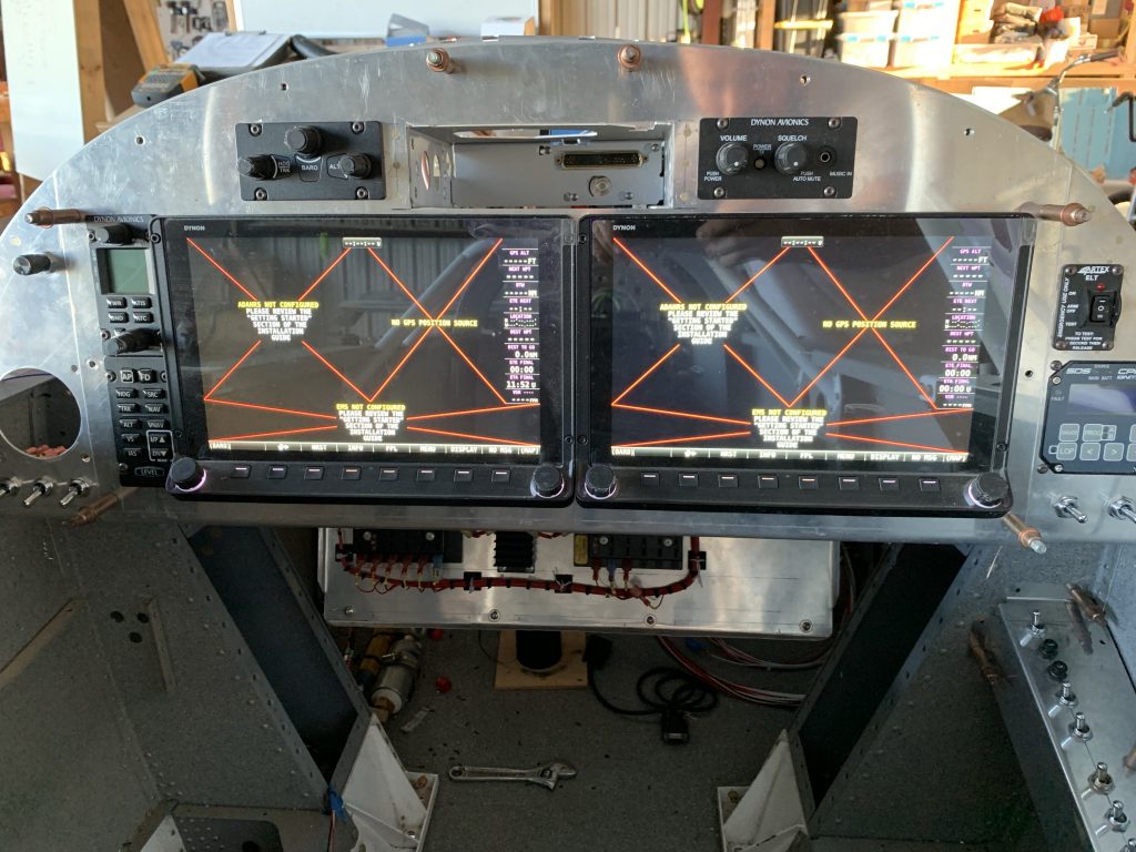
What I got was not what I expected at all. A couple units flickered on briefly, and one display showed a splash screen for a moment before going dark. Was this the normal boot sequence? Nope, another flash, another brief splash screen, nothing. This seemed indicative of periodic voltage drops from the power supply, and checking across the terminals with my multimeter confirmed it – the drops were large enough to be noticeable on a relatively slow-responding digital multimeter.

Strange – this was a 12A power supply, and by the book all the avionics together should draw under 6.5. But still, I started pulling fuses – maybe I just needed to shed loads a bit. I eventually got down to just the two HDX displays, but still got the same results.

A this point I gave up and went inside for dinner. After thinking it over, and chatting a bit on a phone call with my parents, I decided to try one more thing – bypassing the fuse blocks entirely, and trying to only power a single display. And here I finally had some success – the one screen was actually able to get through the boot sequence. Even so, the display was still flickering from time to time, so obviously this power supply is problematic.

At least now I know that both displays are functional. I didn’t get the full-panel “it’s aliiiiive” photo I was hoping for, but I guess one display lit up is still something:

So, where to go from here? I may see if a neighbor has a better power supply I can bother. I may also try adding a 12V battery in parallel to the power supply to try and smooth things out a bit – it’s not a perfect solution but maybe it can at least get me through some initial testing.

Posted in Avionics, Electrical, Fuselage | Hours Logged: 4

Avionics are alive!

Well, today I went through several levels of troubleshooting but it all paid off in the end. Working off the idea that my power supply wasn’t performing well, I decided to try adding a battery in parallel. At first I tried the small backup battery for the CPI2 unit; I removed it from the plane last night and let it charge on a battery tender overnight. This morning before work, I tried adding it in parallel – no change. I even tried powering the panel off the battery alone, to no avail.

In retrospect, this should have been a major hint as to what was going on, but I didn’t get it. Instead, I concluded the battery was too small as well, even though that seemed nonsensical since the ignition is going to draw significantly more power than a single EFIS display. So i extracted a battery from a motorcycle, gave it a good charge, and tried that after work. Same result again, which was really weird.

OK, next step is to take the aircraft wiring out of the picture. I took one of the original Skyview harnesses that I never used, removed everything except the power and ground leads, and connected those to the power supply. This time, the display booted up, and for a moment I thought I’d had a breakthrough…but then it started flickering again.

After a lot of head scratching – plus bouncing ideas off my neighbor, who’d come by to take my firewall rotisserie fixture for his -8 project – I really was suspecting the connections. Up until this point i’d been using some test leads I had with alligator clips on either end, since they were easy to install. To make a long story short, I replaced both leads with actual terminated wires, and finally I was in business:

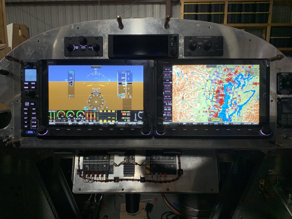
From that point, I started adding things back until I was powering both busses again, and I was able to get the entire Skyview system up and running. I configured all the network devices, got an initial hack at a display setup done, and generally just kind of sat there playing around with things. Lots of stuff isn’t going to be functional at this point – no GPS signal in the hangar, the engine monitoring obviously has nothing to monitor, and so on – but by god, it looks like airplane stuff.

The only rub here was the GPS-175, which didn’t want to power on. I reverified the connector pinout, made sure it had power/ground where appropriate, but still no joy. But when I connected the backshell to the GPS unit outside the rack, it powered up. Clearly there was a connection issue, but only in the rack.

Turns out that when I built this rack mount, I misunderstood how the mechanism for securing the unit in the rack works. I thought it was a simple locking tab, but it also has a threaded portion that mechanically pulls the unit into the rack. Well, even with the bezel of the GPS against the panel, the connector obviously wasn’t engaging. I’m pretty sure that, due to my misunderstanding of how the rack worked, I set it a bit too far back into the panel, so I’ll probably need to re-fabricate the angles that connect the rack to the panel.

I did go ahead and power up the GPS again outside the rack to try some configuration there. A nice VAF person sent me some information about getting the GPS properly talking to the Skyview units, and with his info, I got that setup done in under ten minutes; I was seeing message traffic from the GPS on the Skyview setup menu, and the GPS test mode was properly driving the Skyview HSI as expected.

So all in all a happy day. I guess now it’s about time to set all this aside and start thinking about working with the canopy. Only thing I still need to work out is routing the tail strobe wire out through the aft bulkhead, then I think I need to start getting the turtledeck permanently installed.

Posted in Avionics, Electrical, Fuselage | Hours Logged: 2.5

Tail strobe wire routing

Tonight I wanted to try and nail down the routing for the tail strobe wiring. I’ve been doing some reading and poking around at the best way to skin this cat for some time now, and in fact this is the sole reason I reinstalled the tail feathers a week or so ago. Basically, the question here is how best to pass this wire through the aft bulkheads and then down into the lower rudder fairing. I’d been leaning for some time towards going through both the fuselage bulkhead and the vertical stab spar above the lower rudder hinge point, and then routing the wire down towards the fairing. The idea was to have the movement of the rudder be taken up by a twisting motion on the wire, rather than having a repeated flexing situation.

Unfortunately, the more I looked at things, the tougher this seemed to be to pull off. For one thing, I’d have to go pretty far off-center to get around the hinge point, and for another this would mean routing the wire pretty close to the elevator control horns and push tube – which would in turn mean that carefully securing the wire would be more important – which in turn would be pretty tough to work out in the tight confines of the aftmost bay.

So after some more thinking, I had a new idea – what about having the wire exit the fuselage pretty low? Doing it this way, the wire would only pass through the fuselage and skip the stab spar entirely, which would be helpful for later service – if I needed to pull the stab, I wouldn’t have to pull the wire back out through the spar, potentially removing terminations. The question was how the routing would work after that.

While doing some more reading, I looked again at another builder’s approach and realized a genius to it I hadn’t picked up on before. By adding the bulkhead in the fairing, and putting the wire penetration point in line with the hinge line, the twisting of the wire would be minimized (or at least spread over a longer distance. And I decided I could combine this with my previous idea by adding an adel clamp, secured using one of the internal rudder stop bolts.

To test this idea, I mocked the setup using some scrap wire. Mainly I wanted to verify that I could keep the wire away from the lower rudder hinge bolt; that’s probably the most likely place for chafing back here. But with some careful bending of the wire this looked feasible:

 So that was my “go ahead and do this” point. There was a bit more consideration for locating the passthrough hole, since the tailspring socket is on the other side of the bulkhead, but I worked out a good location and got the hole drilled. Next was putting another passthrough hole in the next bulkhead forward – in this case I decided to locate the hole more along the aircraft centerline. My reasoning here was that the wire needed to go from above to below the lower longeron, and I wanted to not have the wire rubbing against that edge. So this routing would keep it further away, and I decided to also protect the wire in this area by feeding it through some silicon tubing I had on hand.

So now, aft of the F-810 bulkhead, the strobe wire separates from the pitch trim wire it’s run with, angles down and towards centerline, and passes through a small snap bushing in the bulkhead ahead of the control horn bay:

Then, in the next bay, it’s covered in the silicone tubing and moves further down and back outboard. As a side note, after getting the silicon tubing in place, which was a bit of a challenge (it’s a snug fit), this run actually doesn’t get anywhere near the longeron. Oh well:

 Finally, the wire exists the last bulkhead through another snap bushing, where it will eventually get routed as seen in the first photo. In the meantime, the tail feathers are back off again, because drilling that forward hole would have been impossible with them in place. Hence why the stab is missing again in this final photo:

 So this is getting me pretty close to having the tail cone ready to close out. The pitch trim wiring will just route out of the hole in the aft deck and over the horizontal stab spars, so nothing more really needs to be done on those right now. I did go ahead and secure the tail wire to the pads I put in place a while back, so that’s squared away now:

So I think really the only thing left to do is to route the pitot and AoA lines through the seat floor conduit and back to the area of the ADAHRS mount. Then I guess I’ll need to bring down the turtledeck skin for the last time and get it ready for riveting. I’ll still have to pull some stuff from the tail though, like the ADAHRS mount and the aft avionics shelf, but that’s all pretty straightforward. But I guess I’m not too far from the joy of some fun tight-quarters riveting.

Posted in Electrical, Fuselage | Hours Logged: 2

Finished verifying tail wiring

As mentioned before, my current goal is to verify as much internal tail stuff as possible before I get down to permanently attaching the turtledeck skin, since that will turn any work behind the rear seat into a sort of cave diving expedition.

First up, I figured I’d see if the tail strobe wiring was OK. I didn’t really have any reason to suspect issues – compared to the wiring for the avionics stuff in the tail, this is dirt simple – but it doesn’t hurt to check. Plus it’s just fun to flip switches and make things happen, especially if I can then go walk out to the end of the ramp and say to myself, “yeah, I should be pretty visible to other aircraft.”

Next up was the more fun thing – trying to get a GPS fix out of the GPS-175 so I could verify it was sending position data to dependent components, specifically the transponder and ELT. At first I was intending to figure out a way to move the entire fuselage out of the hangar to get a clear view of the sky, but I couldn’t figure a method of moving that 1) I trusted to not potentially go wrong and cause damage and 2) wasn’t way too much work for a one-time verification task.

Instead, I worked out an alternative method – move the fuselage as close to the open doors as possible (much simpler than moving it out since I didn’t have to deal with bumping over the concrete lip and hangar door tracks), and then put the actual GPS antenna as far as the cable would allow. Since Garmin requires a minimum cable loss, which in turn means a minimum cable length of 6.5’, this was pretty doable. With this setup, the antenna had a clear view of a little more than half the sky, which I was hoping would be enough for a solid fix – and it was.

So then I went into the Skyview setup menu and went to look at the transponder page, which would tell me if it was getting position data from the GPS-175. Everything was indeed kosher, and the system now believes it is ADS-B Out compliant (this means the transponder can transmit position data accurate enough to meet legal requirements):

That just left the ELT. Here, I had to do some documentation mining – the Artex 345 I have says that it accepts aviation format serial data at 9600 baud, whereas the GPS-175’s serial setup options offer both “Aviation 1” and “Aviation 2,” with no mention whatsoever of baud rate. The Garmin manual provided no clarification I could find, nor did my Google search attempts yield anything, so eventually I decided I’d just pick one format, try it out, and see if it worked – if not, I’d try the other one.

The fun part here is that unlike all the other stuff I’m playing with, the ELT provides no sort of user-friendly UI to get setup info. The only way to check for setup issues is to have the unit run a self-test and see if it reports problems – which it does by blinking the LED on the remote panel switch. Kinda reminded me of checking trouble codes in OBD I cars, where you had to count how many times the check engine light blinked at you.

I was a little surprised that I got no error codes on the first self-test, which seemed too good to be true. So I did a typical software troubleshooting move by intentionally causing the error condition – in this case, powering down the GPS-175 so that the ELT ought to report no position data – and that did indeed get me the error I expected. GPS back on, one more self-test, and once again no errors.

Oh, and I don’t recall if I mentioned it before, but while testing and tinkering with the EFIS, I’ve seen some other aircraft show up as nearby traffic, which confirms that the ADS-B receiver back in the tail is doing its job correctly. So at this point I’m pretty confident that all the tail wiring is in good shape. The only thing I haven’t tested is the elevator trim motor, because I think rigging up a test with that will be more trouble than it’s worth.

So…I guess its really time to pull that turtledeck skin down, finish prepping it (I know it needs to be dimpled, pretty sure I haven’t done any demurring yet either), and get that thing riveted on. Which will unfortunately mean spending one time lying inside a really snug cave in the summer Houston heat, but such is life.

Posted in Avionics, Electrical, Fuselage | Hours Logged: 1.5

Canopy rails, misc systems stuff

I picked up this morning with work on the center canopy rail I started on a few days ago. I got all the rivet and screw holes laid out along the rail cap piece, which is what’s used as a guide for all the drilling. As mentioned before, it took me a bit to figure out the plans here, but the gist is that there are eight screw holes a specified distance apart, and between each pair of screw holes are five rivet holes, which make the spacer and cap into a single T-shaped piece.

So I started out by marking the screw hole locations and drilling them initially to #40. That let me cleco the rivet fane between each pair of holes and center punch the rivet holes in between. With that done, I clamped the spacer onto the cap and drilled the screw holes up to #30. This was where the first thing went wrong for the day; since it takes a bit to get the drill through that thick spacer piece, I wasn’t really good at anticipating when the drill would break through, and once I had a few holes in the wood block I was backing the work with…well, on one hole the bit broke through and barely even slowed down, and so I ended up making a nice little circular scratch with the drill chuck:
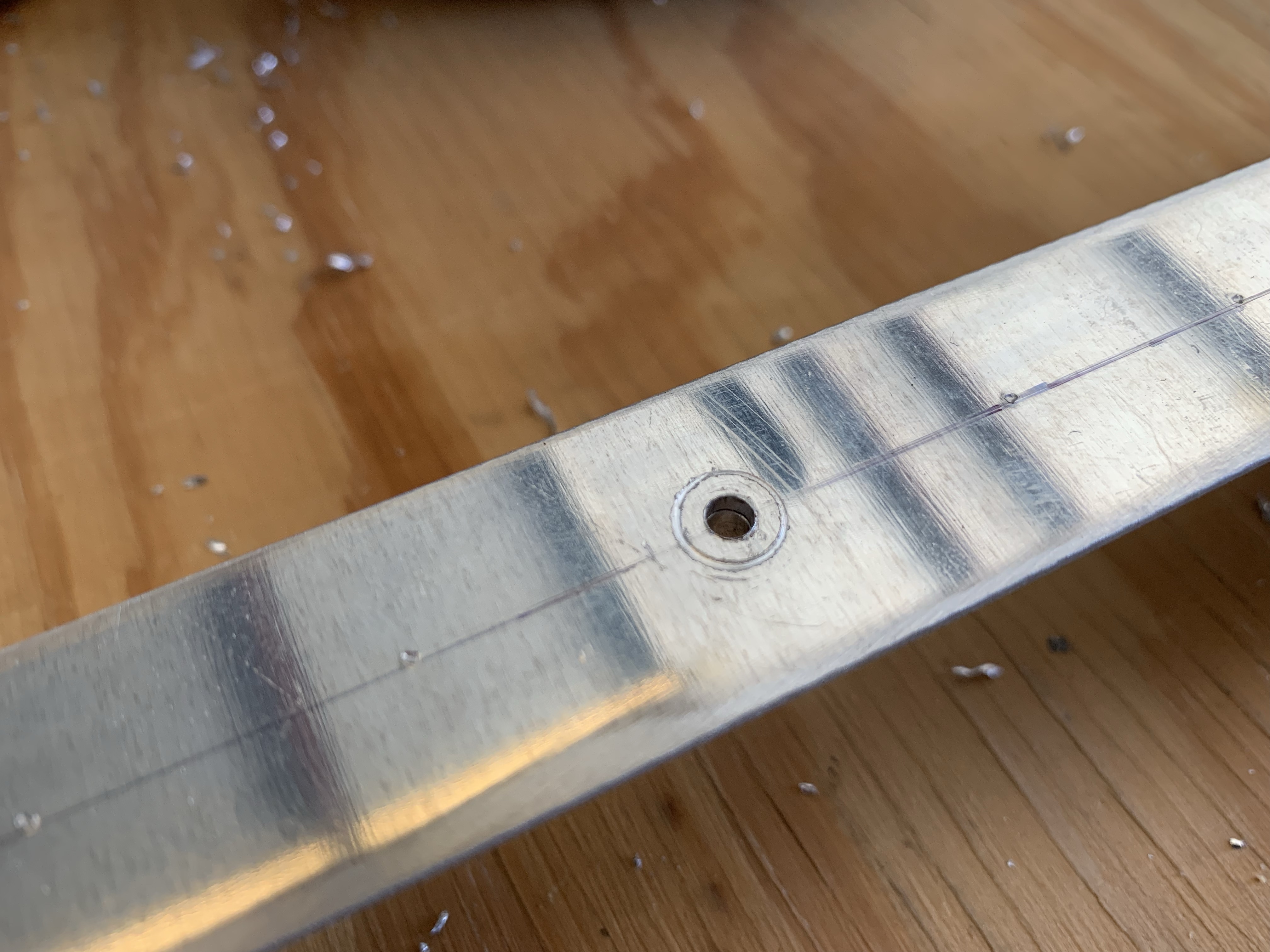
This was bothersome to me, since this is going to be a very visible part of the airplane that also likely won’t be painted…so there are limited options for getting rid of this ugliness. Now, this hole will eventually be countersunk for a #6 screw, but the screw head is still smaller than the scratch, so that wouldn’t help. I came up with the idea of maybe upsizing to a #8 screw, and to test if that would actually cover the scratch, I intentionally marred a piece of scrap and then worked on countersinking it, and found that I could cover the scratch if I was liberal with the countersink, putting the screw head just below flush.

So with that in mind, I kept going, moving on to drilling the rivet holes in the assembly. Everything seemed to be going well until I separated the parts for deburring and eventual countersinking, and found that the other side of those rivet holes were…let’s say inconsistent. Apparently my attempts to hold the drill bit square to the rail cap failed pretty miserably, and I drilled the holes in various states of crookedness. Still, the visible part looked OK, so I thought maybe the slightly off holes might be OK…until I tried countersinking them, at which point it was obvious they were crooked enough to cause problems with the countersink cage.

At that point, I decided it was settled that these parts were officially junk. Fortunately, the replacement cost isn’t bad at all – under $20 for the parts from Van’s – but I’m sure the shipping will be a bit interesting since both pieces are about 4’ long. Oh well, that’s the way things go.

Before ordering, it seemed prudent to look at the other two rails, just in case I fouled those up too. At least then I could combine the shipping cost for the parts. These are the two rails that sit on either side of the canopy, and they’re made of some C-channel type extrusions. Interestingly, the back end of each channel is precut at an angle to match the bulkhead behind the rear seats, but the rails still need to be trimmed at the front end. Marking these was a little interesting since they’re not a nice square cross-section, but trimming them wasn’t a big deal.

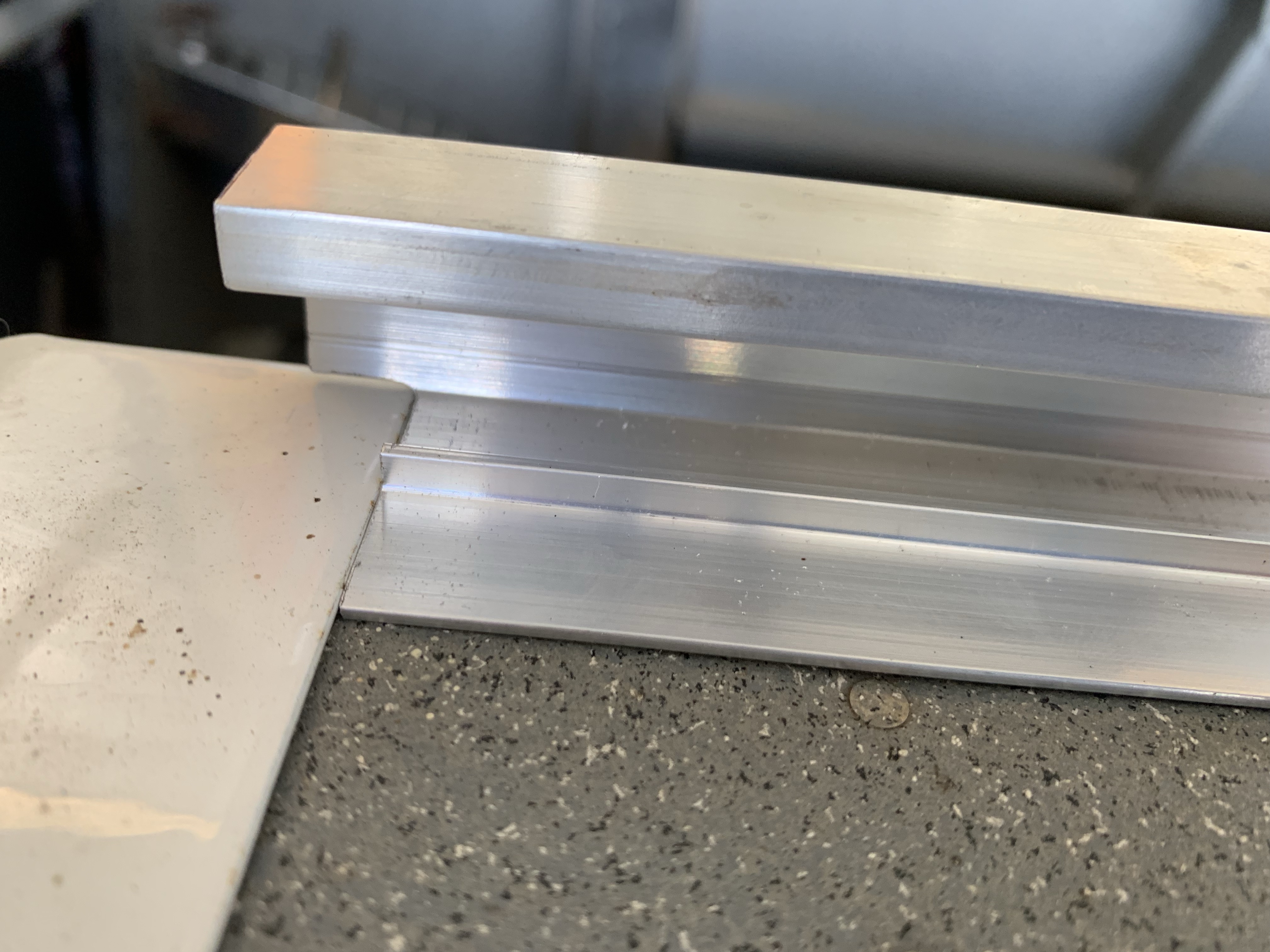
The more interesting part is that the forward end of the rails overlaps with the roll bar base, so the bottom forward corner of each rail needs to be relieved so it can sit flush elsewhere. This just required some careful rough cutting with the band saw and dremel cutting dock, followed by fine-tuning everything with files. In the end, I got a nice tight fit with the base:
Unfortunately, that’s all I can do with the canopy right now. Next steps would be to install the center rail on the fuselage and clamp these side rails into place, then start working on fitting the canopy frame, but…yup, no center rail for me. So I ended up crawling back inside the fuselage to reassemble some stuff I removed for riveting clearance. First up was reattaching the wire bundle in the aft most bay; I had to remove the the zip ties holding to the pad mounts to have clearance for bucking rivets. Was definitely a lot of fun getting my arms back in there; well actually, I could only get one arm in for aft pad. Turns out starting a zip tie one-handed is an interesting challenge.

Next was permanently installing the ADAHRS mount. This is attached to the longerons with blind rivets, because there’s simply no way to get a rivet gun back in here. I guess screws would have been an option as well, but I don’t really intend for the entire mount to ever be removed, except in the case of a major systems overhaul way down the road. A side note here: the little “pop” you get when the stem breaks on a blind rivet is a whole lot louder when it happens inside an aluminum cone.

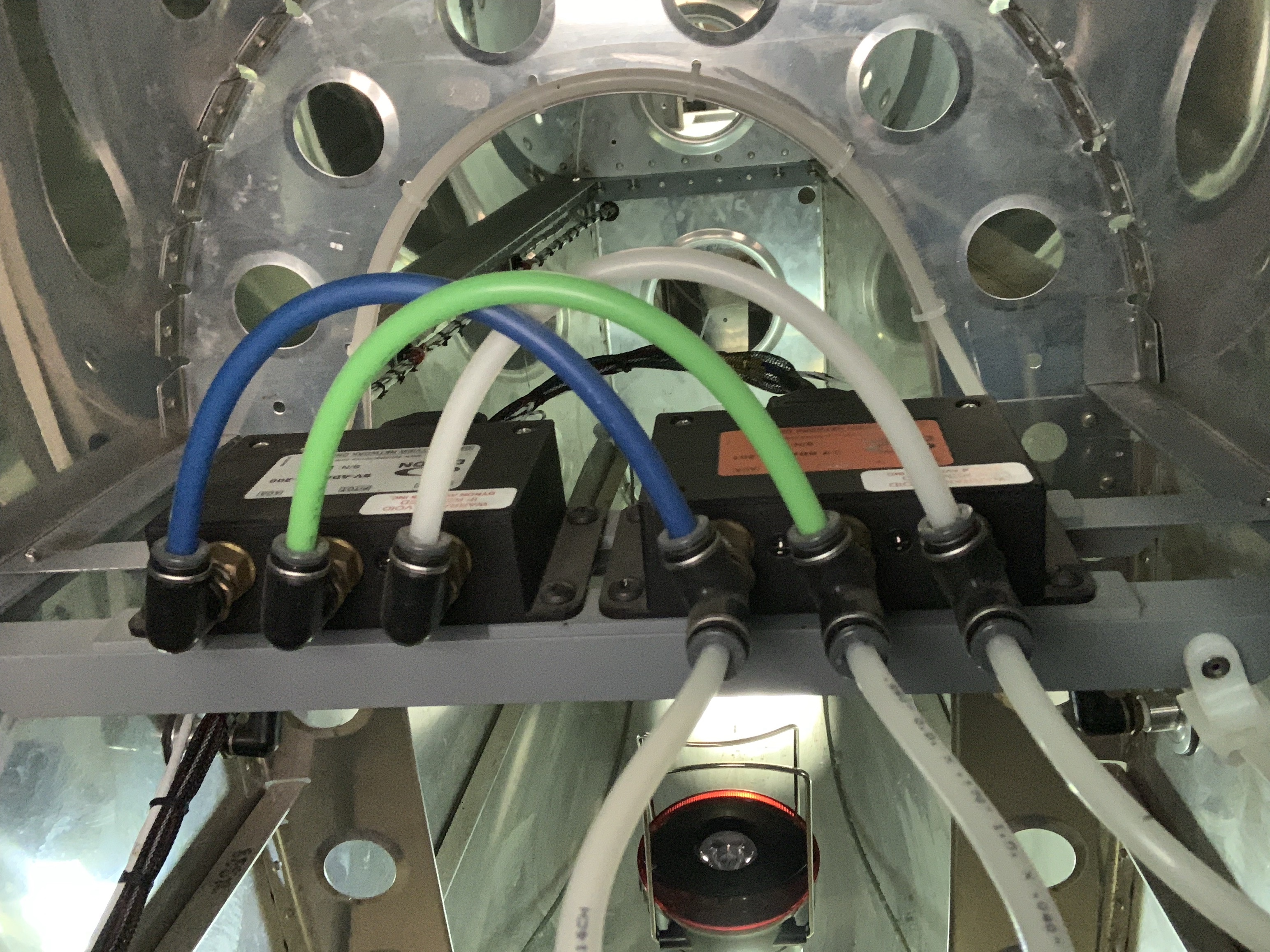
But hey, with the network/OAT connectors…reconnected…along with the static line, these are pretty mush ready to go. Only thing remaining will be routing the pitot and AOA lines back here at some point. Original plan here was to run them uninterrupted from the wingtip, though I’m kind of considering putting in disconnects inside the fuselage at the wing root, simply so I can go ahead and get the lines routed back here. I’m pretty on the fence about that.

Oh yeah, look, a photo:
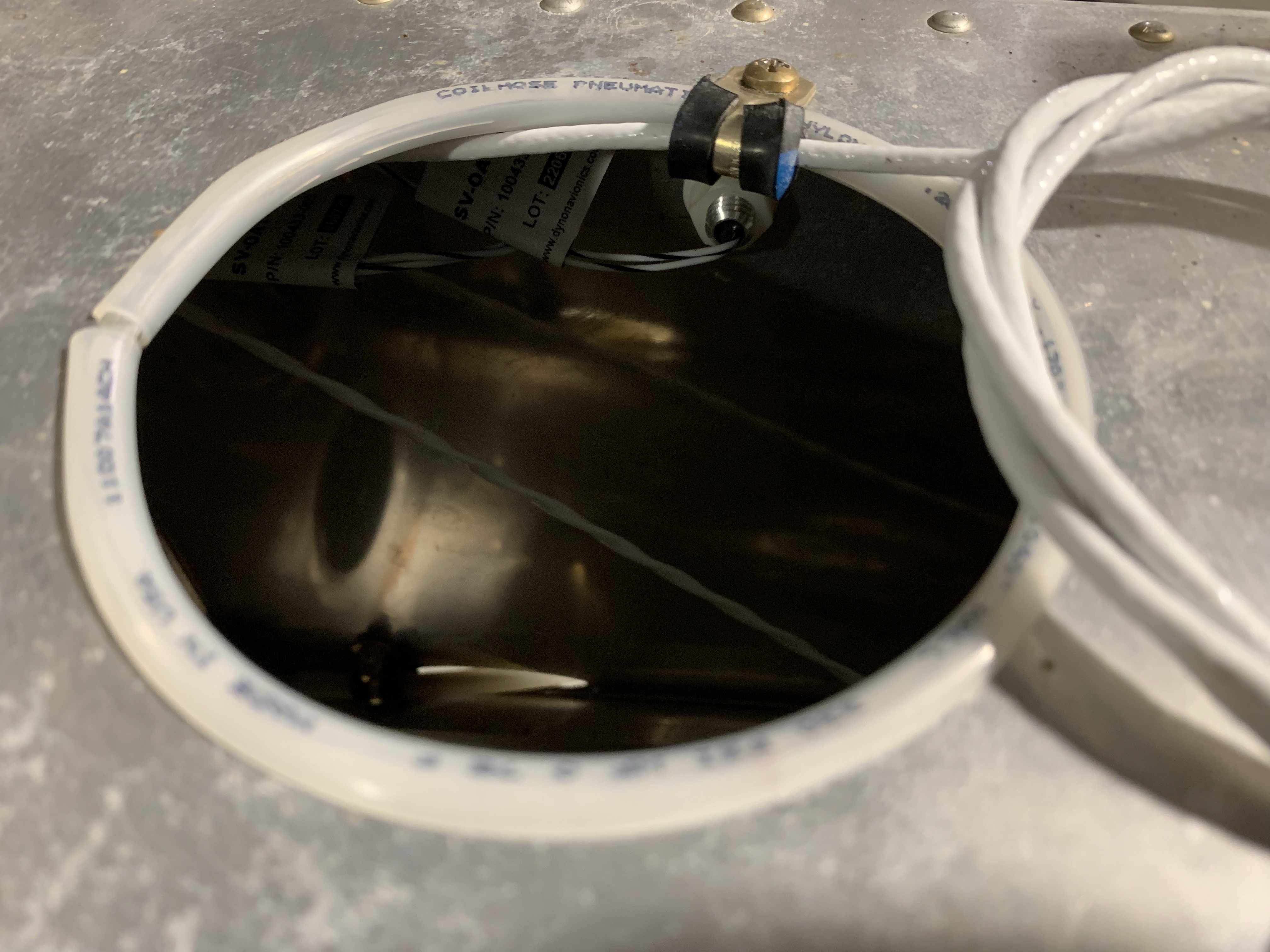
Finally, for one more random systems thing, I took care of some routing for the elevator trim cable. This will come up through the aft deck lightening/access hole; I went with the same anti-chafe setup I’ve done elsewhere, just taking some of my surplus static line, splitting it, and slipping it over the edge of the hole. Then I added an adel clamp to hold the wire in place where it passes through the hole:
Now I just have to figure out what to work on while I wait for parts. Kind of thinking I may go ahead and mount the empennage again, this time for what might be the last time – though I should be careful making pronouncements like that. With the empennage in place I could go ahead and finalize the wire routing and disconnects for the elevator trim servo. I could work on the tail light wiring as well, though that would require getting my hands dirty with the fiberglass rudder fairing.

The other complicating factor is that we’re two weeks out from heading out on a three-week road trip. I’d been hoping to make some good progress on the canopy before then, but it seems unlikely that’s going to happen – I imagine the last week pre-trip isn’t going to be super productive on the airplane. Hopefully I can at least get the replacement rail parts in, and get the center rail in place for future fitting. If I can get the canopy trimming done by the end of October or so, it should still be decently warm during the days, keeping potential cracking as a smaller concern.

Posted in Canopy, Electrical, Fuselage | Hours Logged: 3.5

Pitch trim wire routing

Well, so far there’s been no ship notification for the replacement canopy rail parts I ordered on Monday, which may very well mean that I won’t have those on hand before we head off for our road trip. Meanwhile, I found some time in between trip prep to do a little more work, this time on the pitch trim servo wire routing.

First step was to get the horizontal stab back in place. This was way more fun than it should have been; having that turtledeck skin in place makes attaching the stab way more interesting. Despite my best attempts, I couldn’t figure any way to reach inside and put any of the attach bolts in place from inside. I guess this is just going to require the services of someone really small – it’s going to require going even further into the tail than I went while riveting. I made do for now by just dropping the bolts in place from above to at least sort of hold the stab in place while I worked. One thing I want to figure out is whether or not it’d be sensible to go ahead and final-attach the stab, though it’s not a critical decision at all.

Next up was working the actual wire routing. I decided to add another adel clamp on one of the stab attach bolts to guide the wire up and over the rear stab spar. From there it’ll be attached to the elevator control horn tube, which will of course move with the elevator itself. I added a small snap bushing to the inboard elevator rib for the wire to go inside and connect to the actual trim servo:

Actual connection to the servo will be done by way of bare D-sub pins (ie not inserted into a connector). By using these, and staggering the wire lengths, the result is a nice and compact connection that’s also watertight (the whole thing will be covered by heat shrink). I’d fully intended to get these terminations done tonight, but after a lot of thinking and visiting schematics and thinking about how the trim works, I’ve decided to wait until I can actually test the trim system.

The reason for this is that since I’m staggering the wire lengths, it won’t be easy to switch the two trim wires if I get the polarity wrong, and after all that reading mentioned above, I don’t feel super confident in my ability to reason out which wire goes where. There’s no real reason not to wait until more stuff is wired up to do this, either; it just cost me a little bit of satisfaction tonight.

Posted in Electrical, Fuselage | Hours Logged: 1.5

Finishing with the engine mount, doing some wire routing

As I headed out into the hangar to get to work this evening, it occurred to me that I hadn’t had a single super bright idea about how to stretch out this engine mount to get the second pair of holes drilled. All that random thinking about making a jig with threaded rod and so forth hadn’t gone anywhere concrete. So I ended up just trying to stare at things and work out a solution, and eventually I got to something.

Basically, there are two ways to approach this: either I need something inside the mount exerting outward force to spread things, or I need something pulling down on the bottom of the mount. The latter seemed impossible since I had nothing to pull against, but finally I realized that if I stopped thinking in terms of using something like a ratchet strap, there were other ways to approach this. What if I could just hang weights off the bottom of the mount and try to work with the positioning that way?

And that’s how I ended up with this amusing Rube Goldberg setup:

We’ve got a 30-pound kettlebell hanging on the center of the mount, using an S-hook normally reserved for hanging up a caliper while working on the car brakes, plus another 30 pounds of dumbbells lashed together with some spare paracord and hung from the corner with more spare paracord. The only real issue with the hanging-weight idea is that you don’t have a lot of fine control over how much the mount stretches, and that’s where the big clamp comes in. Hanging the weights as shown here got the hole just a tiny bit above where it needed to go, so with the clamp in place, I could carefully apply that last bit of force to get it all lined up nicely.

The only remaining issue was how to pull the mount snug against the firewall while doing this; as it sat, the mount face wanted to sit about 1/4” off the firewall. I initially tried using a ratchet strap secured to a long piece of lumber going through the center section, but the strap would have been bearing on the edges of the forward side skins and the firewall flange, and surely would have bent something if I’d started cranking down. Then I had another epiphany – the other lower hole could be used for this. I just had to run a 3/16” bolt through the hole and the mount, add a large washer so it’d bear against the mount hole, and tighten the whole thing down.

That pulled both lower holes up nice and snug, and once I had the lower right hole drilled and bolted, the other was already lined up nicely and didn’t even need any drama to get it set up. The only concern here is how annoying it’ll be to attach this mount unless I permanently stretch it, so I’ll probably have a go at that at some point, but not tonight.

Instead I decided to continue thinking about FWF type stuff. One item I’ve been putting off for a while is drilling the 3/4” hole down the right side of the aircraft for all the engine sensor wires and such to pass through. That seemed like a nice digestible project for tonight, so I got to it. I’d been thinking that laying the hole out properly would be a challenge, but once I got down to it it wasn’t tough at all. The only hiccup I had was that the unibit drifted a bit as I was opening the hole, and got into the edge of one of the firewall angles, so I had to then go in with the dremel and sanding drum to smooth things out.

Once that was done, I installed the snap bushing and had the fun of feeding the wire bundle through from inside, and now I’ve reached the milestone of having random wires sticking out through the firewall:

Assuming I don’t get that replacement canopy block in sometime soon, I think I might start marking up the firewall for component locations, just to sort of spitball ideas. The FWF plans include some suggested layouts that I’ll likely start with, but I’ll have to consider some other items not shown there that I’m adding – like the battery-bus fuse block and E-bus relay. Those are pretty small but they still need homes, and routing of wiring is also a concern.

The other item I could work on now would be feeding the CPI2 FWF harnesses back through the firewall and finishing up the lacing of the relevant harnesses in the cabin. Those had to wait until now, as they’re already terminated no the engine side and so can’t be fed through in the other direction. It’d be kinda nice to finish up those harnesses inside, I suppose. We’ll see.

Posted in Electrical, Firewall Forward | Hours Logged: 2