Started riveting right wing skeleton

Popped out into the garage tonight figuring I could get going with the right wing skeleton. First I had to cleco all those ribs to the main spar, which was fairly straightforward…until I got to one rib that seemed off. Oh, that’s because I drilled the mount holes for the wiring conduit on the wrong side of the lightening hole. Well, good thing I still had the little jig I made sitting around. Two more holes and all was well.

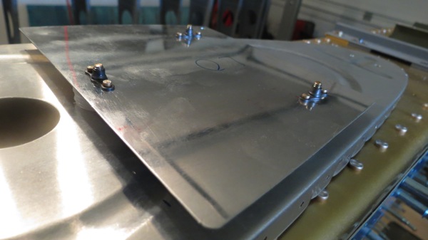
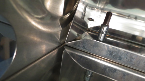
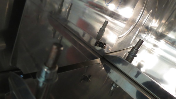
I started with the inboard wing walk ribs. The first one went nicely, and the second one seemed to be going OK, but while examining the manufactured heads I noticed one seemed out of alignment with the others. Upon closer investigation, I somehow managed to really smear the head badly.

IMG 2064

IMG 2065

So now I need to replace that rivet. Problem is, when drilling a rivet out, you use a dimple on the manufactured head as a center punch to get started. Well, that’s not much good when the manufactured head is fouled up like this. I posted some photos to the brain trust at VAF to get some suggestions on how to drill this thing out. I’m not much looking forward to it, since these long rivets grip a lot and require a lot of force to dislodge.

Anyway, I called it a night there. No need to push on and maybe mess up more stuff while I’m distracted and a little miffed by the mistake.

Posted in Wings | Hours Logged: 1

Primed right wing main ribs

Well, this hasn’t been a particularly productive weekend in terms of hours worked, but getting these wing ribs primed removes a fairly significant bottleneck for me. I’ve been hesitant to keep working on the left wing for the tim being; I’d prefer to be able to perform tasks on both wings pretty close together, to cut down on “how did I do this before?” moments. Plus, since I match-drilled the right wing, the right main spar has been sitting on my workbench, cause I don’t really have any other good place to store it. Hence why I’ve been focusing on gabbing up parts for both tanks recently.

Anyway, today I didn’t get to work until the afternoon, but i got the ribs scrubbed , dried, and primed. After some touch-up work, they’re now stacked int he garage where they can dry tonight and tomorrow. Hopefully tomorrow I can get to working on riveting the right skeleton together. No photos today…

Posted in Wings | Hours Logged: 4

Tank attach angles

Well, we had quite a day out here. We decided to run down to the beach with dogs and make a half-day or so out of it. Unfortunately, things got interesting on the way home – the car overheated. Seems I have a bit of a cooling system leak somewhere. I managed to make it home without any more overheating, but at the cost of driving with the heater running full blast. In the Houston summer heat. Actually, it wasn’t that bad on the highway, except for my feet getting thoroughly cooked. I now know that this car’s heater is tremendously effective.

Anyway, by the time we got home, I was tired again and I took a nap. Then it was finally out to the garage, where I got to work on the T-405 tank attach angles. I’m glad I decided not to try to do these last night; they weren’t terribly difficult, but there was a lot of time-consuming “how should I do this…” along the way. If I’d put some time pressure on myself to finish it last night, I might well have messed something up.

First, the chunk of angle gets cut to the rough length of the attach piece:

IMG 2057

One side gets a symmetrical round profile, while the other is shaped to fit inside the nose of the inboard tank rib. I used one of the reinforcement plates as a pattern for this. Here’s the cut line I made on the first angle:

IMG 2058

Roughly cut to size in the bandsaw. I did a fair amount of vixen file work to fine-tune the shape, but I can’t remember if this photo is before or after I did that:

IMG 2059

Then it’s over to the bench grinder to remove all those nasty tooling marks and make all the corners nice and smooth:

IMG 2060

The second angle went a lot quicker, mainly because I could just use the first one as a pattern instead of having to carefully lay out cut lines. Here’s the pair:

IMG 2061

These will eventually get drilled to the tank ribs, but that will wait until I can get the right wing caught up with the left. Weather tomorrow looks good, so provided my local Napa has a good stock of 7220 primer, I can finally get those right wing ribs primed and then work on riveting that skeleton together.

I also took some time tonight and read through the instructions for the capacitive fuel sender kit. I can see that these tanks are going to take some time; there are lots of little details that have to be attended to. Fuel senders, access holes, vent lines, caps, drains…fun times!

Posted in Fuel Tanks, Wings | Hours Logged: 2.5

Tank stiffeners

So I had a good little mini-vacation this past weekend. I even got in a little flying while I was in Raleigh, doing an Arrow checkout up there. I’d hoped to be able to take my niece up for a flight, but unfortunately the weather on Monday and Tuesday wasn’t agreeable. While I was gone, my shipment from Van’s came in, in a nice wooden crate, which Josie got to manhandle into the house by herself (sorry babe). Wednesday night, I moved the crate into the garage, opened it, put everything away, and then tore the crate down. Hooray, more scrap wood! Then I took the rest of that night and last night off.

Tonight I decided to make all the tank stiffeners. These will be attached to the bottom skin between the ribs to provide, well, stiffness. After all, each of these tanks will hold 21 gallons of fuel, which weighs 126 pounds! The stiffeners come prepunched, but they’re also attached together into long strips that have to be cut to size using notches for reference. I finally learned my lesson here after making stiffeners for the tail: I removed the blue film before I cut the stiffeners to size. Much easier to remove the film from four long pieces than from 48 short pieces.

After a lot of work with the snips and a sore right hand, I had a pile of scrap pieces and a larger pile of very rough-edged stiffeners:

IMG 2052

IMG 2051

Then it was time to spin up the bench grinder to clean up the edges. I gave that grinder a workout tonight – I probably ran it for about 40 minutes straight. When I was done, I had a bunch of nice smooth stiffeners:

IMG 2053

I was about 90 minutes into the evening at this point, but I didn’t quite feel like quitting, so I decided to look at fabricating the T-405 inboard tank attach angles. These get fabricated from raw angle and attach to the nose of the inboard rib on each tank. There’s also a reinforcement plate that goes on the inside nose of the inboard and outboard ribs on each tank. Since the attach angles are made to fit the contour of the nose rib, it seemed like a good idea to clean up the reinforcement plates first to use as a guide/pattern. So I broke them out, removed the film, and fired up the bench grinder yet again to take the corners and tooling marks off. Very nice:

IMG 2056

From here, I found the piece of raw angle that the T-405s are fabricated from. I briefly considered getting started on them, but it was getting late by this point, and I was a little worried about cutting corners if I decided to try and make them tonight. So I went inside instead; I’ll probably do the attach angles tomorrow. Actually, now that I look at the weather, tomorrow looks clear. If I can restock on primer tomorrow morning, I should take advantage of the good weather and get the right wing ribs primed. Maybe I can get the right wing skeleton riveted this weekend too. Right now the right main spar is living on the workbench because I don’t have a good place to store it. It’d be nice to have that whole workbench back…

Posted in Fuel Tanks, Wings | Hours Logged: 2

Right wing rib deburring

Just did a short stint in the garage tonight. My main goal right now is to get the right wing ribs to a point where I can prime them the next chance I have. So tonight I pulled the right skeleton apart, deburred everything, and undertook the tedious task of peeling off the little stickers that identify the parts. But now when I have a good weekend day, all I have to do is take them out back, clean them, and prime away.

I guess from here I’ll work on some of the small items for the tanks; some of those I can work on before the right tank is together, like the nose rib reinforcements and so forth (actually, the stiffeners would be a good target item here too). I also got a ship notification from Van’s today, so either late this week or early next week I should have my replacement skins and other stuff.

Also, a side note: I’ve been kind of dreading the upcoming messy task of sealing the tanks. A couple nights ago, a ran across a discussion on VAF about working with sealant. Rick, who apparently has worked on some big military projects, has some sealing techniques that are different from the Van’s instructions, but sound much less painful and messy. I’m glad I found that discussion, because I intend to use those techniques, and hopefully I won’t end up hating ProSeal as much as most people.

Posted in Wings | Hours Logged: 1

Fitting left tank, right wing skeleton drilling

So when we left off yesterday, I’d victoriously dropped the fuel tank onto the spar, only to find that the joint plate was too wide. As such, the first order of business today was to fix that. First off, I measured the gap with the tank slid as far outboard as possible; this way I could tell what the minimum amount of material to remove would be. Turned out to be a hair over 1/8”. After removing the tank and measuring the exposed joint plate, it turned out that I needed to remove enough material to leave 11/16” of an inch showing. Which is – surprise! – exactly what the instructions said in the first place. Though, in my defense, the wording was something like “there should be 11/16” instead of “make sure there is exactly 11/6”.

Whatever. So I went ahead and marked a cut line all the way around the plate:

IMG 2032

I’d spent a bit of time mulling over the best way to make this cut, and I eventually settled on just using the snips. The downside of the snips is that they leave a rough surface that needs a fair amount of cleanup, but about the only other method I could think of was to use a Dremel cutoff wheel, which is just annoying and imprecise. So I pulled the plate off and went to town with the snips.

it was a long and tedious process; the plate, after all, is something like four feet long, and with it being curved, that just adds to the fun. By the time I finished the cut, my hand felt on the verge of cramping. Now I had a nasty rough edge, so I broke out the vixen file and went to work. This, too, proved to be difficult, as there wasn’t much of a good way to clamp the curved plate, so I ended up just holding it in one had while I filed. If this sounds iffy, good call. In the course of the filing, I learned that a vixen file will remove skin just as effectively as it will remove aluminum.

Finally, I had the thing cleaned up, and I finished it off in the bench grinder for a nice edge. All told the cutting, filing, and general cleanup took me almost an hour.

So I put the plate back in place, put the tank back on, and all was well. Now the tank sits nice and tight against the leading edge:

IMG 2034

With that done, it was time to drill the tank attach brackets. With the tank slid over in place, I put a couple of ratchet straps around the wing to hold the tank nice and snug:

IMG 2033

The inboard bracket is drilled first, because, well, it’s the only one visible. These holes are kind of nerve-racking to drill, what with the spar right under them. I used a drill stop for all these holes, and I checked the thing about every five holes to make sure it wasn’t coming loose. Soon, the inboard bracket was drilled:

IMG 2036

Next, the leading edge assembly comes off to reveal the outboard bracket, which can then be drilled:

IMG 2037

And finally, the clecos between the tank skin and the baffle and outboard ribs are removed, allowing the interior brackets to be drilled in place:

IMG 2038

Since I don’t really have anywhere to store the leading edge and tank assemblies, I just put them back on the spar for now. Then, I decided it was high time I got to working on the right wing, so I clecoed the right skeleton together and got it all match drilled. About this time, dinner showed up, so I decided to call it a night.

I’ll be out of town next weekend, so I guess the next opportunity to get the right ribs primed will be two weeks away. I suppose I’ll get them deburred this week so they’ll be ready to go when I get some good priming weather. In the meantime, I can work on some of the common tank pieces – there are a number of things to fab up, like stiffeners, mount plates, fuel lines, level sensors…yeah, no shortage of things to do.

Posted in Fuel Tanks, Wings | Hours Logged: 5

Left tank attach brackets, tank fitting

Technically, I did a little work last night, but not enough to merit writing an entry. All I did was go out and finish stapling the carpet onto my C-frame table thingy, which took maybe half an hour. I also placed a nice-size order with Van’s on Friday: replacements for my damaged skins, replacement tank brackets (plus a few extra for good measure), tank sealant, and a few other sundries.

Today, I set out to redeem my bracket mangling from out last outing. First up was to drill the inboard bracket (for the third time). This time I got the center hole where it was supposed to be, squared the bracket to the spar, and drilled the other two holes. Nothing to it when you actually use a good sharp drill bit:

IMG 2023

Next up I drilled the center bolt hole in the other six brackets for this wing. To help to this in a consistent fashion, I only measured the first bracket before drilling, and then I set up a little arrangement on the drill press table so I could quickly drill the other five brackets:

IMG 2025

I’m leaving this in place for when I get the replacement brackets next week; at that time, I’ll go ahead and drill the six outboard brackets for the right wing as well. Might as well go ahead and get them done, even if that skeleton isn’t together yet.

From there, I went down the spar, bolting each bracket in place and drilling it using the spar holes as a guide. The work went fairly quickly, although it left a large amount of metal shavings in my previously spotless wings:

IMG 2026

Oh well, that’s what the shop vac is for. Next, the outboard brackets get drilled for nutplates. There are nice little jigs out there for drilling nutplate mounting holes, and I hear they’re nice, but honestly, I didn’t find it to be too tedious at all to just use the nutplates as my patterns. I picked out three nutplates to be sacrificial, since I’d be bolting/unbolting them many times. This let me set up each bracket and drill all its holes in quick succession:

IMG 2027

Next I gave all the brackets a good deburring, both the holes and edges (the edges were pretty rough). Then I countersunk the opposite face for the flush rivets, since this side will sit against the spar. Finally, it was out to the back yard for a good cleaning and priming. I masked off the bracket face that will attach to the tank baffle; this will get a coat of sealant, so the primer would be counterproductive to getting a good seal there.

Here are all the primed brackets in place, ready to be bolted on for tank fitting:

IMG 2029

Now it was time to cleco the tank assembly together. This was a real chore; the leading edge is tough to get together, but the tank skin and ribs are made of thicker material, and it takes a fair amount of force to get some of this stuff into alignment. Oh, and I ran out of silver clecos while doing this, and had to kind of ration the things to get everything together. Guess it’s time to order some more.

But finally, it was all together and it was time to set it on the spar and see how everything fit. And it’s hard not to cackle when you see this sitting in your garage:

IMG 2030

Except there was one problem. Back when I was doing the leading edge joint plate, I found that I had more plate sticking out than expected, and I was worried about it interfering with the tank rib, so I moved it outboard a bit before drilling. The good news is that my concerns were well-founded. The bad news is that I still have an interference problem. This is as far outboard as the tank will go before the rib makes contact with the joint plate:

IMG 2031

So I’m going to have to trim that joint plate now, which will be a bit of a pain. Since the plate is bent, I can’t just run it through the band saw. I guess I’ll probably have to remove it, draw a guide line, and trim the thing with my snips.

I’m kind of glad I’ve held off on the right wing skeleton. On the one hand, if I was doing these tasks on both wings simultaneously, I could probably go a little faster by combining tasks. But on the other hand, I’d be making mistakes like this twice. Now, when I do the right wing joint plate, I’ll know better than to fudge the specs.

Posted in Fuel Tanks, Wings | Hours Logged: 7

Tank attach angles, C-frame fixture

First order of business today was simple: drilling the skin hole for the tiedown attach to full size. I actually skipped a step a while back that’s relevant here; the plans tell you to draw a couple of lines on the bottom skin that intersect at the center of the tiedown attach bracket. Then, when you set the leading edge in place, you’re supposed to use those lines to determine if the prepunched hole in the leading edge is located correctly. Well, I forgot about those lines until I’d already pulled the bottom skins off. Whoops.
But it’s actually pretty easy to check the location of that hoe otherwise. First off, there’s a gap between the skin and the attach, so you can see in there a bit; it appeared that things were aligned OK. To double-check this even more, I found an Allen wrench that fit in the skin hole, inserted it, and angled it until it hit the edge if the hole in the attach bracket. In this way, I could look at the angle and pretty effectively determine if things were OK, and they were. Si I busted out the Unibit and drilled the hole up to 3/8”. I don’t have the tiedown eyes, but I screwed in a carriage bolt to check the fit, and it looks great:
IMG 2018
Then it was on to the tanks. Now, somehow I got the idea in my mind that tonight I’d be setting the temporarily assembled tank on the spar and looking at a whole wing-shaped object. That was…a bit optimistic. There’s a good bit of work that has to be done on the tank attach angles first. I dove in headfirst with the inboard angle. This one is different from all the others in that the bolts go in from the forward side and screw into nutplates riveted to the spar, wheres the other angles have nutplates riveted to them, and the bolts go in from the back side. I started with the inboard one because this is where I riveted those nutplates ahead of schedule, and I wanted to go ahead and find out if that was a mistake.
First, I laid out the spot for the center bolt (of three) and drilled it to full size on the drill press. Then I bolted the angle in place and squared it against the spar bars. Since I’d be using the nutplates as a guide, I’d have to drill the other two holes undersize at first and then enlarge them in the drill press. The first problem was picking the right bit. #30 was kind of small, and didn’t fit the nutplate very well; not good for precision. #19 was too big. So I busted out my cheap drill bit set (MISTAKE) and went with a 5/32” bit. I wrapped it in a layer of blue tape to hopefully avoid messing up the nutplate with the bit.
Somehow it never occurred to me that I’d be drilling these holes from between the wing walk ribs, a rather narrow space. I had to hold the drill really awkwardly, but I got it in place and drilled the first hole. Then I removed the angle from the spar, drilled that hole to full size, and bolted the angle back on with those two holes. Repeat for hole #3, and…immediately I could see that the holes weren’t straight. The angle had apparently moved while I was drilling hole #2, probably because that crappy drill bit was taking forever and I put some extra pressure on it.
Drilling through the nutplates wasn’t the direct cause of this, but it was clear to me that my from-the-hip solution wasn’t helping matters any, so I went ahead and drilled out all three nutplates. I grabbed a fresh attach angle, intending to try the inboard one again, but this time I misdrilled the first hole, such that I couldn’t even get a socket on the bolt to put it in place. ARGH
I was pretty disgusted with myself, so I abandoned the tank stuff for the evening and decided to work on something else: building a table for the C-frame. I got away without this while doing the tail, but it was kind of a pain. I feel this will be a necessity for dimpling the big wing skins. I picked up and cut the lumber over the weekend, and it’s just been sitting around waiting to be assembled.
Here’s the assembled frame. I built it such that the C-frame can be placed in any one of three spots, for extra flexibility:
IMG 2019
I started adding the carpet on top, but it was getting late and I was getting tired, so I quit after just putting one of the three panels on:
IMG 2020
I guess tomorrow I’ll try the tank attach angles again, or I might just take the evening off and try to think through this problem a little better. I’ve got to place an order with Van’s soon anyway; I think I’ll just go ahead and order a bunch of extra attach angles. I doubt they’re expensive at all.

Posted in Fuel Tanks, Wings | Hours Logged: 3

Left leading edge joint plate

My goal for tonight was to get the inner leading edge rib and the joint plate drilled. This position is where the leading edge and the tank will meet; the W-423 joint plate is what hold the two together. This joint plate will be riveted in assembly with the inner leading edge rib, and the exposed edge will have nutplates mounted, which the outer edge of the tank skin will attach to. The fun part is that neither that inner rib nor the joint plate are predrilled. The even more fun part is that the rib flanges face outboard, so they’re not exposed with the leading edge together.

So what has to happen is this: the rib is slid into place inside the leading edge skin, aligned, and the rear flange is drilled in assembly with the main spar and clecoed into place. Then the joint plate is weaseled into pale between the rib and skin, everything is aligned carefully, and the holes are drilled. The tough part is that with the rib flanges out of sight, there’s no real way to get direct feedback about whether the alignment is good.

To start with, I wanted to prebend the joint plate to make it easier to slip into place. The easy way to do this seemed to be to just bend it around the rib itself. First I did a rough check to compare the joint plate length to the length of the rib flange. Turns out there’s a little extra:

IMG 2008

Because I’m a little OCD, I had a strong desire to have the same amount of material overlapping the rib flange on both sides. So I measured that overlap above, cut it in half, and made an alignment mark. Next, I drew a layout line 1/2” from the edge of the joint plate. This line will align with the skin holes to help me set the depth correctly. Then I went to town clamping the plate to the rib:

IMG 2009

IMG 2010

This didn’t really have a huge effect on the plate; only the area at the leading edge of the rib really had any plastic deformation. Still, better than nothing. Next up, time to slip that rib in place and drill the main spar holes. Those holes sit really close to the main ribs aft of the spar, so space is kind of limited. How to deal with this? With an absurdly long drill bit, of course:

IMG 2012

I triple-checked alignment between the skin and the rib, added a clamp just as insurance to keep everything in place, and did my drilling. Nothing to it:

IMG 2013

Okay, now to slip the joint plate into place. This is where it gets fun. I painstakingly got the plate aligned, then ensured the rib was in place too, tapping to and fro with a mallet. The fun part is that moving the rib tends to move the plate and vice versa, so there’s a bit of tail-chasing that goes on here. Finally I had things straight, and I went around measuring another time just to be sure. But there was an anomaly – according to the instructions, there should be 11/16” of joint plate exposed for the tank to mount to. I had more like a full inch. It seemed like a small amount, but if it interfered with the tank rib, that would be A Big Problem.

To check the fit, I grabbed the inboard tank rib and a Z-bracket, clamped them together, and held them roughly in the spot where they’d live. It was hard to be certain, but I felt that there might well be some interference. So I decided to move the joint plate outboard a bit; instead of having my layout line in the skin holes, I shifted it until it just disappeared. This still left me with some excess joint plate, but only by a couple sixteenths. Once again, I measured, re-measured, measured again, etc. Finally, there was nothing to do but to start drilling.

I wasn’t too worried about accidentally hitting the spar, but I used a drill stop just for good measure. I started with the aft most holed on the top side, drilled, clecoed, re-measured everything, drilled a couple more holes. clecoed, re-measured, and so on all the way to the rib tip. Then I went around to the bottom side and repeated the whole thing. I was pretty obsessive about re-measuring to make sure nothing had shifted.

Finally, all the holes were drilled, and it was time to remove the clecos, pull the rib and joint plate out, and see if I’d violated edge distances anywhere:

IMG 2014

Oh boy…nervous…don’t want to have ruined parts…oh boy……..Whew! Everything looks great. If anything, the holes are a little close to the rib face; they’re definitely nowhere near too close to the edges:

IMG 2016

That’s it for tonight. Tomorrow, I’ll be moving on to the left tank. I’m continuing to put off right wing work because of another thing I want to settle. Back when I was riveting the left skeleton, I went ahead and riveted three nutplates that will mount the most inboard tank attach bracket. Well, I realized there’s a reason to leave those nutplates off; the tank attach brackets are not predrilled, and have to be drilled using the spar as a guide. I’m confident I can do this effectively with the nutplates in place – all it should entail is drilling the brackets to #30 in assembly, then enlarging the holes for the AN3 bolts. But I want to test that procedure before riveting the left wing skeleton, so I can make an informed decision on whether to rivet the same three nutplates ahead of time there too. If I have problems on the left, I can leave the nutplates off and not waste time.

At the rate I’m going, I’ll probably end up finishing all the basic tank fitting on the left wing before moving on to the right. Meanwhile, I’ve got an order list going for Van’s. Come to think of it, I’ll have to make that order before I can really get going on the right wing, since I need to replace the two skins that got ruined in the move. I guess I should go ahead and order the Proseal for the tanks too. I’ve been holding off on that since the stuff has a shelf life of just a few months. Better to wait until I’m  close to doing the tanks, which I think I am now. I figure I might be ready to start sealing those SOBs in the next few weeks.

Posted in Wings | Hours Logged: 1.5

Match drilled bottom left skins, started on leading edge

After taking the dogs for a walk in the arboretum this morning, it was out to the garage in the afternoon to do lots more match drilling. I didn’t realize it at the time, but I was suffering from my first building-related repetitive motion injury. I woke up this morning with an odd ache in my right wrist, like I’d slept on it funny or something, but that didn’t seem right. I forgot about it quickly and moved on with my day…until, just before match drilling, I decided to add a couple clecos to help alignment in some spots. As soon as I squeezed the pliers and tried to twist a cleco into a slightly-undersized hole, that ache made perfect sense.

Anyway, I went to town on the bottom skins and got them all match drilled, and then removed the bottom skins and put them back in their storage stand. The top skins stay clecoed on for the duration, but the bottoms come off to allow access inside the wing. This was a straightforward procedure, so I don’t have any photos of it, but I would like to point out an unsung MVP of this whole process:

IMG 2004

I got this little rolling work stool from Harbor Freight, and it’s worth its weight in gold for working on the wings. Much better to sit and roll along instead of hunching over or something. I actually have two of these stools…

The next item is the leading edge, so I put the skin in the nice little cradle I have and started clecoing. This is kind of a challenge, as the skin is mostly bent to shape, but not quite, and it ends up taking some force to pull everything in alignment before inserting clecos. Better yet, the leading edge is large enough that you can’t really put a cleco in the front outside and still reach inside to wiggle a rib around. It wasn’t a horribly frustrating endeavor at all, but a bit tedious.

Then I set the whole assembly on the spar and clecoed it in place. I also began to realize that riveting the spar connections for this thing is going to be interesting. I can barely even reach inside the leading edge assembly to touch the rivet holes, and someone is going to have to hold a bucking bar in there. Whee!

Here’s the wing with the leading edge clecoed in place:

IMG 2006

The next thing to do will be to work on the inboard rib for the leading edge. This rib, for whatever reason, isn’t predrilled. There’s also a joint plate that goes between the rib and the skin; the outboard edge of the tank will attach to this plate. The plate has to be fabricated, set in place, and the whole assembly drilled, while maintaining alignment and edge distances. I gather from other build logs that this has been a difficult task for several people. So I’m going to do some reading and research before I jump into this task.

It was about time for me to come in, have dinner, and give my parents a call anyway, so I quit for the evening.

Posted in Wings | Hours Logged: 4