When we left off last night, I’d just started to play with the capacitive fuel sender plates. This morning, I got right back on that. I started by repeating last night’s work for the inboard plate – locating and drilling the mount holes in the tank rib. Next, I needed to install the nutplates for the rib-to-plate attachments. These use flush-head rivets, which are kind of unnecessary since the plate doesn’t butt up against anything, but whetever. If I’d had some round-head -3 rivets I probably would have used this, but I didn’t. I did decide to try something new – instead of using the standard 426 rivets for the nutplates, I used NAS1097 rivets. These are commonly referred to as “oops” rivets, because their flush head is smaller than normal, corresponding to the next smaller size rivet. So for example, if you’re driving skin rivets, mess one up, drill it out, and mess up the hole, you can simply drill the hole out to #30 and install a NAS1097 rivet – the head will fit the existing dimple, while the shaft is larger to fit the hole.
Anyway, NAS1097-3 rivets also work well for nutplates – instead of having to either countersink for the larger head, or else dimple and then worry about maybe dimpling the nutplate, you just make a very shallow countersink and there’s much less drama. The countersink is in fact small enough that it’s easily done by hand. The smaller head isn’t an issue because these rivets see basically no stress – their function is simply to hold the nutplate in place and keep it from twisting while the screw/bolt is installed.
After riveting the nutplates on both plates, I installed them on the ribs using the provided spacers. Here’s the outboard assembly:
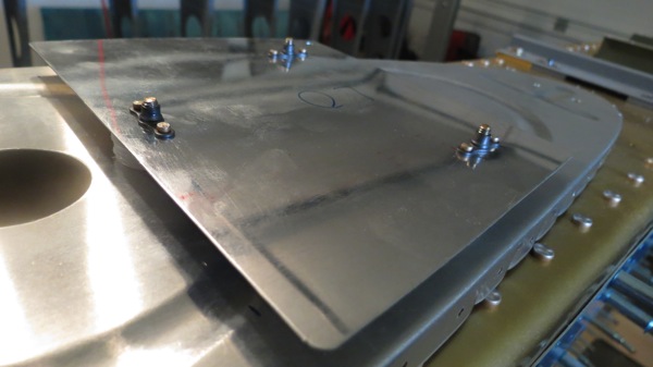
For once, this wasn’t just me putting things together just for fun. The assemblies need to be test-fitted in the tank to ensure proper clearance with the stiffeners; the instructions call for at least 3/16” between the two. So I got to work clecoing the two ribs into the skin. The inboard assembly was fine – the outboard one, not so much:
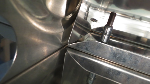
The instructions allow for trimming either the stiffener or the plate. I figured the plate was a better bet since it has about 20 times more material than the stiffener. So I marked where the stiffeners contacted the plate, removed the assembly, marked out cut lines, roughed it out with the bandsaw, cleaned up the cuts, and did the whole test fitting thing again.
Much better:
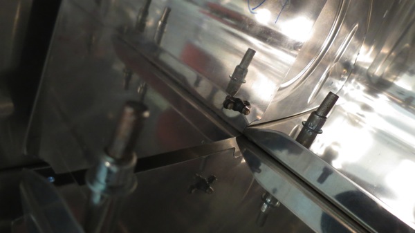
That’s about all that can be done with the sender plates for now. Actually, all that remains is installing the BNC connector on the inboard rib and running the wire connecting the plates; I’ll leave that until the tanks are closer to final assembly, since doing that bit of work required tank sealant.
So I turned my attention to the inboard ribs. These need to be cut for the tank access plates, which means cutting a nice 5.25” diameter circle. The “standard” tool for doing this is a fly cutter, a nasty little thing that lots of people seem to consider dangerous. I’d looked at getting one before and determined that it could probably be had at the Ace Hardware by the house, so I took a field trip over there. Alas, they did not have such a thing. I started to order one from Amazon, but then got to researching and found where a VAF member had tried a different tool, a hole-cutting mill thingy used by HVAC people to cut holes. Oh, and it was available at Home Depot. It was more expensive than the fly cutter, but I could get it today, and it did seem a lot safer to use. So I made another field trip to Home Depot and came home with this:
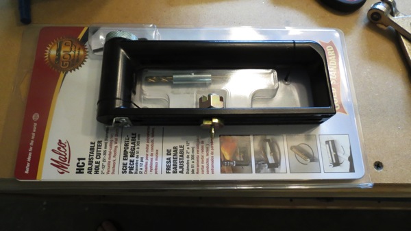
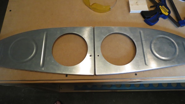
Basically, there’s a milling bit that goes in the left part and is attached to a drill. The center pivot is set to the desired hole size, a center hole is drilled, and then you just pivot the whole assembly in that center hole while milling a nice circle. The thing worked quite nicely, and soon I had two nice access holes:
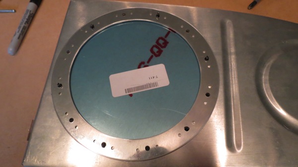
Next we need the access plate screw holes around the perimeter. The plate has prepunched screw holes, so it can be used as a handy drill guide. After drilling the screw holes in both ribs, I clecoed the plate and interior doubler in place just so show the setup.
Exterior side:
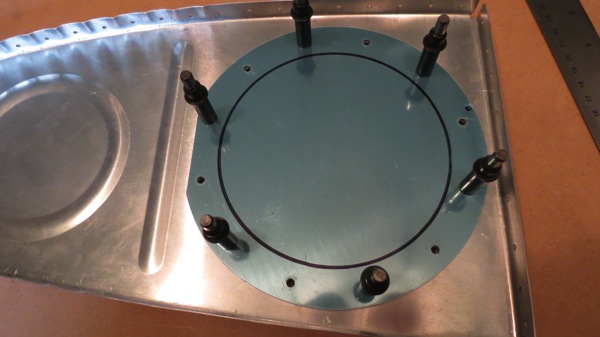
Interior side:
Normally these plates would mount both the fuel pickup and the float-type fuel sender, but I’m not using the floats in favor of the capacitive senders, and only one of my tanks will get the normal fuel pickup. I decided to mount a flop tube in the right tank to allow for sustained inverted flight. I don’t exactly have any plans to do a bunch of upside-down flying – which would also require an inverted oil system – but I figure I might as well build this in while I’m doing the tanks rather than finding occasion to retro fit the flop tube down the road. About the only downside to doing this is that the flop tubes do wear out after a while – they get stiff and can potentially not have enough flop left to get to the fuel in the bottom of a tank. So this will be something I’ll have to keep an eye on and potentially replace. General consensus seems to be that the life of a flop tube is five years or so. (I considered putting flop tubes in both tanks, but then I’d lose some redundancy if both tubes got stiff at about the same rate. With a standard pickup in one tank, I can count on the left tank always being able to get maximum usable fuel out of the tank.)
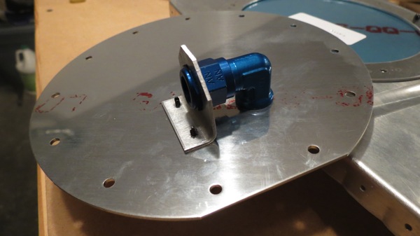
Anyway, the main point of that is that the flop tube, unlike the normal pickup, has its fitting towards the forward end of the rib. So the access plate for the right tank needs no modification. The left plate, however, gets drilled for the AN fuel fitting as well as the anti-rotation bracket. That bracket, true to its name, prevents the fitting from rotating, which could potentially pull the pickup out of the usable fuel, which would be…undesirable.
After drilling those two holes, I temporarily installed the fitting and bracket to get a look at the layout:
The bracket needs to be deburred before it’s riveted on, and it’ll also need sealant between it and the plate (as will the fitting), so no for-real installation just yet. Actually, I need to take care of the pickup itself first. The plans have you make your own pickup out of tubing, but most folks seem to buy prefab pickups from Van’s instead. I’m kind of torn between ordering the prefab – which would prevent me from working on this plate any more until late next week – or just going ahead and making my own. Decisions, decisions.
In any case, there was stuff to be done around the house, so I called it a day. Got some stuff going on tomorrow, but I may have a couple hours to get out in the garage anyway. If so, I’ll probably get the cap and drain flanges fitted and drilled. That should be relatively straightforward, good for a short day. I can also drill the inboard ribs for the fuel sender connector and the tank vent line fitting – at which point I think I’ll have most of the pre-assembly stuff done, save for deburring and dimpling the tank skins and ribs. These tanks are coming together pretty quickly! (so far…