Match drilled left leading edge, clecoed right wing skins

So my main objective for tonight was to get the skins clecoed onto the right wing skeleton. But first I had to address some other concerns; namely the very real possibility of not having enough silver clecos. I’d done a sort of quick and rough estimate Sunday night, and it was looking like my supply would be marginal to get the right skins on. So my plan was to remove some of the clecos I had holding the leading edge together.
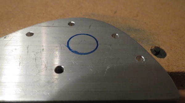
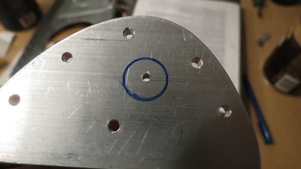
I couldn’t recall if I’d match drilled the left leading edge yet, but I was pretty sure I hadn’t, and I turned out to be correct. So I decided to go ahead and match drill it while it was thoroughly clecoed, then remove about half or so of the clecos. With match drilling complete, the only real purpose of the clecos would be to keep the assembly together in a minimal fashion.
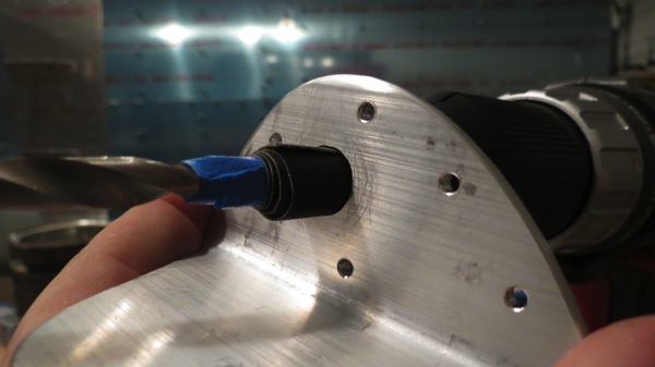
But first I wanted to take a look at the leading edge rib flanges that attached to the spar. Last time I put the leading edge in place, it seemed like I had to pull a bit to get everything lined up, so I suspected that some of those flanges weren’t quite square. A quick check confirmed my suspicion, and a bit of work with the hand seamers fixed that problem. This time, the leading edge went on the spar and it lined up without any trouble. Match drilling went pretty quickly from there; the skin-to-rib holes were stupid easy, though the rib-to-spar holes required me to use a long drill bit instead of my usual reamer due to tight clearances.
Hey look, the left wing is back together again:
IMG 2124
So I slid on over to the right wing and got to work clecoing. I’m pretty sure I said this when I did the left wing, but there are a lot of clecos here. I would estimate I spent a solid hour just on this task. I did the top skins first, then moved on to the bottom, working from inboard to outboard. I was down to the last few clecos when I noticed something wasn’t right. Oh, I see, the skin is interfering with the lower outboard arm of the wing stand.
Hrm, that’s a problem:
IMG 2125
So I proceeded to remove all the clecos outboard of the third rib, which allowed me to pull the skin out of the way. I also had to detach the outboard spar ends from the arms so I could pivot the wing out of the way. Only then was I able to get in with a hacksaw and start cutting a notch in the arm. Some cleanup with the Dremel, and all was well again:
IMG 2126
Of course, since I’d moved the wing around, I felt compelled to break out the plumb bobs again just to make sure I hadn’t introduced any twist into the wing while moving it. Everything checked out though, and now the wing is all set for match drilling…another night.
IMG 2127

Posted in Wings | Hours Logged: 2.5

Right wing on the stand

Finished setting up the right wing on the stand tonight. As with the left wing, there were some modifications that had to be made to the stands, but I’m pretty sure things went faster this time since I’ve done all this before. Now the skeleton is fully clamped in place, all sag and twist removed, and ready to accept the skins for match drilling.

After getting the stand all set up, I decided to go ahead and prime the tank attach countersinks, so I set about masking everything and shot the primer. Funny how the masking takes about six times longer than the actual priming…

No photos tonight, nothing really worth seeing.

Posted in Wings | Hours Logged: 2

Right skeleton riveting complete

Well, not much of a work day, but I got my milestone done anyways.  We ran down to the coast with the dogs in the morning, and while we were down there, my allergies starting getting bad, to the point that when we got home around midafternoon, I immediately drugged myself and took a nap. I woke up feeling a bit better, so I headed out to squeeze some rear spar rivets.

Not really much interesting happened with this, though I had a couple of ribs whose flanges wanted to pop away from the spar web when I squeezed the rivets. I ended up drilling out a few rivets and working up a system with a wood block and a clamp to hold the flanges flush while staying out of the way of the squeezer. Once I got that technique down, I had pieces sitting nice and flush. I also inexplicably found a couple of empty rivet holes between the rear spar web and the reinforcement fork, which I riveted together over a year ago. I guess I somehow thought those were holes I needed to leave open for some reason. Who knows…I just squeezed the rivets in there and moved on.

There were a couple spots on the rear spar where the primer had gotten messed up, so I decided to shoot some touch-up primer. While I was at it, I took care of another task that I should have done a long time ago. The main spar is gold anodized, but the spots where it’s countersunk for the tank attach screws are supposed to be spot primed. Since I was priming anyway – the main consequence being that I turned the A/C off and opened the door (in the process realizing that Houston in August is still stupid hot even at 10 PM) – I decided to mask the left skeleton and shoot primer there too.

Lots of masking tape and newspaper:

IMG 2116

IMG 2119

And the finished product:

IMG 2120

Looks a little bit ghetto, but I’m not really bothered. This area is going to be covered anyway.

After letting the primer fumes die down for a bit, I recruited Josie to help me move the right skeleton onto its stand. Now I have *two* wing skeletons!


IMG 2121

The sag in the right wing (right side of the photo) is pretty noticeable. All I did was bolt/clamp the main spar to the stands tonight; I still need to go through the whole ritual of removing the sag, checking for twist, and finally clamping the rear spar to the stands as well. I’ll do that tomorrow night and maybe go ahead and mask the right spar and prime those countersink holes too. Might as well go ahead and get them done now.

It shouldn’t take me too long to get the right wing to the same point of assembly as the left one – I think the main tasks are going to be match-drilling the skins and fitting the leading edge and tank. Or to put it another way, I don’t think I’m going to be able to put off sealing the tanks for much longer…

Posted in Wings | Hours Logged: 2.5

Right skeleton riveting

This post sort of covers two days. I did get out in the garage last night, but only for about an hour. All I did was prep the replacement rib I got in from Van’s; reamed the spar attach holes to #30, cleaned up the edges, checked the flanges for squareness, fluted the thing, and undertook my favorite task of removing burr in the tight spots with needle files. I also drilled the holes in the lightening hole for the wing conduit, and finished off the night by getting Josie to help me move the right spar back to the workbench.

Saturday, the first order of business was to get that rib primed. After it was done and drying, I recruited Josie to come out and help me shoot rivets in the main spar. She also had a good (but late) idea; she asked why some of the ribs were already riveted, and I explained that with the flanges facing one way, I could easily access both sides and shoot the rivets solo, but when the flanges faced the other way, it was too awkward. She gave me a funny look and asked why I didn’t just turn the spar over.

It’s amazing the things that you never think of until someone else points them out. *sigh*

Anyway, we got all those rivets shot, and then I moved on to the two remaining inboard ribs. Before riveting those, I made use of what I’d learned about the tank attach nutplates. On the left spar, I riveted those before riveting the wing walk ribs, since I’d have a lot more room. Then I learned that I needed the nutplates out of the way so I could drill the inboard tank attach angle. Well, in this case, it occurred to me that there was no reason I couldn’t go ahead and drill that attach angle, so I did just that.

Then I set about riveting those nutplates. I didn’t have much problem on the left spar with these, but here I did much worse. I had ridiculous trouble keeping the flush set in place, and messed up two rivets. And since I was using NAS rivets here, I didn’t think I could safely drill the heads off, so instead I ground off the shop heads with a Dremel, which also messed up the nutplates.

I then took a different approach to these things. I recruited Josie once again, this time to help me back rivet those nutplates. Obviously the back rivet plate won’t work here, but really all you need is a good flat object to hold on the manufactured head side. So I just gave Josie the tungsten bucking bar, and we shot all four rivets in about five minutes, and they were beautiful.

That just left the two inboard ribs to rivet, which I easily did solo, and then it was time to bring out the rear spar and cleco it in place. I briefly considered squeezing a few rivets back there, but it was after 11 and I figured I’d quit for the night. So instead I cleaned up a bit, and of course took the requisite photo of the skeleton:

IMG 2113

But it turned out I wasn’t done. I was about to head inside, feeling quite good about myself, when I looked at the inboard-most rib. Turns out I drilled the holes for the wing conduit mount on the top of the lightening hole instead of the bottom:

IMG 2115

At least I still had my drilling jig around, so it was a simple matter of clecoing it in place and zapping the two holes.

I also took an inventory of my K1000-3 nutplates, which are the ones used for the tank-spar attach angles. When I grabbed the three to rivet to the spar, it didn’t seem like there were many in the bag. I wasn’t sure how many extra were in the kit, but I’d ruined two tonight in addition to the three I removed from the left spar, so there was a good chance I might be short. And I was right – I only have thirteen left, but I need eighteen for the remaining attach angles. We’ll, it’s been a while since I sent Aircraft Spruce some money.

Since I was already ordering from them, I also ordered some MSP-42 and -44 blind rivets. I’m going to use these to rivet the leading edge assemblies to the main spars instead of solid rivets; things are really tight up there, and Van’s has approved the use of LP4 blind rivets here. I’m going a step further by using the stronger Cherry rivets, partially because I already have a big bag of MSP-43s. I also ordered a tube of fuel lube, which I’ll eventually need for some tank fittings and so forth.

Tomorrow I should be able to get the rear spar riveted, and then this skeleton can go live on the stand for good!

Posted in Wings | Hours Logged: 5

Left tank plumbing

Came home today to a nice little gift from Van’s: the prefab fuel pickup I ordered! Time to get some more work done. My goal for the night was to temporarily assemble the left tank with all the bits and pieces in place so I could verify that everything was in place for eventual assembly.

The main thing that needed addressing was the fuel vent line. First up, I needed to drill the inboard rib for the vent line bulkhead fitting. The plans aren’t picky about the location of this, so I located it as best I could off the plans and first drilled a small pilot hole. Then I clamped both inboard tank ribs together and drilled a larger pilot hole through both; this will give me consistent location of the fitting between wings. Not super important, but it assists with my neurosis of symmetry. Finally, I opened the holes to full size with a Unibit.

Here’s the left inboard rib with the vent fitting hole (top center) and the new fuel pickup in place as well:

IMG 2106

Next up was the vent line itself. One issue here was that I’d be needing to flare the inboard end of the tubing…did I mention I’ve never flare a line like this before? Fortunately there’s lots of extra tubing, especially since I’m going to use soft lines for the pitot tube instead of the aluminum stuff, so I cut myself a test length, did some reading up on technique, and went to town. It took a few tries before I got the hang of the tool and started making good in-spec flares.

Time for the real fun. I rolled out a length of tubing slightly longer than the width of the tank itself, giving myself some extra length in case I messed up the flare and had to do it over again. This turned out to be unnecessary, as I got the flare right on the first try (it’s a little more tense when you’re flaring a 4.5’ long piece instead of some random scrap). Next I clecoed the interior ribs to the top tank skin, inserted the snap bushings, and routed the vent line through the bushings. Then the inboard rib was clecoed in place, with the vent line bulkhead fitting preinstalled. From there, it was a simple matter to make the two gentle bends needed to get the vent line to mate with the fitting.

I was feeling quite proud of myself until I realized that I’d forgotten one thing: the BNC connector for the capacitive fuel sender. That required me to remove the inboard rib again so I could drill the required 3/8” hole with the Unibit. With the rib back in, I’m confident that this tank has all the little parts in place. All that’s left to do is final drill the screw holes in the trailing edges of the skin and get the skin and ribs deburred and dimpled, and this thing will be about ready to seal.

Here’s the inboard rib with all the fittings in place:

IMG 2107

Inside that same rib, showing the fuel pickup as well as the vent line routing to the bulkhead fitting:

IMG 2109

And the outboard end of the tank:

IMG 2110

Observant readers will note that the little clip I made last time is actually in the wrong place. Well…that’s what temporary assemblies are for, to figure out stuff like this. Imagine if I’d riveted that cap on before discovering this… Also, there’s obviously lots of extra material on the vent line. I thought about cutting it to length, but I want to put a little upward bend in the outboard end of the tube here to place it as high as possible. Doing so would make it difficult to get the line out, so for now I’m just leaving the extra material there. I’ll mark the cut point so I can trim it the next time this tank comes apart, and then I’ll do the final bend once everything is together for good.

On another note, I got in my replacement rib this earlier this week. I suppose I’ll get that prepped and primed this weekend, and maybe we can get the rest of the right wing skeleton riveted together in the near future. It’ll be nice to have that out of the way and more-or-less permanently affixed to the stands.

These wings are coming together fast enough now that I’ve found myself starting to consider when I should order the fuselage kit. Lead times are sitting at eight weeks, but the concern I have is storage space here. I’ll need to have the wings off the assembly stands before I have the floor space necessary to get the crate for the fuse kit in the garage. So it’ll be an interesting balancing act of ordering late enough to have somewhere to put the stuff, but early enough that I don’t end up with a bunch of downtime. Decisions, decisions…

Posted in Fuel Tanks, Wings | Hours Logged: 2

Left tank cap & drain

Lots of stuff to do this morning and tonight, but I did manage to get out in the garage for a bit. After thinking it over, I’m going to order the prefab fuel pickup from Van’s instead of making my own. About the only reason to make my own is so I can do it Right Now instead of waiting a few days. Well, that and paying shipping. It would have been nice if I’d discovered this last week before I ordered my replacement rib…oh well.

So instead I started out with the tank drain. This goes on the inboard rear corner, which is the lowest point due to the wing’s dihedral and the slope of the lower tank skin. There’s already a single prepunched hole for the drain, but the rivet holes aren’t there. So the drain had to be positioned, clamped, and then used as a drill guide for the skins.

Here’s the flange clamped to the inside of the skin:

IMG 2094

Getting that thing lined up and clamped was a bit painstaking. Right after taking this picture, I realized that the rivet holes alone the sides didn’t quite line up with the holes for the ribs. This bothered me a bit, and I almost unclamped and redid it. Then I thought if how annoying it would be to try and align the holes as well, and considered how many people were actually going to roll under the wing and criticize my alignment. Yeah, it’s fine as it is. I’m not building a showplane.

The flange actually mounts to the outside of the skin. At first I thought it was odd for this to be hanging out in the wind, but the reason is simple (and obvious in retrospect): The more the drain sticks up inside the tank, the less effective it is at removing contaminants and water at the bottom of the tank. There’s a guy who makes fairings for the drains; I’m thinking I might order and use them. If nothing else, it’ll help hide the not-quite-aligned rivets in the flange.

Here is it in place: (I should have clecoed this from the other side of the skin so you could actually see something other than clecos. Oh well.)

IMG 2096

Next up is the fuel cap. Things are kind of reversed here from the drain flange; the large hole and the rivet holes are in the skin, while the cap flange has no holes. So in this case, the cap is aligned and clamped in place and the skin used as a drill guide. What makes this fun is that the top of the flange is curved to accommodate the curve of the tank skin, so it has to be carefully aligned before drilling:

IMG 2097

If I thought lining up and clamping the drain was annoying, well…that had nothing on this. I think I needed about five hands to get this done efficiently, but I eventually managed to get it clamped in place:

IMG 2099

From there, I just started drilling and clecoing. Once I had a couple of clecos in place, I could remove those bulky clamps, and everything went pretty quick. Here’s the cap clecoed in place:

IMG 2100

Next the cap flange gets countersunk for the flush rivet skin dimples:

IMG 2101

Then there’s one final bit to be done. The fuel vent line will run from the inboard rib all the way out here by the cap, where it will terminate just outboard of the cap. So there’s a little bracket that is riveted in assembly with the cap to hold the free end of the vent line. This clip has to be fabbed from a strip of .025 sheet. The fun part is making the little curl that the 1/4” vent line will fit into. I puzzled a bit over how best to do this, and eventually settled on a combination of a drill bit, pliers, and the vise.

For my first attempt, I stuck a 1/4’ drill bit in the vise with the base sticking out; this would be my bend guide. Then I just held the end of the strip with pliers as I gradually bent it around the bit. This made for a nice circular bend, but the aluminum has enough springback that the tubing fit a little too loosely for my preference. So I tried again with a slightly smaller bit; this time the bend was a bit too small, but I was able to force the 1/4” bit into it to size it back up a bit. After that, the tubing fit nice and snug:

IMG 2102


Then it was just a matter of bending the free end to position the tubing nice and high on the skin, then trimming it and drilling the rivet holes. Here’s the finished clip clecoed in assembly with the cap:

IMG 2104

At this point there’s not really anything left to do on this tank that doesn’t involved sealant. I suppose tomorrow night I can do all my hole deburring and dimpling on the skin and rivets. Before I can seal, I need to pick up some supplies, most notably MEK for cleaning mating surfaces. I suppose another Home Depot run is in order. I’m almost tempted now to keep going on this tank even after the replacement rib comes in…

Posted in Fuel Tanks, Wings | Hours Logged: 2

Left fuel tank stuff – senders, access plates, oh my!

When we left off last night, I’d just started to play with the capacitive fuel sender plates. This morning, I got right back on that. I started by repeating last night’s work for the inboard plate – locating and drilling the mount holes in the tank rib. Next, I needed to install the nutplates for the rib-to-plate attachments. These use flush-head rivets, which are kind of unnecessary since the plate doesn’t butt up against anything, but whetever. If I’d had some round-head -3 rivets I probably would have used this, but I didn’t. I did decide to try something new – instead of using the standard 426 rivets for the nutplates, I used NAS1097 rivets. These are commonly referred to as “oops” rivets, because their flush head is smaller than normal, corresponding to the next smaller size rivet. So for example, if you’re driving skin rivets, mess one up, drill it out, and mess up the hole, you can simply drill the hole out to #30 and install a NAS1097 rivet – the head will fit the existing dimple, while the shaft is larger to fit the hole.

Anyway, NAS1097-3 rivets also work well for nutplates – instead of having to either countersink for the larger head, or else dimple and then worry about maybe dimpling the nutplate, you just make a very shallow countersink and there’s much less drama. The countersink is in fact small enough that it’s easily done by hand. The smaller head isn’t an issue because these rivets see basically no stress – their function is simply to hold the nutplate in place and keep it from twisting while the screw/bolt is installed.

After riveting the nutplates on both plates, I installed them on the ribs using the provided spacers. Here’s the outboard assembly:

IMG 2084

For once, this wasn’t just me putting things together just for fun. The assemblies need to be test-fitted in the tank to ensure proper clearance with the stiffeners; the instructions call for at least 3/16” between the two. So I got to work clecoing the two ribs into the skin. The inboard assembly was fine – the outboard one, not so much:

IMG 2085

The instructions allow for trimming either the stiffener or the plate. I figured the plate was a better bet since it has about 20 times more material than the stiffener. So I marked where the stiffeners contacted the plate, removed the assembly, marked out cut lines, roughed it out with the bandsaw, cleaned up the cuts, and did the whole test fitting thing again.

Much better:

IMG 2088

That’s about all that can be done with the sender plates for now. Actually, all that remains is installing the BNC connector on the inboard rib and running the wire connecting the plates; I’ll leave that until the tanks are closer to final assembly, since doing that bit of work required tank sealant.

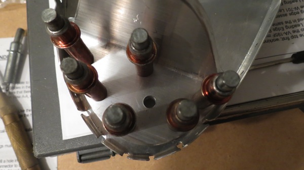
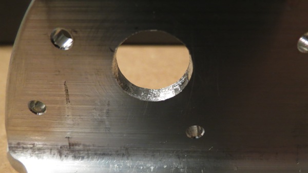
So I turned my attention to the inboard ribs. These need to be cut for the tank access plates, which means cutting a nice 5.25” diameter circle. The “standard” tool for doing this is a fly cutter, a nasty little thing that lots of people seem to consider dangerous. I’d looked at getting one before and determined that it could probably be had at the Ace Hardware by the house, so I took a field trip over there. Alas, they did not have such a thing. I started to order one from Amazon, but then got to researching and found where a VAF member had tried a different tool, a hole-cutting mill thingy used by HVAC people to cut holes. Oh, and it was available at Home Depot. It was more expensive than the fly cutter, but I could get it today, and it did seem a lot safer to use. So I made another field trip to Home Depot and came home with this:

IMG 2089

Basically, there’s a milling bit that goes in the left part and is attached to a drill. The center pivot is set to the desired hole size, a center hole is drilled, and then you just pivot the whole assembly in that center hole while milling a nice circle. The thing worked quite nicely, and soon I had two nice access holes:

IMG 2090

Next we need the access plate screw holes around the perimeter. The plate has prepunched screw holes, so it can be used as a handy drill guide. After drilling the screw holes in both ribs, I clecoed the plate and interior doubler in place just so show the setup.

Exterior side:

IMG 2091

Interior side:

IMG 2092

Normally these plates would mount both the fuel pickup and the float-type fuel sender, but I’m not using the floats in favor of the capacitive senders, and only one of my tanks will get the normal fuel pickup. I decided to mount a flop tube in the right tank to allow for sustained inverted flight. I don’t exactly have any plans to do a bunch of upside-down flying – which would also require an inverted oil system – but I figure I might as well build this in while I’m doing the tanks rather than finding occasion to retro fit the flop tube down the road. About the only downside to doing this is that the flop tubes do wear out after a while – they get stiff and can potentially not have enough flop left to get to the fuel in the bottom of a tank. So this will be something I’ll have to keep an eye on and potentially replace. General consensus seems to be that the life of a flop tube is five years or so. (I considered putting flop tubes in both tanks, but then I’d lose some redundancy if both tubes got stiff at about the same rate. With a standard pickup in one tank, I can count on the left tank always being able to get maximum usable fuel out of the tank.)

Anyway, the main point of that is that the flop tube, unlike the normal pickup, has its fitting towards the forward end of the rib. So the access plate for the right tank needs no modification. The left plate, however, gets drilled for the AN fuel fitting as well as the anti-rotation bracket. That bracket, true to its name, prevents the fitting from rotating, which could potentially pull the pickup out of the usable fuel, which would be…undesirable.

After drilling those two holes, I temporarily installed the fitting and bracket to get a look at the layout:

IMG 2093

The bracket needs to be deburred before it’s riveted on, and it’ll also need sealant between it and the plate (as will the fitting), so no for-real installation just yet. Actually, I need to take care of the pickup itself first. The plans have you make your own pickup out of tubing, but most folks seem to buy prefab pickups from Van’s instead. I’m kind of torn between ordering the prefab – which would prevent me from working on this plate any more until late next week –  or just going ahead and making my own. Decisions, decisions.

In any case, there was stuff to be done around the house, so I called it a day. Got some stuff going on tomorrow, but I may have a couple hours to get out in the garage anyway. If so, I’ll probably get the cap and drain flanges fitted and drilled. That should be relatively straightforward, good for a short day. I can also drill the inboard ribs for the fuel sender connector and the tank vent line fitting – at which point I think I’ll have most of the pre-assembly stuff done, save for deburring and dimpling the tank skins and ribs. These tanks are coming together pretty quickly! (so far…

Posted in Fuel Tanks, Wings | Hours Logged: 6

Left attach angles, fuel sender plates

Work continues on the left tank while I wait for my replacement rib. With pretty much everything match drilled, I moved on to working on the end rib reinforcements. The outboard end of the tank just gets a plate riveted on its inside face, while the inboard rib get that plate along with one of the attach angles I fabled up last weekend. This angle will eventually attach to the fuselage to help carry the weight of the tank.

To start with, I laid out the rivet hole locations based on the plans:

IMG 2079

Then I center punched those locations and went over to the drill press to drill the holes:

IMG 2081

Now the angle can be used as a drill guide for the rest of the assembly. The fun here is that according to the instructions you should clamp everything in place and drill it in assembly. Easier said than done, since both the angle and the plate need to be carefully located, but on opposite sides of the rib. After (unsuccessfully) trying a couple ways to do this, I came up with a better idea. First I just clamped the angle in place, then drilled two of the rivet holes. Next I removed the angle, flipped the rib over, and clamped the reinforcement plate in place. Then I used the two holes I’d just drilled i the rib as a guide to drill two holes in the reinforcement plate. Now I was able to cleco the whole assembly together and drill the remaining four holes in assembly.

The finished assembly clecoed together:

IMG 2082

I also used the newly-drilled inboard reinforcement plate as a guide to drill the outboard plate, then I clamped that plate in place on the outboard rib and drilled it too.

I wasn’t quite ready to call it a night though. So what next? I decided to look at the capacitive fuel sender plates. I reread the instructions, got out the pertinent ribs for the left tank, and started by drilling the mount holes in the rib for the outboard sender plate. The assembly is drilled to #21 and then the rib holes are enlarged to 1/4”. The reason for the larger holes in the ribs is that the screws that will attach the sender plate will be surrounded by nylon tubing, presumably to ensure the plate is electrically isolated from the rib.

Interestingly, while there are two sender plates per tank, there’s only one wire that connects both plates to a single-terminal connector that will be mounted on the inboard rib. Somehow I was expecting there two be two wires, one to each plate, with the sender measuring capacitance between the plates. I can only assume that in fact the capacitance is measured between the two plates and the tank structure itself. Maybe the outer screw portion of the connector is the “other” terminal? I’m going to ask on VAF about this. Not that I’m worried about doing things wrong – the instructions are pretty clear – but mainly because I’m just curious, and I like to know how things work.

Anyway, here’s that outboard rib with the plate resting on top of the spacers that hold it away from the rib. Basically just a quick look at how the plate arrangement will look:

IMG 2083

Tomorrow I suppose I’ll keep moving on the sender plates, and maybe after that, I can do the flanges for the fuel cap and tank drain.

Posted in Fuel Tanks, Wings | Hours Logged: 2

Match-drilled left tank

I went out to the garage with pretty low expectations tonight. I figured I’d aim to shoot all the main wing rib rivets that I could manage by myself, and then just kind of wing it from there. Well, there were exactly three ribs I could do solo, so that took all of about…maybe 30 minutes. Josie is busy working overtime for a big work project, so I couldn’t recruit her to come out and help rivet.

One of my main short-term goals is to get this right wing skeleton finished so I can clear it off the workbench; right now workspace is hard to come by. Between Josie’s unavailability and needing to wait for that replacement rib (which should be here Monday), it seemed that being productive this weekend was going to be tough. So I decided to abandon riveting on the right wing skeleton for the time being, and we moved it over to the wing stand. That freed me up to do some more work on the left tank.

First order of business was to drill the attach screw holes on the outboard edge of the tank. These screws will go into nutplates that will be on the W-423 joint plate. This was pretty straightforward, but before drilling, I double-checked everything to ensure that the tank was in the proper place. It’s been a couple weeks since I last set it up there, and it’d be really annoying to misdrill holes because I didn’t verify alignment and such.

Here’s a picture of a #19 hole for one of the screws. Exciting, huh?

IMG 2074

From here, I’d figured I’d pull the tank off and start looking at all the various internal parts. But then it occurred to me – I already had the thing clecoed together, and it was going to need to be match-drilled at some point…might as well take care of that now. First I pulled the tank off the spar, set it in the cradle, and match-drilled the baffle-to-rib holes. For the skin-to-rib holes, I put it back in place on the spar; the cradle limits access to some of those holes.

With that done, I marked the ribs and pulled the whole tank apart again:

IMG 2076

I was on a roll, so I figured I’d go ahead and get all the match-drilling done. The only things left were the stiffeners for the bottom of the tank, which I cut and prepped a few days ago. So i got those out, clecoed them in place, and match-drilled them too.

IMG 2078

The only prepunched holes that still need attention now are the attach screw holes along the aft edge of the skin. These just need to be drilled out to final size. However, I seem to recall reading something about problems with these holes cracking when dimpled. I think there was a specific approach to prevent those cracks, so I’m going to research that before I do anything.

I suppose tomorrow I’ll really get into the nuts and bolts of the tank’s innards.

Posted in Fuel Tanks, Wings | Hours Logged: 3

Removed a rib

So I ended up shooting an email to the support folks at Van’s for their input on my bad rivet from Monday. A few guys on VAF had indicated that the rivet might be OK to leave as-is. I liked the idea of not drilling it out, but I was skeptical of it being good. So I figured I’d ask the official authority. Sadly, the response was not what I’d hoped for – I was advised to remove/replace the rivet. Not a particularly surprising response though.

On the way home from work today, I stopped by Home Depot and bought myself a work light. The general garage lighting is OK, but not great, but I don’t have the freedom to install a bunch of fluorescent strips like I did in Atlanta. I’d figured I’d end up getting a tripod light for lighting specific tasks at some point, and today was the day. Nothing fancy, but I did spring for the LED light over a halogen model. I’ve worked with the halogens before and they get HOT. I’m in Houston, I don’t need any more heat in the garage.

Look, a light!

IMG 2070

It brightens up the work area quite nicely:

IMG 2071

But enough fun and games, time to get down to business. Best-case scenario, I’d remove the one bad rivet without damaging anything, replace it, and be on my way. The challenge was getting the head off with it so far off-center. I drilled into the head as normal, attempting to be conservative, and got the head off, but it was to no avail – I’d put a little divot in the rib flange right beside the rivet hole.

The good news was that I went into this figuring there was a good chance I’d end up trashing the rib, so I was mentally prepared for something like this. And in a way, it was liberating – once I knew the rib was going away, I no longer needed to be careful with it. That freed me up to not have to be perfect while removing the other four rivets, and once they were off, I could just wrench the rib out of place with no regard for its survival.

That, however, was the easy part. Solid rivets swell when they’re driven, so a lot of their grip strength comes not from the heads, but from friction between the rivet shaft and its hole. That means that the thicker the material, the more grip there is from the shaft – which means that they’re a lot harder to drive out for replacement. I always get worried doing this, because I have to hit the punch pretty hard, which makes me worry about the punch slipping and damaging something. That worry goes up a notch when that something is the main wing spar.

Fortunately, I’ve developed a method for getting these rivets out that works pretty well. Once I have the head off, I start by drilling a very small pilot hole into the rivet shaft. Once that hole’s done and I’m convinced it’s well-centered, I open the hole up with a #40 drill. This is smaller than the #30 hole the rivet sits in, so I have some wiggle room. The point if doing this is twofold: it removes material to give the rivet room to deform and let go of the hole, and it also makes a nice “socket” into which I can insert the punch to drive the rivet out. No more worries about the punch slipping!

Even with all that, these things are tough to get out. I’ve taken to using the rivet gun with a flush set to drive the punch instead of tapping it with a hammer, and every one of these five rivets required that technique. None of them would budge with hammer hits.

But I got them out, and all the holes in the spar are in good shape. It cost me a rib, but that’s a small price to pay. It’s a $20 part after all.

I wanted to take another picture, but I didn’t know what to take a picture of. So here’s a picture of the rivets after I drove them out of their holes:

IMG 2072

Posted in Wings | Hours Logged: 1