So remember how I had that idea that I could finish all the tank internals this weekend? Let’s all laugh out loud in unison…OK, it’s not that bad, but I did fail to consider how things were complicated by the flop tube in this tank. That means that I’m not just repeating work I already did once, and even better, there are some not-very-well-documented steps to be done.
I started the day by working on the fuel sender plates. This of course was something I’d done before, so it went pretty quick. Rather than go through the whole trial-and-error fitting of the outboard plate to ensure it had sufficient clearance from the stiffeners, I used the trimmed plate from the left tank as a template to go ahead and trim the right outboard plate. That wasn’t quite enough though, as on the first test-fit, the aft corner didn’t have sufficient clearance from the stiffener. No worry though…pull it off, remove some more material with the Dremel and cutting bit, deburr, test again…much better.
With the plate done and set aside, I moved on to working on the inboard rib in general. First I clecoed the access plate reinforcement ring in place and drilled/deburred all the nutplate rivet holes. Then it was time to deal with the reinforcement and attach angle on the nose of the rib.
This is where things start to get interesting; while the standard fuel pickup in the left tank went through the access plate, the flop tube goes in through that whole stack of material at the nose of the rib. So three pieces have to be drilled to 9/16” in assembly. But I don’t have a 9/16” bit, which meant I’d be using the unibit, which doesn’t have deep enough steps to cut the whole assembly. Thus, I had to drill each piece separately.
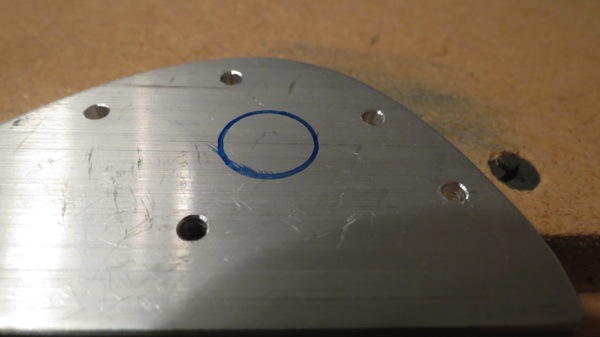
First, I laid out my hole location on the attach angle, trying to roughly center it between three of the rivet holes:
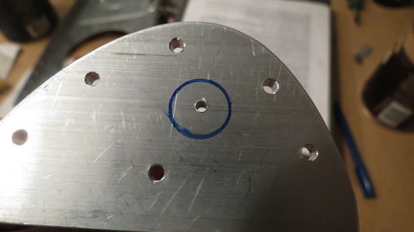
Then I center punched and drilled a small #40 pilot hole:
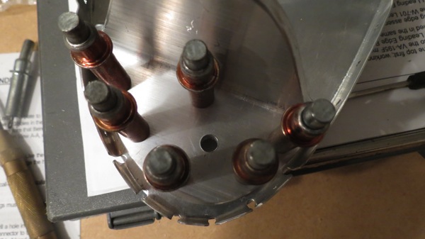
Now the whole assembly gets clecoed together and the pilot hole is enlarged to 1/4”, through all the pieces:
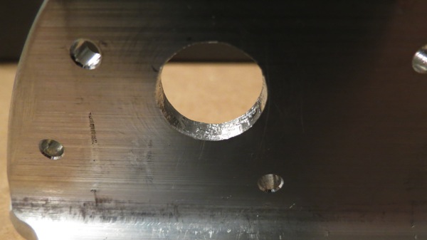
This is where things get fun. Making the hole in the rib and reinforcement plate was easy, but the attach angle is too thick to cut in one go with the unibit, so I had to enlarge the hole from one side, then flip the pieces and do the same from the other side as well. Between that and the bit chattering a little, the surface inside that hole was kind of ugly:
But how to smooth it? It was just slightly too small for one of the Dremel sanding drums to go in there. Finally, I came up with a field-expedient solution, a sort of ghetto flap wheel. I cut a strip of emery cloth, taped it to a 7/16” drill bit, and it fit nicely into the hole:
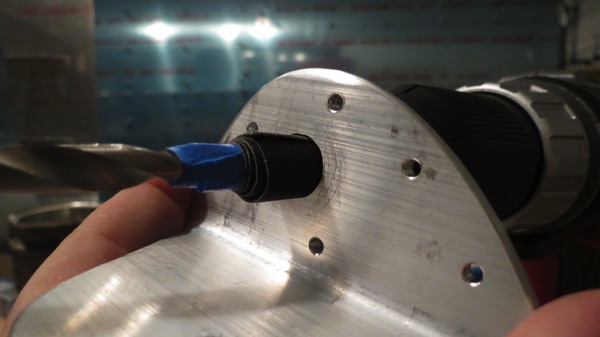
A little time with that cleaned up the hole nicely. Finally, I got everything clecoed together again and put the fitting and flop tube in place:
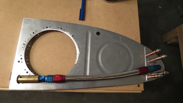
This led to some other questions in my mind, though. The norma fuel pickup has an anti-rotation bracket, which serves a dual purpose of preventing the pickup from threading off the bulkhead fitting and also preventing the bulkhead fitting itself from rotating and moving the fuel pickup off the bottom. The plans call for safety-wiring the flop tube to the bulkhead fitting, but there’s nothing to prevent the fitting itself from rotating in its hole. Granted, it’ll be torqued in place and hooped up with sealant, so maybe I’m overthinking it, but I figure I’ll run it by the VAF gang just to be sure.
With that done, I moved on to one of the tank modifications to go with the flop tube. The plans call for a little trapdoor to cover a hole in the first internal inboard rib; these holes allow fuel to flow between bays in the tanks, which works fine for level flight, but fancy stuff might cause fuel to move outboard, unporting the flop tube. So the trapdoor acts as a check valve to prevent this from happening.
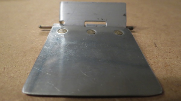
This is a part made from scratch, but it’s pretty simple: a square of 0.020” sheet, plus a little section of piano hinge. The end of the hinge is cut at an angle to provide a stop for the trapdoor itself. This was pretty straightforward stuff, though it did require me to make some executive decisions. For example, the plans show where to put rivets between the door and the hinge half, but don’t specify what type of rivets. But since the idea is for the trapdoor to sit flush agains the rib, it seemed that flush rivets were the order of the day. So I drilled #40 rivet holes, dimpled the door, countersunk the hinge, and put it together with 426-3 rivets.
Here’s the completed trapdoor assembly, from the backside:
And sitting roughly in place on the rib:
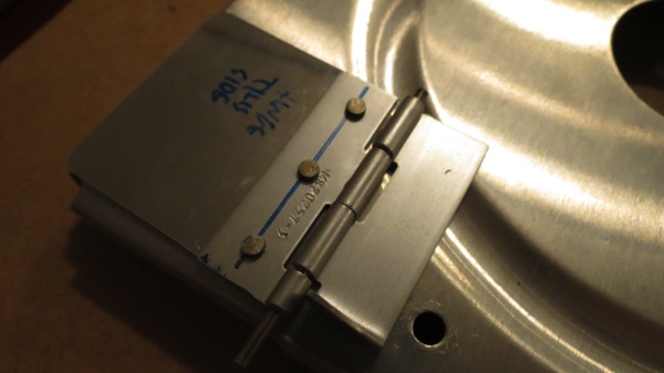
I didn’t drill/rivet the thing to the rib yet because, as the photo shows, the top hinge half goes across that stiffening channel, but there’s not enough material to put a rivet in the top right corner. I can put two rivets in the other part of the hinge half, but the plans call for three.So I’m not really sure what to do here…yet another question for the VAF brain trust, I guess. I suppose I could possibly cut another strip of 0.020 sheet and make a sort of bridge piece.
We’ll see…tomorrow…