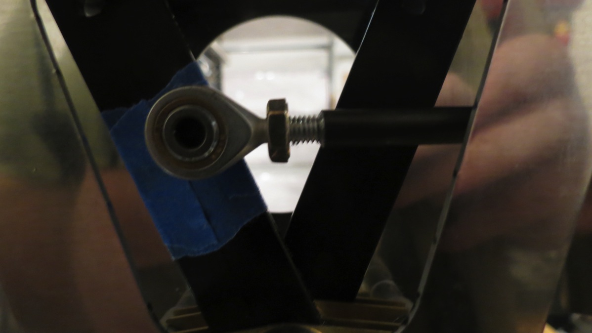
Finished aft bottom trim, began disassembly

So I didn’t get a whole lot done today in terms of shop time, but I’m well on the way to getting started on the monumental task of preparing all these parts. First off, though, I took a second look at the aft bottom skin. I made a few guide marks, removed the skin again, and took the Dremel to it. This time, it fit in place with good clearance from the mount all around. Here’s the final state, from below:

IMG 6481

And with the tail spring in place for a sort-of big-picture view:

IMG 6483

Here’s another view of the mount and the cutout, taken later in the afternoon after I’d removed the aft bottom skin and the bulkheads as a unit. The edges of the cut are still pretty rough; once I finish pulling this apart, I’ll file them smooth and deburr and so forth:

IMG 6496

There’s a lot more clearance around the mount than I would have preferred here. The weld on the aft portion of the mount, where it attached to the bulkhead, was the big clearance issue, and rather than shape the opening to fit around those, I was trying to maintain the smooth curve of the cutout. So by the time I had clearance around the welds, there was a ton of clearance everywhere else. But again, no one is ever going to see this, and it doesn’t really look that bad, just not-as-good-as-it-could-have. Not bad enough to need a new part, that’s for sure.

Trimming that skin was the last task prior to beginning disassembly, but first I went back through the instructions to review and ensure I didn’t miss any match-drilling. I was particularly concerned with the turtleneck skin (top portion of the tail); this was never match-drilled to the bulkhead tops. I was pretty sure it wasn’t called for but I wanted to be really sure – and it wasn’t. It’s probably not too surprising, since that piece won’t go back on again until much later. So, assured that I was done with it, I removed the turtledeck:

IMG 6487

The tail cone contained an absolutely ridiculous amount of aluminum chips from all the longeron drilling:

IMG 6489

IMG 6492

The real fun here was getting the forward aft bottom skin (the big obnoxious one) off. Try as I might, I could not get that thing to slide out from where it was sandwiched at the forward end. I actually ended up removing the aft side skins first and setting them aside; this gave me better access to really yank on the bottom skin, and finally I got the thing loose. For the moment, it’s sitting on top of the newly truncated fuselage assembly:

IMG 6493

Next up, the mid side skins will come off, and then the mid fuselage/seat rib assembly will be detached from the forward fuse. Then comes lots and lots of prep work. Unfortunately, I’ve got a lot going on tomorrow and I don’t think I’ll have a chance to get out in the garage, so further work will have to wait until next week.

Posted in Fuselage | Hours Logged: 2.5

Aft bottom skin trim

So yeah, tonight I worked on trimming this skin for the tailwheel mount. First I came up with a slightly better way to draw out the initial cut line: I measured and made a few guide marks on each side, then used those to position a template and draw each side of the cut line individually. This ended up with a much more symmetrical pattern than I had last time:

IMG 6474

I made the initial rough cuts using the bandsaw, then went to work with a Dremel and cutting bit to get everything looking good:

IMG 6477

This is where the real fun began; at this point, it became a highly obnoxious trial-and-error procedure. I’d go sit on the floor under the tail, try to fit the skin in place, mark where it was interfering with the mount, go back to the bench and remove some more material with the Dremel, go sit on the floor again, so forth and so on. All the care I took to make a nice symmetrical pattern for the initial cut was pointless, because the symmetry goes away once the fitting and trimming show starts. That nice smooth sweeping curve from the plans is pretty much impossible, because the weld joint at the aft end of the mount interferes with the skin. I was trying to maintain a somewhat smooth curve as I removed material, but by the time I got the skin to a point where I could cleco it in place, there was a pretty big gap everywhere *but* where the weld was.

Here’s the skin clecoed in place:

IMG 6478

Clearance between the skin and mount is still pretty uneven; there’s plenty of clearance on the aft end, but further forward I can’t even slip a little piece of aluminum in the gap. So I need to trim this some more, but I’d had enough of dealing with this for one night. I think I’ll do better tomorrow, when I’ve made peace with the fact that this cut isn’t going to be beautiful, just adequate. You’d need a mirror to even see this with the plane on the ground anyway.

Posted in Fuselage | Hours Logged: 1.5

Seat back support, tail spring mount

OK, we left off last time when I’d clecoed the seat back support into place. The support attaches to the side mount plates with AN4 bolts, and to the cockpit rails with a combination of -4 rivets and flush screws. The prepunch situation here is kind of odd; the cockpit rail holes that will hold rivets are prepunched in the rails and the spacer between the rails and the support. These holes are simply match-drilled through the support. But the holes that will hold screws are prepunched in the support, but not the rails or spacer, so they have to be match-drilled from below. (aka inside the cockpit)

The instructions say to drill the screw holes from below first, then the rest of the holes from above. But an issue here is that the 3/8” clecos I used to initially hold the support in place weren’t strong enough to pull the support fully into position. This is easily fixed with some clamps, but it makes drilling from below even more difficult. So I decided to drill the holes from above first, with the support clamped firmly in place. Then, with clecos in all those holes, the clamps could be removed and the support would stay in place.

That part was pretty easy, but next came drilling the support from below. I experimented a bit with trying to do this while leaning over from outside the cockpit, but I wasn’t at all confident in my ability to drill square to the surface, so I resigned myself to working inside. I prepared for this by tossing some scrap 2×6 pieces in the cabin. These are thick enough to at least make the rear seat crotch strap mount not jab into me while I work:

IMG 6454

And of course, once I climbed in there and laid down, I immediately realized I needed something else. Fortunately, I was able to get Josie’s attention so I didn’t have to climb back out. And of course, she couldn’t resist getting some photos of me being uncomfortable:

IMG 6455

IMG 6457

With that annoying task taken care of, I finished the support by drilling the screw holes out to #19, then match-drilling all the remaining holes. Next the center section bulkhead caps are match-drilled, then removed. I’m not sure why they were called out to be removed at this time, but I guess I’ll find out later…

Next up were the rudder stops. When I was cutting the piece of stock containing these pieces before, the blade on my bandsaw snapped and put a nice nick in one of these. At that time, I just decided on a whim to skip these external rudder stops in favor of an aftermarket solution that went inside the vertical stab spar. However, I did some more research on this topic today and it seems that there’s significant debate about those internal rudder stops. While there don’t seem to be any cases of damage or accidents resulting from the internal stops, a fair number of people (including one of the Van’s engineers) have expressed concerns with the internal stop causing increased stress on the vertical stab spar and the rudder hinge points.

After thinking it over, I’ve decided to use the factory external rudder stops instead of the internal ones. It turns out that the nick the saw blade put in the stop isn’t a problem anyway, as that part of the stop will be trimmed off later on. So I went ahead and clecoed and match-drilled the rudder stops in place:

IMG 6458

Next up is fitting the tail spring mount. Previously I drilled the mount hoes in the aft most bulkhead, and now with the tailcone together, it’s time to fit the mount and drill the holes in the next most forward bulkhead. The first thing that has to happen is the removal of the aft bottom skin. Well, that’s kind of a problem, since that’s exactly what’s resting on the sawhorse holding the tail up! Hmm, what to do…I considered modifying the saw horse so I could support the tail under the longerons, but that would have left the saw horse in my way while I worked on the tail spring mount. Finally, I realized that the two interior garage door track mounts in the ceiling were almost directly overhead the fuselage, just aft of the cabin. I tried running a ratchet strap between those two mounts, slung under the fuselage, and found that it was in a good location – about 6” aft of the aft cockpit bulkhead, and under the area reinforced by the baggage ribs. I lifted the fuse gently at first, confirming there wasn’t any distortion or buckling happening underneath, and it worked out great. (except I forgot to take a photo and now I’m too lazy to go back out and take one, so you’ll have to use your imagination)

Next I marked the forward bulkhead with a reference line, which I’ll want to align the top of the forward end of the mount:

IMG 6460

With the mount in place, there’s a bit of a gap between the forward end and the bulkhead. This is somewhat expected, as the instructions call for making shims as necessary to fill any gap:

IMG 6463

Here I departed slightly; the instructions specify 3/4” square shims, one for each of the two bolt holes. I elected to make a single shim that stretched all the way across the top of the mount; for one thing, it seems this will prevent the annoyance of individual shims spinning in place, plus there’s a little more contact surface between the mount and the bulkhead. That may well not make any difference, but I like it anyway.

Now the forward portion of the mount gets moved carefully into position and clamped in place. In addition to using the reference line drawn previously, the instructions say to use the tooling hole in the forward bulkhead as a reference also, by sighting down the mount tube and centering it like so:

IMG 6464

Finally, there’s nothing to do but check everything one last time and drill the holes. Here’ the mount in its final position, held in place only by clecos:

IMG 6467

Now the aft bottom skin has to be trimmed to account for that mount passing through it. There’s a nice full-size template in the plans for this, which I traced onto a sheet of paper:

IMG 6469

Then taped in place on the skin:

IMG 6471

And then a cut line is traced onto the skin:

IMG 6472

I’m not really 100% satisfied with how that traced cut line ended up though; it looks asymmetrical to me. I know it’ll end up being tweaked to fit the mount, but I want it to start off being straight. In any case, it was getting late by this time and I didn’t want to get into making the cut anyway, so I quit for the night. I’ll do some more research and see if I can get good ideas on marking and cutting here from other builders.

Posted in Fuselage | Hours Logged: 5

Cockpit rails

Well, didn’t get a lot done today. I got a bit of a late start, and after a couple hours work I broke for dinner, and about the time the power went out for what ended up being four hours or so. That kind of put a damper on the possibility of working into the evening…

Anyway, drilling the rails was kind of interesting. The instructions call for positioning them so they’re flush with the mid side skins, but with the rails clecoed to the tops of the center section bulkheads, there was 1/8” or more between them and the mid side skins. I was able to push on the longerons and bit and move them in close, which leads me to believe that the reinforcing plates between the skins and bulkheads aren’t quite sitting fully flush with the bulkheads. So I ran a ratchet strap around the fuselage and was able to use that to pull the longerons into proper alignment. I also used the strap to pull in the longerons at the gear towers, and drilled the five holes at the top of each tower to the longerons.

Next I clecoed the seat back support mounting plates in place and match drilled them, followed by the spacers that go between the rails and the seat back support weldment. Finally, I brought over the seat back support itself and clecoed it into place. At this point, I decided that the fuselage structure was sound enough for me to climb into this thing for the first time. I laid a piece of scrap lumber over the seat ribs and added some old towels for padding, and in I went.

Funny part was, as soon as our dog saw me sitting in there, he climbed up the stool to investigate, apparently trying to get in with me. Sorry Dude, it’ll be a few years before you can ride in here:

IMG 6440

IMG 6449

Posted in Fuselage | Hours Logged: 2

Tail stuff

Tonight I started by match-drilling the holes between the lower center section flanges and the forward floor and bottom skins. For some reason I’d thought that the instructions specified these be drilled from the inside, but apparently I dreamed that. That’s fine with me, because there’s lots of stuff in the way inside and nothing on the outside. The only downside was that I had to lie on the ground under the fuselage.

Next, I clecoed the aft bulkhead tops into place, then pulled the aft top skin out of the guest bedroom and clecoed it into place:

IMG 6439

Then I fitted the aft deck and drilled it in assembly with the longerons. The horizontal stab assembly will sit on top of the aft deck when it’s installed. Here’s the deck clamped in place prior to drilling:

IMG 6436

Next up will be the forward canopy rails…tomorrow…

Posted in Fuselage | Hours Logged: 2

Fuselage relocation

OK, not really a work day per say; all we did was get the fuselage off the old “platform” and onto the new sawhorses. We moved the fuselage out of the garage and into the lawn first. I took advantage of the newfound room to sweep/vacuum the floor, and roll the compressor out into the driveway and drain the tank. Then we positioned the new saw horses and moved the fuselage right back into place. I planned the saw horses pretty well – the upper longerons are within a few degrees of being level!

Next I’ll get to do…more match drilling. Whee!

IMG 6430

IMG 6434

Posted in Fuselage | Hours Logged: .5

More fuselage drilling

Well, this was mostly a day spent stress testing my air drills and compressor. Prior to that, though, I made a Home Depot run for some lumber, with which I made a couple of sawhorses. Now that I’ve finished drilling the tailcone, we’ll need to move the fuselage to these so it sits low enough for me to easily lean inside and do some drilling from in there. The sawhorses are specially-made for this job; one of them is 3’ wide but only a foot tall, and will sit under the forward end of the fuse, while the other is 2’ tall but only a foot wide, and it will support the tail. These should result in the fuselage being roughly level while it’s on the horses. I’m going to add some angle-cut blocks on the tail horse to help hold the tail securely, so that will allow me to adjust the level attitude if I wish – though there’s no particular call to have it be level right now.
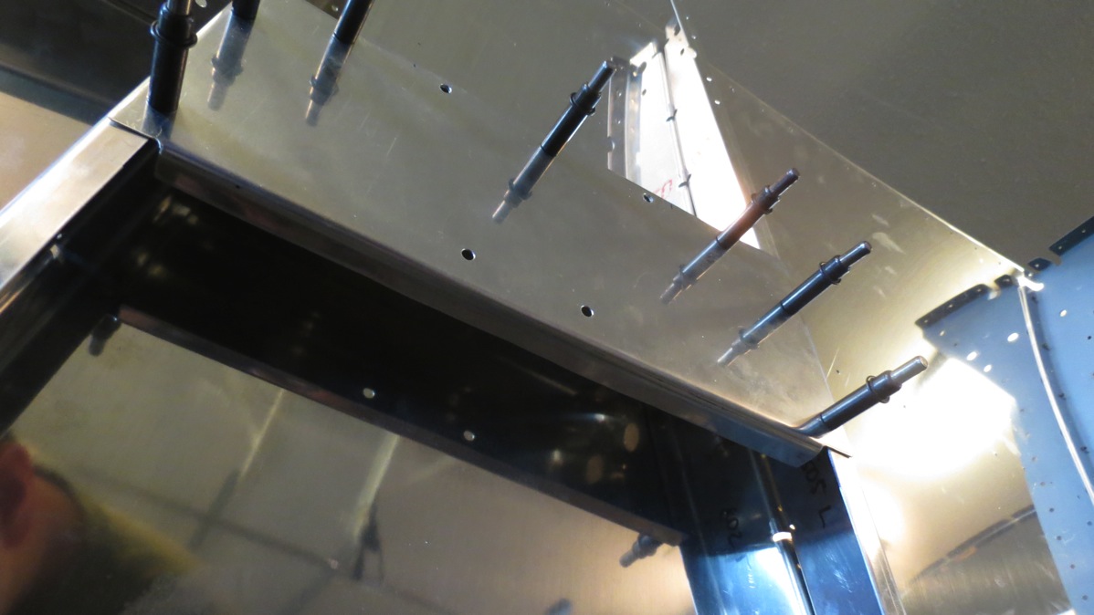
Anyway, these are the saw horses:

IMG 6419

And now back to the fuselage. With all the drilling done on the forward side skins, next the mid side skins get drilled. First the upper longerons are drilled in assembly, then all the other holes get match drilled. Next up are the aft bottom skins; these are lots of fun since I basically have to lie on the floor while drilling. And then the real fun begins, drilling the aft side skins to the longerons. This isn’t particularly challenging, there are just a l-o-t of holes. Once I got my drilling rhythm down, I think the compressor was usually running for 10+ minutes at a time. It actually got to a point where moisture was blowing through/out of the drill; I guess the air in the tank was so saturated that the water was condensing as the air expanded in the hose. I guess I’ll be wanting to go ahead and drain that tank again soon…

Here’s one of the longerons clamped to the aft side skin prior to drilling:

IMG 6423

And a forest of clecos on the other aft side skin:

IMG 6424

Speaking of clecos, these are all the silver ones I have left over after all this work, with the exception of a can of pretty junky ones on a shelf somewhere. Hopefully I don’t have to use those, I don’t want them fraternizing with my nice shiny clecos:
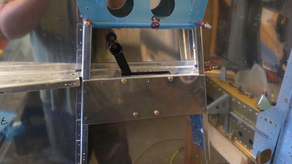
IMG 6429

I think tomorrow we’re going to go to an AOPA safety seminar in the evening, so I suppose Tuesday we’ll move the fuselage assembly out of the garage, get the floor swept (all that drilling made a ridiculous mess), and then get the fuselage set up on the saw horses. Pretty soon the aft top skin will go on, along with the cockpit roll bars, and at that point I think I’m going to have to throw a pillow or something in there and sit in this thing for the first time.
Posted in Fuselage | Hours Logged: 5.5

Rear seat finished, back to fuse drilling

Started out today by beginning to rivet the rear seat. This was somewhat interesting due to the shape of this thing. In general, it was challenging to find some way to hold the pieces steady while I riveted; in particular, the curved top section made it awkward to use the squeezer. So what I’m getting it is that it took a little longer than I expected. But still, it’s done, and so I of course put it in place in the fuselage for a photo op:

IMG 6416

Then I got back to work on drilling the fuselage. I got through drilling everything on the left forward side skin before quitting for dinner. Looking ahead, and based on the rate I was going at today, I think it’s possible I could finish match drilling everything back to the tailcone tomorrow. I’m going to run to Home Depot in the morning to pick up materials to make a couple sawhorses; the setup I have now is kind of wobbly and not exactly confidence-inspiring, plus I’ll soon need to climb into this thing to do some match drilling, so I’ll need it lower to the floor and definitely on something more sturdy than these cheap plastic sawhorses.

Posted in Fuselage | Hours Logged: 4.5

Rear seat back match drilling and stuff

Tonight I finished drilling one hinge half to the seat back and then clecoed the whole thing together for match drilling. Pulled it apart, deburred everything, and started to to some riveting, then decided to just wait until tomorrow. Once I get this seat back riveted, I’ll put it aside and get back to all the fuselage drilling.

Posted in Fuselage | Hours Logged: 1.5

Rear seat back prep

Short night. I started working on the rear seat back, even though I got in my package from Avery that included new shiny drill bits. I think I’ll wait until the weekend to go on another drilling spree.

Most of tonight was just deburring the edges and crevices of the seat back parts. The rear seat is more complex than the front one, so lots more little spots to clean up. Then I cut the hinge for the bottom of the seat. The plans call for removing four eyelets in the center of the hinge. I’m not quite sure yet what this is for; I guess something passes through here, but I dunno what.

IMG 6414

That’s about it. I should be able to finish this seat up Friday, and then this weekend it’ll be back to drilling the fuselage.

Posted in Fuselage | Hours Logged: 1.5