So before going to bed Thursday night, I worked up and put in an order with Aircraft Spruce for all the raw materials I was going to need for the throttle quadrant stuff. I was a little bummed that I figured out so late that I needed to order stuff, as I’d hoped to spend this weekend hashing out the linkage between the throttles. Well, I shouldn’t have been worried, as I spent the entirety of today just getting the rear throttle quadrant mounted.
Instead of ordering the throttle mount plate from Van’s – which, based on photos I found, I’d have to modify anyway – I decided to just make my own from scrap I had lying around. Really, it’s fairly simple for this piece – I figured out how tall it needed to be and cut the sheet with that dimension, then clamped the whole thing in place and marked the forward and aft edges to match the angle of the two bulkheads. The real fun is taking the resulting nice trapezoidal piece of sheet and match-drilling all the mount holes with the armrest and bulkheads, and then figuring out how to mock the throttle up in position to drill those four bolt holes. Once I got that done and I was sure of where everything would mount, I bent the excess material at the bottom of the plate inward to provide some rigidity to the lower edge of the plate.
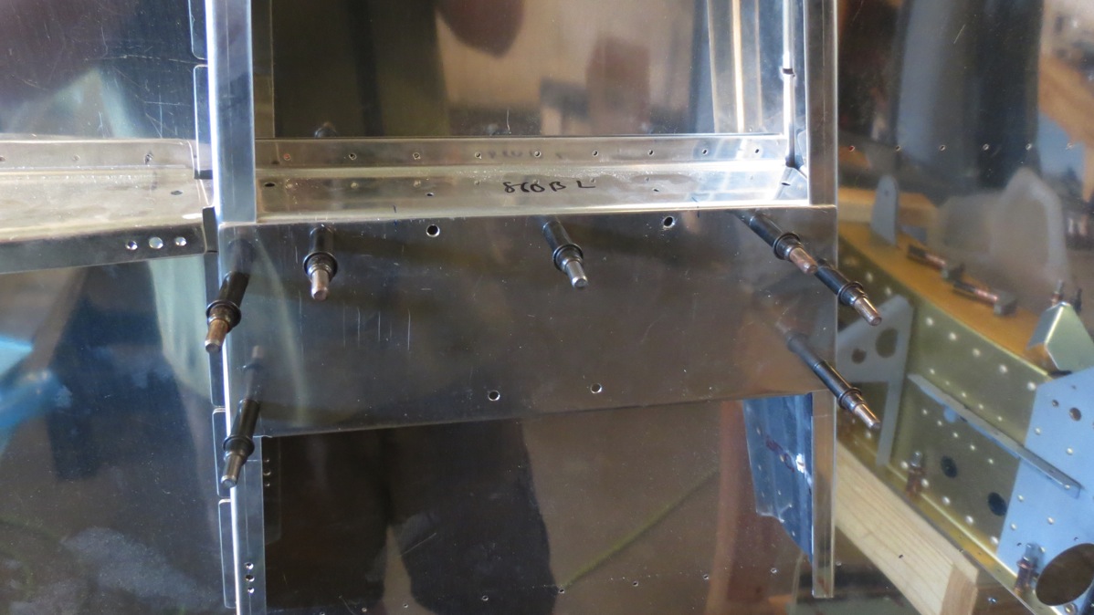
Here it is clecoed in position on the still-unmodified armrest:
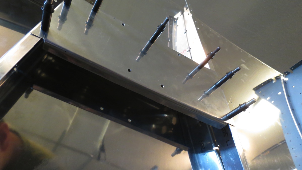
Here’s the flange I bent on the bottom edge:
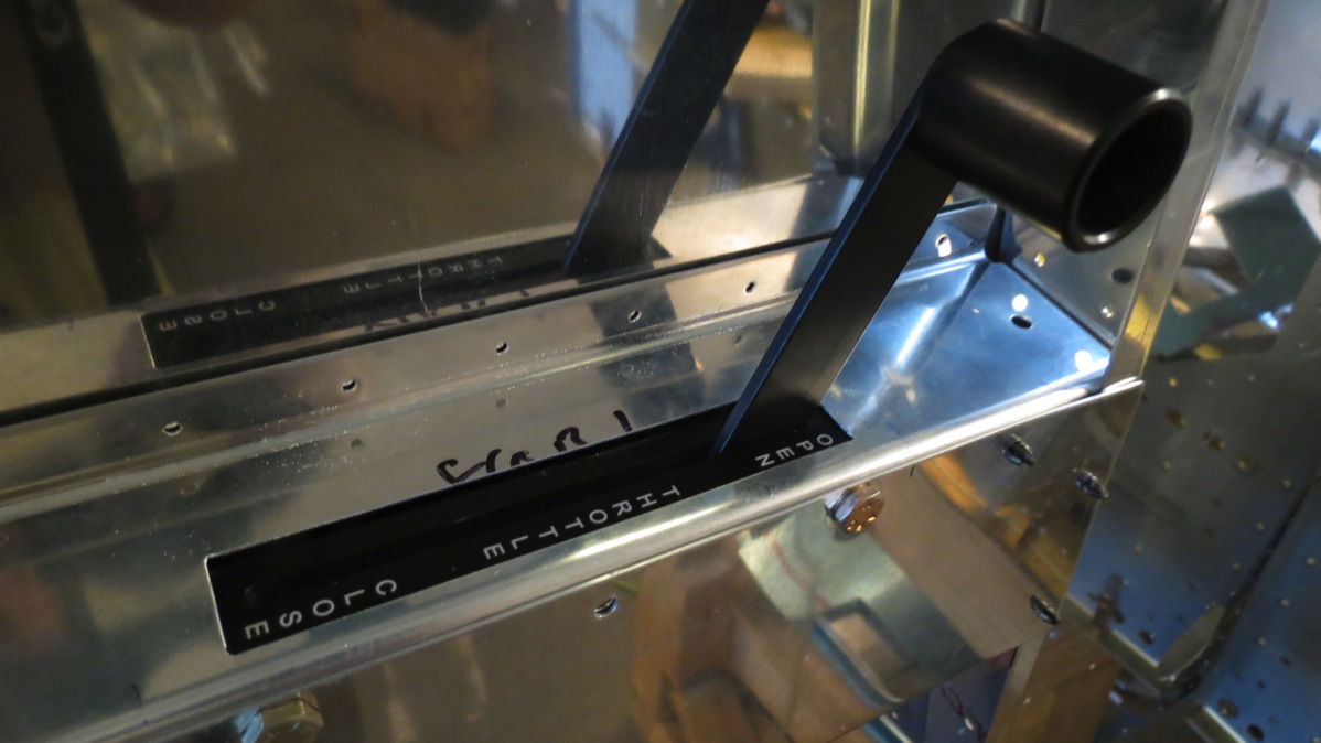
Next came the real fun: very carefully laying out the cut on the armrest. The throttle quadrant’s face plate sits beneath the armrest, so the desired end result is for the armrest to overlap the faceplate on all four edges (as opposed to leaving visible gaps), while of course leaving room for the lever to move. I also wanted to have the nice-looking markings on the faceplate visible. Needless to say, I took quite a bit of care in laying out these lines. I drilled holes at the corners to make a nice radius, then made the straight cuts with a cutoff wheel in the Dremel. That, in turn, was followed by a whole lot of filing to clean up the cut edges and move them out to the desired cut lines.
I was pretty nervous about messing the armrest up, but it ended up looking pretty nice:
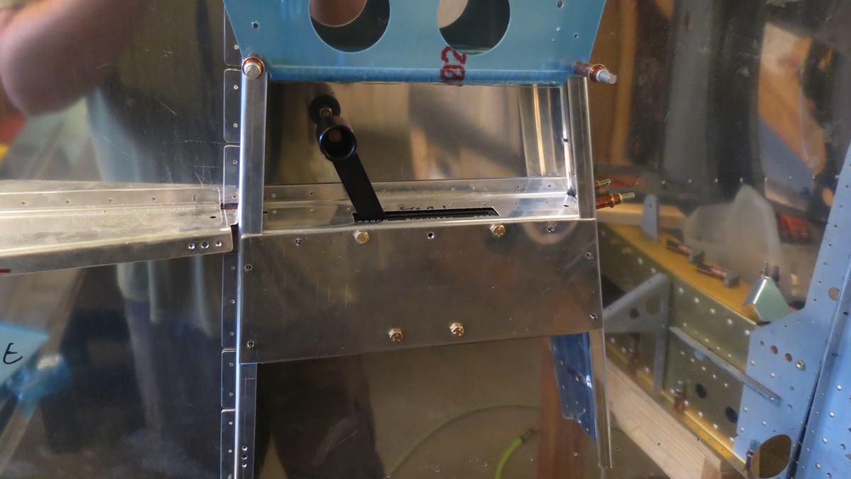
Here’s a wide view with the quadrant clecoed in place. I also clecoed the seat back support mounting plate to get an idea of how much clearance there’d be above the lever. The answer is “not a lot:”
I still wasn’t done, though. I discovered my first issue when I tried taking the throttle out. The armrest will be riveted in place, so removal of the quadrant will be accomplished by removing the throttle grip, then the screws holding the mount plate in place. At this point, the idea is for the quadrant and the mount plate to come out as a unit. Problem is, those upper two bolts go through the flange of the armrest. I’d cut slots there so the bolts would be able to slide out, but with the bolts tightened, they were still clamping the armrest flange. Well, that’s an issue.
What made it more fun was that I was using some washer stacks on the bolts to move the throttle outboard. The main reason for this was to account for the radius of the armrest where the flange is bent. If I had cut slots large enough to accommodate the washers, they’d be visible above the mount plate. Not a huge issue, but I didn’t like it. So I decided to replace the washer stacks with spacers made from some leftover aluminum tubing; these would be smaller in diameter than the washers and also be less annoying to deal with. But here I kind of fouled up. I had two short pieces of tubing left, one of which was barely long enough to make one spacer. I used that piece for the first spacer, then went to grab the second piece for spacer #2. This piece of tubing took a lot longer to cut, which I found bizarre. Then, when I compared it to the first spacer, ti was wider. Wait, did I have two different sized of tubing? Then I figured it out. I had’t cut my second piece of tubing, I’d cut one of the aluminum spacers that came with the throttle quadrant itself. Well, that was pretty stupid. I have some more tubing coming in my Spruce order, so I guess I’ll be cutting replacement spacers for the bottom of the quadrant as well.
In the meantime, I cut spacer #2 (using the correct piece of tubing this time), and marked and cut the enlarged slots in the armrest:
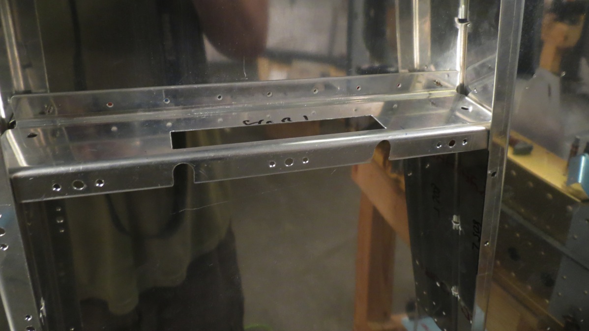
Initially, I’d decided not to bother cutting lightening holes in the mount plate. But then I realized that installing or removing the quadrant would require working behind the plate to connect or disconnect the linkage to the forward throttle. With that in mind, I decided that lightening holes would be a good idea after all, since they could also serve as access holes. So off came the plate again, and I laid out and cut two lightening holes:
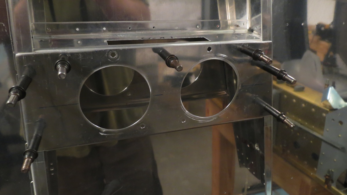
At this point, I finally considered the rear mount to be complete. So I moved on to worrying about the holes I’ll need to make in the bulkheads for the linkage. With the rear throttle quadrant faceplate bolted in place, it was easy to use the slot for the handle to draw an extended centerline forward on the armrest, then transfer it to the bulkhead and extend it downward. So now I have a reference line for the lateral position of the throttle lever. The more challenging part is creating reference lines for the vertical location of the hole. For one thing, I don’t know for sure where the hole in the throttle lever will be. There’s a predrilled hole, but it’s at the same level as the predrilled hole in the forward throttle, and that hole will be used for attaching the actual throttle cable. So I know I’ll be drilling a second, lower hole in both levers, but I’m not 100% sure where yet. Another consideration is that there will be vertical movement of the linkage; it’ll be lowest with the throttle at idle or full, and highest with the throttle at the halfway point.
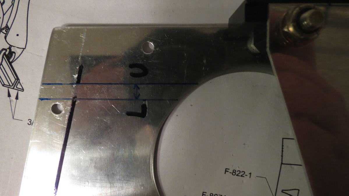
For now, I went ahead and drew two reference lines on the inside of the mount plate, using the existing hole location. Once I decide how far down to drill the second hole, I can simply shift these lines down by that amount, then transfer the to the bulkhead and work out the location of the pilot hole. I’m still not sure how I’m going to work out where to drill the holes in the center section bulkheads though…anyway, here are those two reference lines, showing how much vertical movement is expected from the linkage:
I also realized that I should have ordered some bolts from Spruce while I was at it. I’m relatively certain that I’ll end up shifting the forward throttle outboard by 1/4” or so by adding spacers. That means I’ll need longer bolts for the quadrant – which I knew, but I figured I’d have some longer bolts on hand I could use at least for temporary assembly. Wrong – the next longer bolts I have are a *lot* longer, to the point that I don’t think they’ll fit between the forward mount and the side skin. I don’t really want to go placing yet another order with Spruce and paying shipping on a stupid small order like this. Actually, it occurs to me as I write this that I could just get some hardware store bolts for temporary assembly, and put the proper AN3 bolts on my shopping list for later. I’m trying to get in the habit of maintaining shopping lists for Spruce and Van’s, so that I can delay non-critical items until I run into something that I need soon, at which point I can combine it all into one order and save shipping.
Anyway, that’s enough blathering for today. Hopefully tomorrow I can settle on the new pivot point for the linkage and at least drill my first pilot hole in the bulkhead, then try and work out the rest of the layout from there.