Welp, this was one of those days where you kind of step backwards in order to move forward, or something similarly zen. I did get the conduit ordered from Amazon, and it did go out for delivery today, but via USPS, and they held it at the office, which means I won’t have it in my hands until Monday at the earliest. I may actually wait until Tuesday, as I also have my antennas coming – I ordered those from Delta Pop Aviation Thursday evening, and they’re already on their way.
So with that in mind, I decided it was time to bite the bullet and get serious about the fuselage. Which meant removing most of the assorted stuff I’d put in there over the past several months. The tail feathers came off and went back into storage, the roll bar and panel came out, all my cardboard avionics mockups got put away, the control column and elevator pushrods got put by the wayside…and now it’s back to just looking like a canoe:

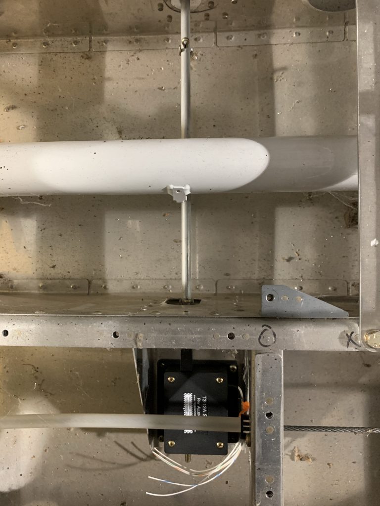
I also vacuumed out everything, which basically means I sucked up a whole ton of dead june bugs. Then I got the fuselage back into the rotisserie, and rolled on its side so I could look at the belly. Since the antennas are coming, I figure I’ll go ahead and get their mounting holes done once I have the templates in hand.
But first, I had to figure out where to put the antennas. There are four that I need to find homes for on the belly: two com radio antennas, and two blade antennas, one for the transponder and one for the ADS-B receiver. There are assorted placement requirements that kind of dictate where these will go. Specifically, the ADS-B receiver antenna needs to be at least 2’ from the transponder antenna, and the transponder antenna wants to be at least 3’ from any com antenna.
The com antennas should optimally be separated by 6’, but that’s simply impossible on an RV-8. Most small aircraft handle this by putting one on the belly and one up top, but there’s nowhere up top to do this. So the accepted thing for about every RV-8 I’ve seen is to put the com antennas just behind the main spar carry through, each one as far outboard as possible.
That means the other two get to go further back, and this is a segue into another consideration for placement: I want to be able to access these antennas relatively easily from inside the aircraft. That is, I don’t want them to live under any panel that’s riveted in place. The com antennas satisfy this, since they’ll be under the removable forward seat floor/footwell area. Further back, I have the rear seat floors and the forward baggage floor to consider; both of these will be riveted in.
This leaves two usable regions: the first is basically under and ahead of the rear seat, around where the rear stick is located. The other is aft of the baggage floor. Given the separation requirements, the most sensible thing seems to be to put one antenna in each region, and since the most confining requirement is the separation between the transponder and com antennas, that pretty much says that the transponder is going in the aft location.
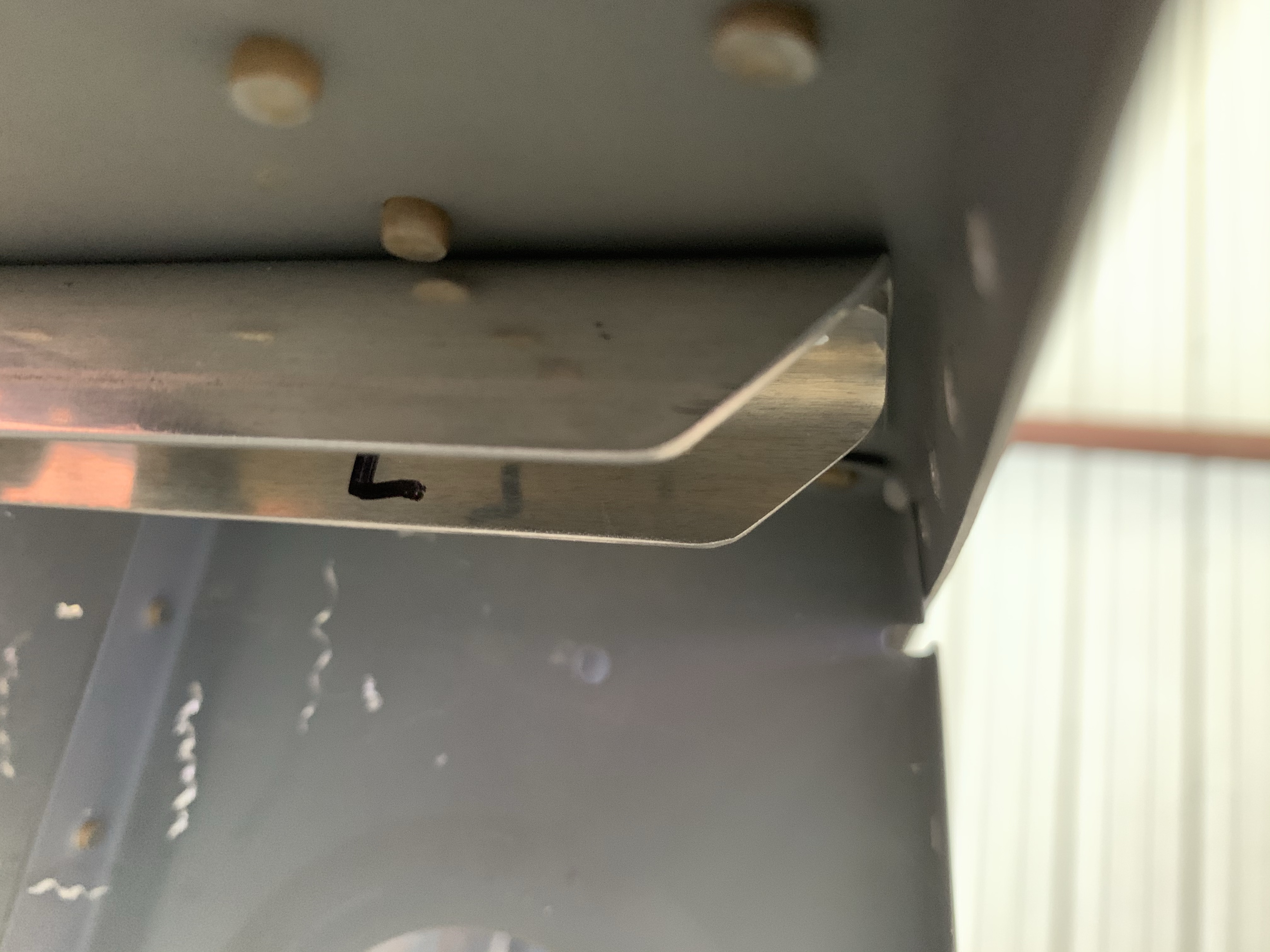
So with all that in mind, I made rough marks on the belly as to the location of each antenna. These will of course need to be refined before I can actually drill holes; I need to figure out how far outboard the com antennas can go, make sure they won’t interfere with the aileron push tubes, and similarly check for interference for the blade antennas. But this setup gives me a little over two feet between the two com antennas, a little under two feet between the com antennas and the ADS-B, a good 3.5’ between the ADS-B and transponder, and over five feet between the coms and the transponder.
Works for me.


So that’s it for today. I still need to put away a lot of the stuff I removed today, and then maybe I should review the riveting instructions for the forward bottom skin – that’s been deferred for way too long.