Good productive Saturday. I got started bright and early, marking the spacer pieces and their matching spots on the angles, getting the rivet holes countersunk, and then getting everything primed. I left the parts out in the sun to dry while going out for some errands – hauling off a load of recycling, and stopping by the hardware store in town to look for mount hardware for the ADAHRS. As I may have mentioned previously, these need to be attached with non-ferrous screws. My intent was to snag brass machine screws, which will definitely be non-ferrous, but the only things they had at the store in Brookshire were slotted head screws…and I really don’t ever want to wriggle back into the fuselage to remove an ADAHRS and then have to fight with one of those.
That left a couple options. They had some stainless Phillips head machine screws, which might be non-ferrous. Otherwise, I’d have to try the Ace hardware in Katy (probably on another trip) or just order some screws online. And I really wanted some hardware today, since I’d need it if I was going to finish the mount. Back to those stainless screws – all I needed to do was hold one near a magnet to see if it was attracted, but where to find a magnet? Fortunately one of the guys there figured that out for me – they had a big magnet used for picking up nails. And sure enough, no attraction for the stainless screws. Sold!
Back home, I got the spacers riveted to the angles, final-drilled and tapped the screw holes, and finally used my nice new screws to attach the units to the angles. This effectively meant I had a single mount unit, which I then took over to the fuselage to lay out the rivet holes with the longerons. Got those drilled and deburred, and that pretty much wrapped up the work I needed to do on the mount. I’m not going to rivet these in place just yet; I see no need to limit access back here right now.
I did decide to go ahead and install the fittings for the pitot/static/AOA lines, and get some layout done there. I went ahead and cut the three lines that tie the primary and secondary ADAHRS together, and also cut a new line to handle the routing from the static ports to the ADAHRS. That left the remaining pitot and AOA ports open, so to stave off any potential mud dauber mischief, I took another short piece of the static tubing (of which I have an insane surplus) and connected those two ports together.
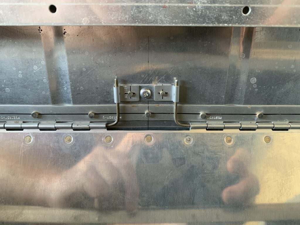
Behold the ADAHRS setup!

A slightly different angle, showing the static routing a little better. I think when I finalize this, I’ll add an adhesive zip-tie mount inside the skin, and use that to secure the line to the skin, rather than just having it hang out in midair.

With that bit done, I decided to move on to working on the right-side switch console. This started with just some generic experimentation – I had a general idea of how to do the panel cutouts for the switches, but some tinkering on scrap was definitely in order. Which was a good thing…for some reason, I had it in my mind that the panel itself should be drilled both for the switch center bushing and the anti-rotation washer tab. The latter is just a small second hole offset from the main one. I’m not sure why I thought that the switch itself would cover up that second hole, but that was definitely not a correct idea.
Some research inside told me that there were a couple different approaches to this issue. Some folks just did away with he anti-rotation washer entirely, depending on the star lock washer included with the switch and the nut torque to secure the switch. This seemed potentially reasonable, but also highly annoying to deal with during installation – I’m imagining trying to hold the switch straight while tightening the attach nut.
Another alternative was to have the anti-rotation tab hole drilled from the back of the panel, and not all the way through. This allows the tab to rest in the hole, with nothing visible not he outside. I liked this idea, but in my case the console material was nowhere near thick enough to handle this. So I decided to fabricate a backing plate for the switches, a piece of 1/8” thick aluminum stock that I’d drill for the center and anti-rotation holes. The actual console would only be drilled for the center holes. At first I figured I’d rivet the backing plate to the console, but then realized there was no reason to do this – the switches, once installed, would hold it in place.
So that took care of that plan – next up was to transfer the switch layout I’ve iterated on a million times to an actual part. I had to take into account part clearances here – for example, putting the forward most switch too close to the end of the console would cause it to interfere with the gear tower (which the console attaches to). So basically the first switch location was determined to address this issue, and everything else was positioned relative to it.
Another consideration is the the console is wider at the forward end than the aft. Since I’m using most of the length of the console, I have to be concerned about clearances at the aft end. I also have to worry about the angle on the side skin that the console mounts to. All this meant that I had to experiment a bit to figure out the lateral position of the switch lines. I ended up drawing two positioning lines, one 7/8” from the inboard edge and one 1” in. Then I laid out the fore-aft switch locations, and did some eyeballing to decide which position to choose.
The 1” line seemed too close for comfort to the angle, so I went with the 7/8” position. It’s also worth noting that while I’m calling the a switch console, there are also a couple circuit breakers and a PWM dimmer here. This is one reason why the marks shown on the following photo aren’t spaced equally. (the other is that there’s some separation between groups)

So after checking, double-checking, triple-checking, starting to drill and then going back to re-verify something, and so forth…I finally started center punching hole locations and got ready to drill.
The approach I took was to first drill #40 pilot holes in the console. I also laid out and drilled the first hole location in the backing plate; this let me cleco the two pieces together to get started match drilling. With the backing plate lined up properly, I drilled all the center holes out to #30, then to #12. I took this stepwise approach to drilling, as it let me correct hole locations along the way to try to get the best alignment. In the end, the alignment came out looking pretty good.
The next step was to drill the #30 alignment holes in the backing plate – no big deal – and then open the center holes up to 15/32” with a uni-bit. Well, not all the holes…the circuit breaker and PWM dimmer holes needed to be 3/8” instead. So I had to be careful to mark those holes and not get on a roll and drill them all to the larger size.
Since the pieces weren’t riveted together, I drill each piece individually. The backing plate went well, though I sure did make a bunch of aluminum chips. The thin console material would be a whole lot easier…and that attitude ended up biting me. Remember the part about being careful to mark the holes that needed to be 3/8” and not 15/32”? Yup, I drilled the PWM dimmer hole to the larger size. From a quick look at the dimmer, though, it seemed the nut would cover the larger hole…worth a try, so I kept on going.
With all that drilling done, it was time for some victorious temporary assembly work…but unfortunately, things got problematic from there. The first issue I ran into was the layout of the circuit breakers, which I didn’t really consider beforehand. With the way the circuit breakers are oriented in the panel, and the way their terminals are laid out, those terminals come really close to the side of the console. Since the airframe will be a ground, any contact here would be a Bad Thing. I suppose I might be able to heat-shrink over the terminals once everything was attached, but I wasn’t sure how I felt about that:

It turns out to be a moot point anyway. Once I tried putting the backing plate and the console together, I found that in the process of drilling the large center holes in the plate, a few of them had wandered a bit, probably due to me being a bit careless holding the piece in the drill press. The result was that the holes in the two pieces didn’t really quite line up. It’s possible that some careful filing might alleviate the situation, but taken alongside the other issues (the misdrilled dimmer hole and the breaker clearance issue), I’ve decided to junk these pieces and start over again. This effort gets chalked up as a learning experience.
This isn’t all bad. One side effect is that I can get more suitable material for the backing plate. The 1/8” stock I used is almost twice the thickness needed to accommodate the anti-rotation tab. Since I’m ordering from Van’s anyway, I can get some material that’s closer to the minimum required thickness – a little more weight saved.
This also gives me the opportunity to rework the console layout. The breaker clearance issue could be mitigated by shifting the switch line over a bit, but that gets me back into space issues at the aft end, so instead I’m going to rotate the breakers 90°. The effect of this, though, is that they can’t be in line with the other switches as before – they’ll need to be side by side. It’ll take some tinkering to see how that shakes out.
The real lesson out of all this, though, is that drilling the two pieces separately was a poor choice. For the next iteration, I’ll definitely be riveting the plate to the console, and that will happen before I start taking the switch mount holes up to final size.
So all in all, the day ended up a bit of a low note, but I’m not too bothered by it. Some things you just don’t figure out until you commit to trying, and this was one of those cases. Besides, I was about ready to order some stuff from Van’s anyway, now I’ll just add a few more parts. At least they’re pretty inexpensive.