Well, I’m still paused on the canopy front until I get in the replacement slide block from last week’s shenanigans, but in then meantime I get to kick off a whole new category with the first bit of firewall forward work. Most of the weekend has been spent working on other stuff around the house, but I wanted to keep making progress on something and so I decided to see about fitting the engine mount to the airplane.
The firewall and the structural bits behind it came with an existing pilot hole at each corner, and I drilled those holes out to 3/16” quite some time ago to allow for the fuselage rotisserie mount. The final bolt holes are 3/8”, but final-drilling those requires some attention, since individual engine mounts can vary even though they’re welded up in a jig.
So the first step is to do a rough evaluation of fit out of the box. To do this, I installed a couple of long AN3 bolts in the upper two holes and used those to loosely hang the mount in place. Doing this allowed me to establish a good starting point, as I could verify that the width of the two upper mount points were at (or very nearly) the same width as the two pilot holes. That meant I didn’t need to do anything dramatic to get those first two holes drilled…well, almost. The construction manual calls for drilling the holes using the engine mount as a guide, which I imagine helps ensure that the holes through the fuselage structure are in line with the actual mount sleeves. So the most interesting part of all of this was figuring out how to “clamp” the mount against the firewall. I probably should have gotten a photo of the final setup, which involved some ratchet straps going from a piece of lumber across the mount to the setback support in the cabin…
In any case, the upper two holes are now drilled and bolted in place. This gives me a nice base to work off of for the other two holes at the bottom:

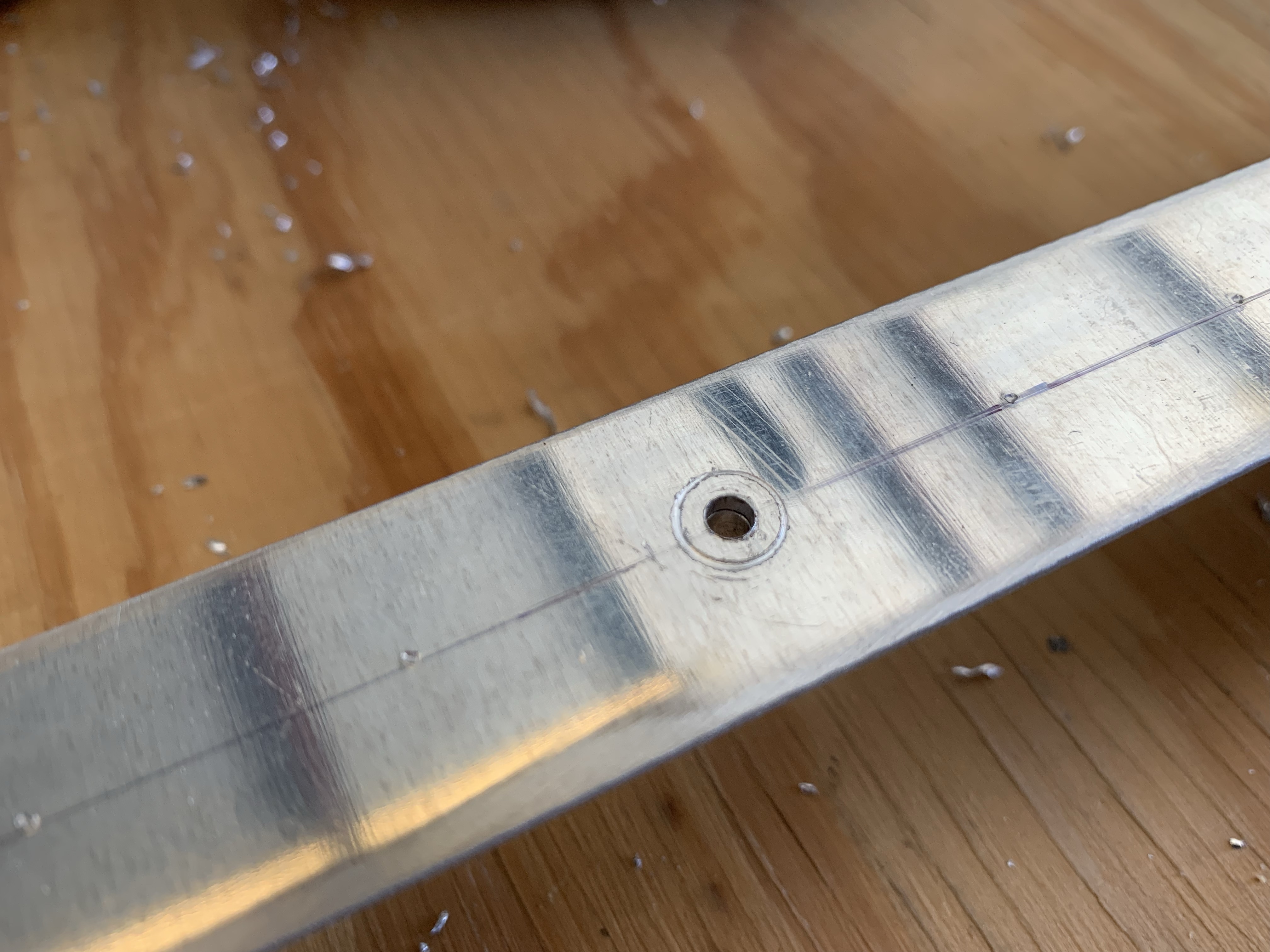
However, things down here are a bit less simple; the engine mount holes are a good 3/8” or so above the pilot holes in the firewall. I figured this out by putting flashlights inside the fuselage, pointed at the pilot holes; with that light sources inside, I can easily spot the pilot holes from outside, even if I’m looking through the engine mount itself. Note the pilot hole at the bottom of the engine mount hole, mostly occluded by the mount itself:

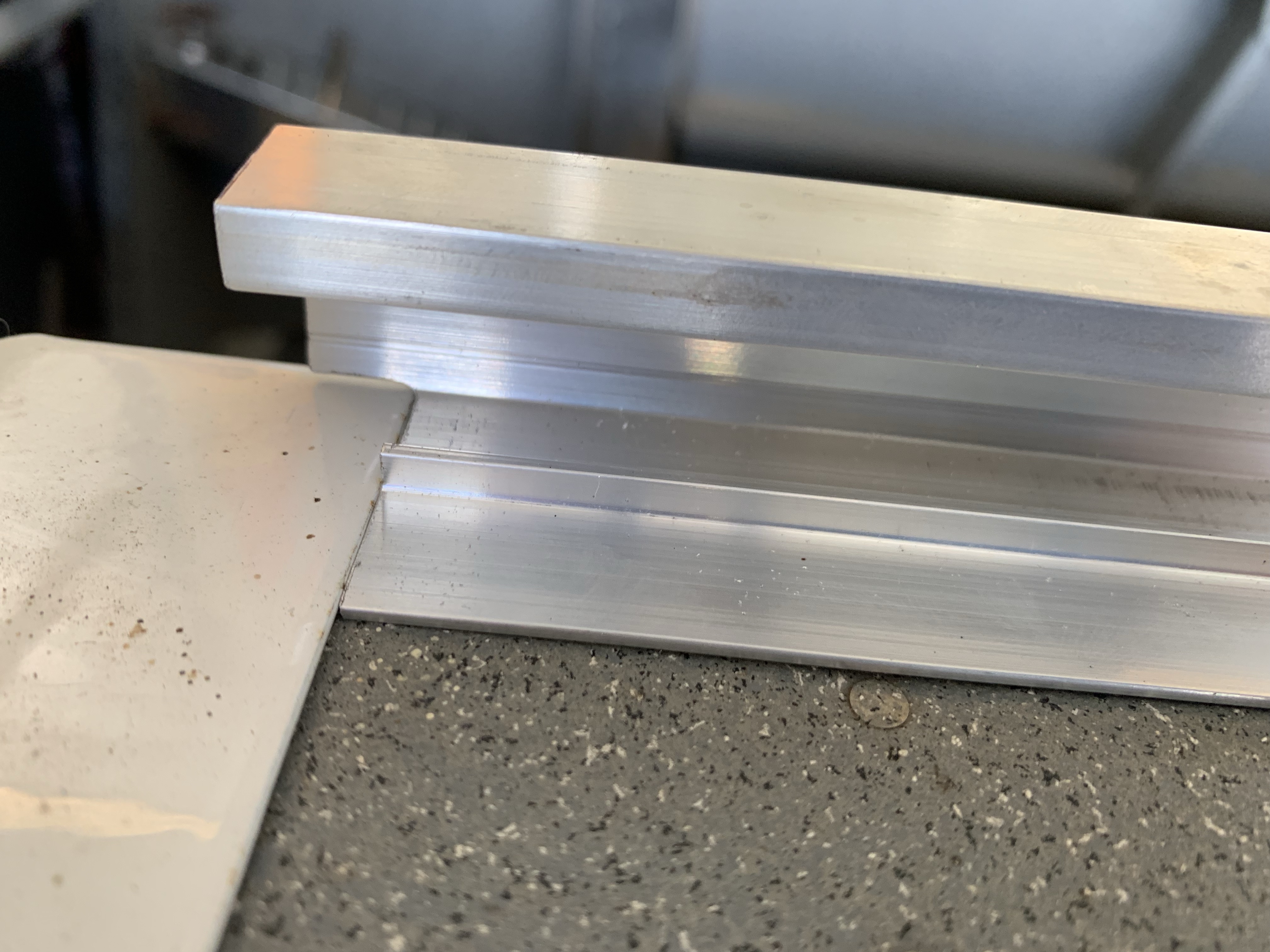
So in order to get these drilled, I’m going to need to rig something up to precisely stretch the engine mount. I made a first rough attempt at this tonight, which didn’t work so well. I figured since both lower holes are high, I’d see about trying to push both down, so I flipped one of my large hand clamps to make it into a spreader, and put it between the upper and lower center of the mount. I was able to move the lower holes by maybe 1/4” or so, but still nowhere near into alignment.
I’m not entirely sure yet how I’m going to work this problem, but so far I’ve had some vague ideas involving threaded rods, nut, and bearing blocks, but the hard part would be getting any of that stuff braced in the right place on the mount. Normally I’d prefer pulling for something like this, but I don’t really have anything to pull against…unless I were to put concrete anchors in the floor just for this one operation, and I don’t really want to do that.
So anyway, something to mull over. I’m sure it’s a solvable problem, I’ve just got to work it out.