Fuselage

Forward structure finished, moving on to center section

First order of business tonight was to get the firewall riveted to the forward floor. To start with, I cleaned and scuffed the mating area between the two pieces where I was going to apply fire barrier sealant. The prepping was probably overkill, but I figure it can’t hurt. NextI put down a strip of masking tape to help with cleanup later, then laid down a bead of sealant across the mating area. Note that this only covers part of the firewall’s width, specifically the area where the cooling ramp recess is located:

IMG 5936

Then I slid the firewall in place and clecoed it, making sure to put a cleco in every hole where there was sealant. These holes won’t be riveted until much later, so I’ll depend on the cloches to pull everything together tightly while the sealant cures:

IMG 5937

And finally I smoothed the squeezed-out sealant into a nice bead and removed the tape. There’s a bit of a gap in the fillet in the background of the photo, but the seal should still be OK. I’ll probably end up sealing this joint on the forward side just for extra security:

IMG 5940

Next, I worked on shooting the outboard rivets between the forward floor and firewall. These were kind of fun, because the firewall makes for somewhat awkward access for riveting. I eventually turned the entire assembly on end, with the firewall down. That made it much easier to shoot the rivets. The main issue here is that there’s no real structure between the top of the firewall and the baggage bulkhead. The baggage side piece keeps everything more or less in lien here, but there was one rivet where I needed to remove the baggage side for access. So I ended up using scrap wood to support the structure while the baggage side was out:

IMG 5943

That completes assembly work on the forward structure for now. Time to set it out of the way so I can work on other things. I’d been thinking about how to handle a platform to build the fuse on, and what I settled on trying was using my three good sawhorses, with a chunk of scrap MDF for a makeshift tabletop. Well, that was a decent idea, but that scrap MDF is way too short to be useful here. I need something more like a 8’x30” piece or something. I guess another Home Depot trip is in my future; the current makeshift platform barely accommodates the forward structure. There’s not even enough room to work with the seat rib assembly on this thing:

IMG 5945

Before quitting for the night, I tinkered with the center section a bit. Van’s support OK’d my proposed doubler to reinforce where I enlarged the wrong rudder cable passthrough hole, so I started working on that doubler. I cut a way oversize piece of .040” sheet and drilled the first batch of holes in assembly with the center section web:

IMG 5947

Next I’ll enlarge the proper hole for the cable passthrough in both the web and the doubler, then once that’s done I can work out the rivet locations around the perimeter of the doubler and ensure edge distance around the existing holes and so forth. Should be able to get this doubler finished up tomorrow night, I think…though my brother is coming to stay the night, so I’m sure it’ll be a short night in the garage, if I even get out there.

I should probably hash out the work platform this weekend, cause it seems like things are going to start going together fairly quickly here…

Posted in Fuselage | Hours Logged: 1.5

Center section repair and prep work

Started off this afternoon by continuing work on my center section doubler. I pulled the doubler off and used the unibit to enlarge the rudder cable passthrough hole to full size, then did the same on the center section web (the correct hole this time). Interestingly enough, when I clecoed the doubler back in place, I found that the two holes were slightly misaligned:

IMG 5950

But no biggie. I marked the overlap on the center section web and filed the hole out a bit until it matched up correctly. Next I removed the doubler again, laid out my rivet lines along the edges, drilled the holes, then clecoed it back in place and drilled the center section web to match the rivet holes:

IMG 5952

And here’s a look at the center section web with the doubler removed. There’s roughly 5/32” of material remaining between the two enlarged holes:

IMG 5954

With the doubler done, I moved on to general center section work. It took a few minutes to catch up on where I left off before. I’d finished match drilling the forward bulkheads, so tonight I did the same for the aft bulkheads. The assembly here is slight more complex due to the seat ramp supports and floor support angles, which rivet to the rear bulkhead. There are also two large vertical bars with 1/4” bolt holes that get drilled in assembly. So the evening was just a bunch of match drilling, countersinking nutplate rivet holes, deburring everything in sight, etc. At the end of the night I had a nice pile of parts ready for primer tomorrow.

Well, hopefully, that is, if the weather cooperates. I’d also like to make a Home Depot run for plywood for my work platform, but again, that kind of requires good weather. We shall see…

Posted in Fuselage | Hours Logged: 3.5

Center section finished

Whew…that was a good day’s work for sure. Started off this morning by cleaning and priming all the associated center section parts. That was a little bit tough…when I started cleaning the parts, it was bright and sunny. Halfway through, a random rain shower arrived. Fortunately, it didn’t last long, and soon I was able to finish cleaning the parts. Then another rain shower arrived. It was pretty obvious that leaving the parts outside to dry was unlikely to be successful, so I brought them in the garage. So drying took longer than usual, and then I had to shoot primer inside the garage with the door open, as the sporadic rain kept on coming. Finally I was able to close the door and get the air conditioner going.

After a break for lunch, the garage was cooler and I started riveting. The forward bulkhead assembly is simple, consisting of just three pieces. Didn’t take long at all:

IMG 5956

The rear bulkhead was more fun. For one thing, there are more components; here we also have the seat ramps and floor support angles, and then there’s my doubler repair just to make it more fun. It took quite a bit longer to get this together, working out all the different requires rivet lengths and such.

Here’s the completed doubler repair; it rivets partially in assembly with the floor support angle. Forward side:

IMG 5958

And the aft side:

IMG 5959

And the completed aft bulkhead assembly:

IMG 5961

Next up, I needed to fabricate spacers to simulate the wing spars. These are used to ensure proper spacing between the center section bulkheads during assembly. To be honest, I’m not sure these are needed for the prepunched kit. Some VAF research indicated that others felt that the spacers were a holdover from the non-prepunched kits. That same research also indicated that no one had actually tried building without the spacers. I guess no one wants to go to fit the wings after 1500 hours of work and find out they don’t fit. That’s pretty much the camp I found myself in.

I fabricated the spacers mainly out of some poplar pieces from Home Depot, with space in between to add washers and shims to get the thickness just right. Here’s one half of a spacer assembly with the shims in place:

IMG 5963

And with the second spacer half in place:

IMG 5965

And now the two bulkheads get assembled around the spacers. I initially used hardware store bolts with the threads ground off as locating pins (shown above), then replaced each pin with the proper NAS close-tolerance bolt once everything was together. Then I match drilled the common holes between the top flanges of the two bulkhead halves, pulled the halves apart to deburr and countersink the holes, then put it all back together yet again. As commanded by the instructions, this time I also bolted the seat belt lug, spacers, and control mount in place. This came back to haunt me once I started riveting the two halves together, because those bolts are in the way of squeezing the two inboard most rivets:

IMG 5966

So I got to remove those bolts (which I had just torqued about ten minutes prior), squeeze the rivets, and then put them back. Not too bad, but mildly annoying.

Anyway, that completes the center section assembly! On the bench:

IMG 5970

Clecoed to the forward floor assembly for safekeeping:

IMG 5972

And now it’s back to work on the seat rib assembly. Tomorrow, that is. For now, I’m tired and hungry.

Posted in Fuselage | Hours Logged: 7

Seat rib assembly match drilling

Not a lot of work tonight. My main goal for the evening was to finally go back and watch the 2015 webinar on flying into Oshkosh. The webinar was held the same night I was buying a car, so I couldn’t watch it live. But I did manage to get out and work for a little bit while waiting for Josie to finish up her work. First I just scanned through the completed steps for this subassembly, just to get familiar with where I’d left off – which was just after clecoing all the ribs to the rear spar carry-through and just before match drilling all those ribs. So I started off with that but of match drilling. The only interesting part was on the outboard most ribs; these have two 1/8” rivets and one AN3 bolt through the bulkhead. To hold the ribs in place while I drilled, I needed to insert a bolt through the bolt hole, but the holes in the rib flanges were slightly undersize, so I just had to drill those out. No big deal.

Next up, the two bottom skins get fitted to the bottom of the seat rib assembly. One of the skins has a stiffener angle bent into its inboard edge, but this leave the skin dead flat, whereas it needs to be curved to fit against the bottom of the ribs. Kind of hard to see, but here’s a rib assembly on top of the flat skin:

IMG 5974

The skin is bent by simply fluting that stiffener angle until the skin bend is acceptable. I was kind of surprised how heavily I had to flute here. The instructions say to flute every 1.5”, but in retrospect I wonder if it would have been better to put the flutes closer together and maybe not have to flute so aggressively. But then again, there might be a good reason for the spacing. Might as well just follow the instructions.

Next I flipped the seat rib assembly upside down and clecoed the bottom skins in place, then match drilled all the holes:

IMG 5976

And that’s where I left off tonight. Next I get to pull all this apart and do the whole deburring dance, but I think all this stuff will be going back together permanently in the relatively near future.

Posted in Fuselage | Hours Logged: 1

Seat rib assembly deburring

Ah, the drudgery part of building: deburring everything in sight. Tonight I removed all the clecoes I’d installed previously and went to town deburring. First I did the bottom skins; I cleaned the edges, deburred the holes, and then did some strategic rolling of the edges where there will be lap joints down the road. After setting the skins aside, I disassembled the ribs, angles, and so forth from the rear spar bulkhead and went to work on those. I’d hoped to finish all the deburring tonight, but I only got through the rivet holes on all those pieces. Some of the ribs had their edges done previously, but the bulkhead and some of the heavy bar stock pieces are still pretty rough. Guess I’ll pick back up with the edge finishing tomorrow night.

Here’s a photo of a big pile of parts:

IMG 5978

Posted in Fuselage | Hours Logged: 2

Seat rib assembly deburring and dimpling

Back at it again tonight. I spent most of the night deburring the edges of all the ribs and stuff. Mostly this consisted of running the bench grinder for about an hour straight, with some work with the vixen file and die grinder thrown in for good measure. Once I got all the edges taken care of, I dimpled all the appropriate spots on the ribs and rear spar bulkhead, then set aside and marked the handful of parts I want to prime. I even went ahead and cleaned and scuffed those parts tonight; I figure I’ll try and shoot primer on them first thing when I get home from work tomorrow night, then I can dimple the skins while the primer dries and maybe even get started riveting.

No pictures tonight; not really a lot to see to be honest.

Posted in Fuselage | Hours Logged: 2

Seat rib assembly riveting

Today, I went straight out to the garage after getting home from work, so I could go ahead and shoot primer on the pieces I cleaned last night. I gave them all a god acetone wipedown before priming since they’d been sitting out all night. Probably overkill (a repetitive theme in this blog), but just for good measure. I then took a break to install some cosmetic stuff on my car, then I retired inside to eat dinner while the primer dried.

After dinner, it was time to start putting stuff together. First up is the rear spar bulkhead, just riveting the carry through bars, the corner gussets, and the rear center seat belt anchor in place:

IMG 5981

Next the forward side seat belt anchors go together:

IMG 5983

And then it’s time to rivet the floor angles to the forward inboard ribs, along with the seat belt anchor assemblies and the little corner angle pieces I made a while back. This is where most of the night went; there are multiple rivet callouts to keep track of, various pieces to get aligned, and plus I accidentally shot a couple rivets without putting a needed piece in assembly, so I took care of my evening rivet drill-out quota right there.

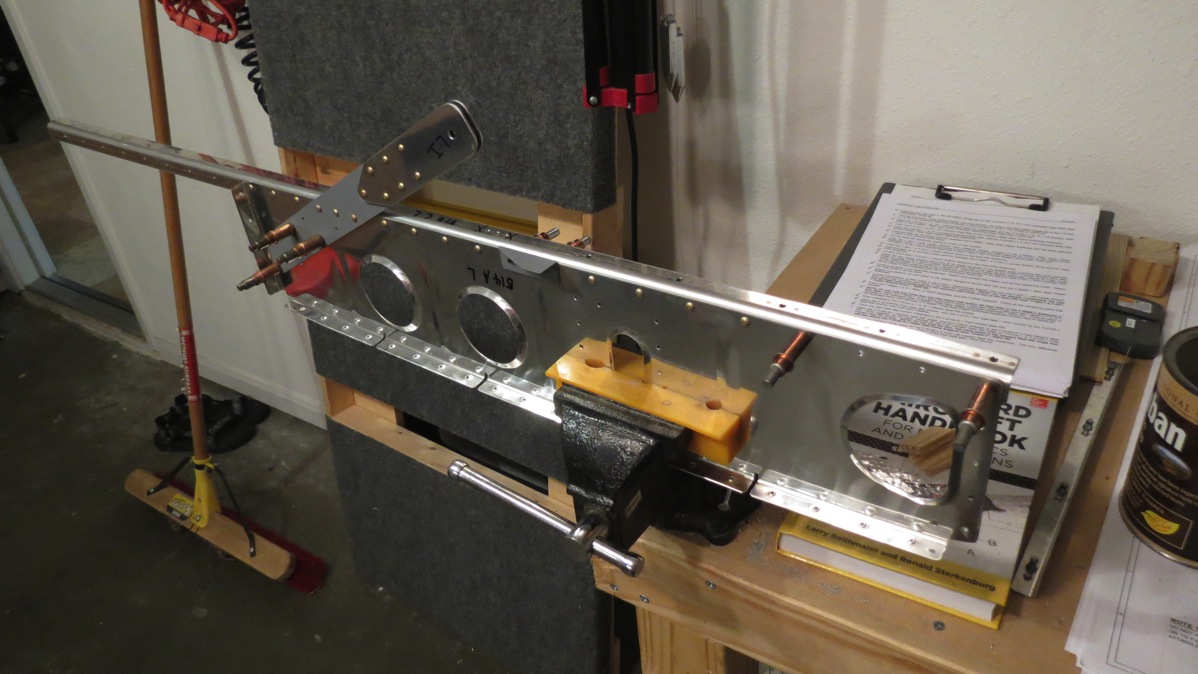
Here’s the left rib assembly in the vise while I’m riveting:

IMG 5986

For my final act of the night, I clecoed the two rib assemblies to the rear spar bulkhead along with the corresponding aft seat ribs. The next task will be to get these guys riveted in place:

IMG 5988

It does occur to me that I need to rivet the aileron trim bits to these ribs as well, but I don’t think there’s any special hurry on that. The trim kit is designed to be installed on a complete aircraft, so I don’t think I really need to stress about getting the stuff riveted before I move forward with the rib assembly. I’ll think it over overnight and probably look at the trim kit instructions before deciding what to do next.

Posted in Fuselage | Hours Logged: 2.5

Seat rib riveting, longeron bending

Whew…another good, productive day. I started out by continuing with riveting on the seat rib assembly. First the floor angles get riveted to the ribs, which is easy with the squeezer. Then the forward and aft ribs get riveted in assembly with the rear spar bulkhead, which is way more fun. The top and bottom rivets are easy enough, the middle two not so much. You see, the seat belt lugs on the forward ribs get in the way of bucking those two rivets. It would have been a lot easier to have riveted the seat belt lugs to the ribs after riveting the ribs to the spar, but I was just following the directions. Anyway, I managed to get the lower of the two annoying rivets shot without too much trouble: (the assembly is upside down in this photo)

IMG 5991

For the other pair, I decided to use MSP blind rivets in place of the solid rivets. I would have done this for the other pair as well, but those rivets go through the spar bars and so there’s far more material thickness, enough that I don’t have any appropriate blind rivets around.

IMG 5992

Next, I moved the assembly to a pair of sawhorses, clecoed the bottom skins in place, and went to work riveting them. This was a bit awkward at times, but not too bad. Here’s the finished assembly: (note my markings so I know what not to rivet yet)

IMG 5994

That completed the seat rib assembly, so next I moved on to the real fun: bending and prepping the various longerons. There are three pairs of longerons that get bent here; the lower forward longerons which run along the forward floor from the firewall to the center section, the auxiliary longerons which also run from the firewall to the top of the center section, and the 16’ long main longerons which I believe run all the way from the firewall back to where the tail mounts.

Each lower forward longeron already has a bend preformed in its middle; I get to add a twist on the forward end, then the rear angle is opened up, and finally the rear end gets twisted as well. Twisting is performed by clamping the longeron in the vise and grabbing the end with a crescent wrench and applying some muscle. I used my digital level to measure the bends; here it’s showing the pre-bend state of one of the lower longerons:

IMG 5996

Opening up the rear angle is fun. Basically you put the open end of the angle on a hard surface and then beat on the vertex of the angle with a big hammer. (Actual line from the instructions: “If you cannot get the angle to change…get a bigger hammer”) It takes a pretty impressive amount of force to open the angle. I was taking full swings with my deadblow hammer. I got Josie to come out and take some photos, since it’s been a while since I added some “prove you built this thing” pics.

IMG 6004

And twisting the aft end of one of the longerons:

IMG 6009

The auxiliary longerons are easier; they just get a gentle bend added to one side. This is done by marking the longeron at ~2” intervals and progressively clamping the longeron at each mark and giving it a good whack (that’s the technical term from the instructions) with the hammer. Then we move on the real fun, the main longerons. Each longeron has two bends in it, and both bends are made in two dimensions; that is, down and inboard for the forward bend and up and inboard for the aft bend. It’s still just a matter of clamping the longeron in the vice and assaulting it with a hammer, but given the length of these things, I was forced to turn off the A/C and open the garage door:

IMG 6011

I’ve seen builders seem to stress about these bends, and I suppose I can see why: if you ruin something, you get to pay shipping for a 16’ long box, which can’t be cheap. Hoever, I found making the bends to be pretty straightforward. There is an element of trial-and-error due to the two-dimensional bends; bending in one dimension tends to change the bend in the other dimension, so there’s a lot of back-and-forth until everything is right.

Of course, since the first longeron was fairly easy, I got complacent with the second one. I clamped it in the vice so I could measure and mark the bend lines, then went to town bending…only to realize I hadn’t moved the longeron so the bend line was in the right place. Yep, I bent it at the wrong spot. Fortunately, I was able to straighten the misbend and then get everything fixed up properly. I wanted to take a photo of the completed longerons, but it turns out it’s tough to take a good photo of something 16’ long and 3/4” square.

I was about ready to call it a night at this point, but I wanted to read ahead in the instructions and see what came next. I’d kind of figured that I’d move the forward fuselage assembly and clamp the longerons in place to kinda sorta store them, but it turns out that the main longerons don’t actually get installed until way down the road. So now I’ve taken two long angles that I had stored nicely, and bent them to where they’re way more annoying to store. I ended up cutting a few pieces of paracord and hanging the bent longerons from the garage door tracks right beside the other long angle stuff.

From this point, it looks like I get to fit the lower and auxiliary longerons to the forward fuse, along with some additional structure for the center section and gear towers. Guess I’ll find out about that stuff tomorrow night…

Posted in Fuselage | Hours Logged: 6.5

Reinforcement plates and whatnot

First up tonight were some reinforcement plates for the center section. These will (presumably) go under the skins at the center section to provide some additional structure and help distribute the loads from the main spar carry-through. These plates are provided as flat stock, but they need to be bent to match the curve of the bulkhead ends. Before bending, I went ahead and filed and polished the edges of the plates; easier to do that when the stuff is relatively straight. Next I set up the bending jig, basically just a pice of lumber set on 1/8” spacers and clamped to the bench. The plate is bent by slipping it under the lumber and applying downward force. By doing this at ~1/2” intervals in the upper part of the plate, the result is a nice gentle curve.

The bending jig:

IMG 6020

Next up are similar reinforcement plates for the gear towers. Here again, these plates will go under the side skin, and here again, they need to be bent to match the curve of the upper fuselage. These were made if thicker material than the center section plates, and thus bending them was a little more work. Always fun trying to balance “this takes a fair amount of force” with “no don’t put a big crease there.” After this, there’re two gussets that go at the top of the center section area to help tie it into the upper longeron. Once again, these guys need a curve bent into them.

Finally, after lots of filing, polishing, and bending, I had all these various pieces clecoed in place. Which is probably not strictly necessary, as I’ll soon be fitting the longerons under some of this stuff, but it’s as good a place to store the parts as any, I guess.

IMG 6025

And that’s it for tonight.

Posted in Fuselage | Hours Logged: 1.5

Lower left longeron fitting

Started out tonight by finishing up some work on the upper longeron gussets from last night. The tabs on the gussets need to be radiused a bit to clear the center section bulkhead, so I took care of that. Another issue I noted was that the spaces between the tabs weren’t quite deep enough to clear the flutes in the bulkhead flange. So I marked a line on each gusset and opened the spaces up a bit to provide proper clearance.

Tabs marked with the required clearance line:

IMG 6027

Next I separated, radiused, and deburred four more little gussets that will attach the lower and auxiliary longerons to the center section assembly. Then it was time to move the whole forward fuse assembly onto the workbench and get to work fitting the lower longerons. This is kind of fun; since the longeron isn’t prepunched at all, it has to be carefully fitted and clamped in place. I ended up clamping the thing in place three times. The first time the lineup was off and I had to start over. The second time I realized that I wasn’t going to have sufficient edge distance at the aft end of the longeron, so I removed it and marked the ends of both longerons to show where it was safe to drill:

IMG 6030

Finally, the third time, I was satisfied with the alignment…after checking it all about ten times. I ended up with, well, a lot of clamps holding it all together:

IMG 6032

Thenm after checking everything a few more times, I got started drilling. This is kind of fun since you have to drill up from below, using the prepunched holes in the forward floor as a guide. This, in turn, means that you get a ton of aluminum shavings raining down on you, along with hot steel chips in the couple of places where you drill through a weldment as well. Fun times!

But eventually, it was done. Well, at least the part where the longeron is drilled to the floor. There are still a couple other spots to drill, but I’ll pick back up on that next time out. In the meantime, here’s the aft portion of the longeron clecoed to the floor:

IMG 6033

Posted in Fuselage | Hours Logged: 2