Today wasn’t quite as productive as the previous week has been, but I think that’s OK. Some of that was just relaxation, but there was also some other work to be done around the house. Still, I managed to get over the sort of chaos hump and I’m now on the road to order. I think…
Things again seemed deceptively simple today, with just a few items left to close out. And true enough, most of it was simple; four wires to the Skyview GPS, split to both displays, a dim control lead from one display to the intercom…and then that pesky audio connection. To review, the Skyview system needs to output audio to the intercom; this is for assorted audible alarms, AoA indication, etc. What’s fun is that the install manual calls for the audio pins (left/right/ground) of both displays to be tied together and connected to the intercom.
As mentioned yesterday, normally a nice shielded wire bundle would be used here to avoid noise. But making a split circuit out of one of those would be interesting, and probably bulky in the harness to boot, especially since I’d want to figure out some way to tie all the shields together. I could skip tying the shields, but at that point why bother with the shielded cable at all? Maybe I should just run three wires and be done with it. But what if, in doing so, I condemn myself to a buzzy intercom (and/or the fun of trying to figure a fix after the fact)? I should just do the shield, obviously…but how do I tie it together?
I spent an absurd amount of time going round and round this circle in my brain. At one point I tried an idea of tying shield wire together at a single point (vs the window splices I’ve been doing). Can I fit two of these tiny wires into a D-sub pin? Nope. Hey, what if I strip one wire long, crimp the pin on, then wrap and solder the second wire just above the pin? Can I still insert it into the connector? Yes, but the soldered part goes inside the hole. Cal I extract the pin? Um…..no, I cannot. Well, not only is that idea a bust, but now I have a D-sub connector that’s unusable. Good thing I bought extra.
At some point it occurred to me to look at the prefab display harnessed I have. How did they do it there? I don’t recall seeing a shielded bundle in there. Yup, they just have the three wires in there, though they’re twisted together, which I suppose is sort of a middle ground between my two options.
Finally, I gave in and made a post on the forums. This was pretty classic analysis paralysis, I just needed some sort of shove in the right direction. And I got it…just one guy saying “use the twisted bundle, I’ve done this in several installs and it’s fine.” So I did that. I extracted the three-wire bundles from both my harnesses and did my usual window splice thing to tie them together.
At last, I had all the wires in there! Well mostly, I still have the CPI audio cable and tail light wire that’ll come in tomorrow, but…close enough for celebration, right?
I really wanted to move right on to starting some cable management, but I forced myself to stop and go through a QC check first. I wrote down every single branch on the whiteboard and went through every one and verified that I had the proper number of wires and that they at least looked right (ie power vs ground vs signal). If I’d wanted to be really thorough, I could have verified all the pin designations, but that probably would have taken a ton more time. Given that I verified each branch before closing it out the first time, I felt this was an OK compromise.
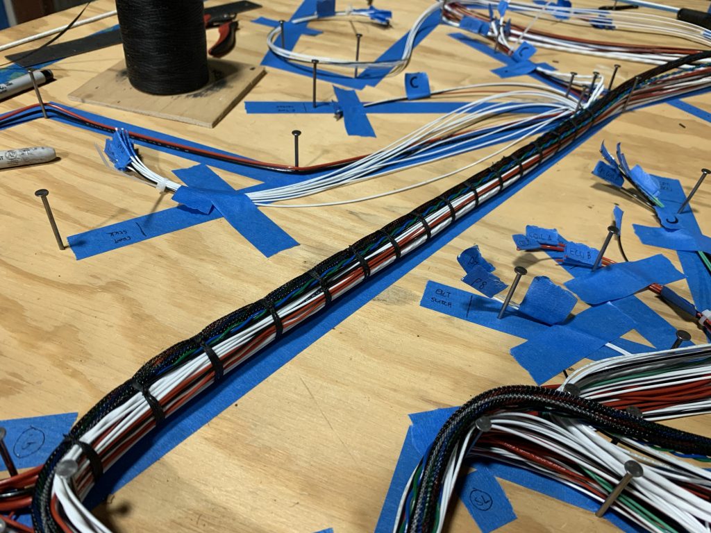
That meant it was time to get down to the real fun…starting to take this table of chaos and turn it into something orderly. Which meant breaking out the cable lacing and getting to work. I need to work out an overall strategy for how to approach this, taking into consideration the need to fish this into the fuselage at some point…but I’d at least thought this through enough to know that I was going to start with the wire run up through the right gear tower. In my mind this is the run that will anchor everything else.
Also, this bit of lacing made for a nice capstone to the day’s work…it sure is satisfying seeing things come together like this:
But that was the easy part. The next question is, how much lacing do I do on the table? Once these bundles are laced they become relatively inflexible, which 1) will make fishing them through the fuselage more challenging and 2) be problematic if I lace them up and they’re bent all wrong. And there’s at least one spot where my tape layout was a poor choice for preparing for lacing, right here at my Spaghetti Junction:
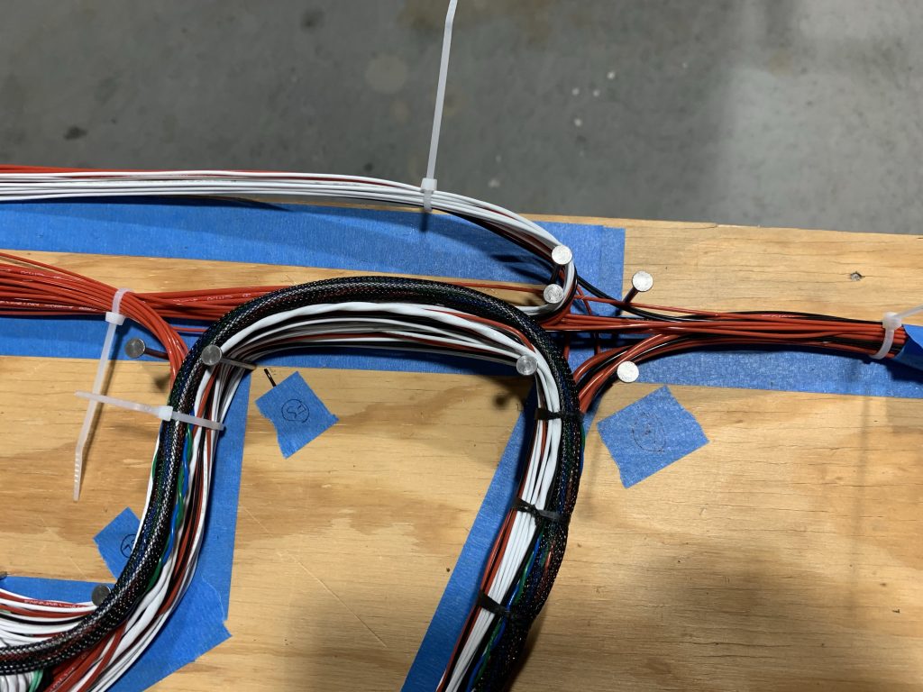
At issue here is the “crossroads” on the right side of the photo. This is indeed a four-way junction, but this orientation is wrong. The bottom branch in the photo will go down the gear tower and eventually aft, the upper one will go forward to the firewall, the right one will go aft to the switch console, and the left one will continue up before splitting between the fuse shelf and avionics shelf/panel.
Basically, I need to figure out some way to rearrange this junction before I lace anything else around it. Which will be fun, because it means rearranging a complicated branch, regardless of whether I decide to move the aft branch or the one going to the avionics shelf/panel. So far the best idea I have is to start working through the aft portion of the harness – I have to work out how to bundle this to go through the spar and conduit anyway – and if I can get that all bundles up in some temporary fashion, I think I’ll be able to see about moving it as a unit to get this intersection reworked as needed.
Yeah, we’ll see how that goes.
There’s also some prep to be done in the fuselage for running this stuff. I need a hole in the gear tower going forward for the FWF bundle, and I need to cover the edges of some other holes in the gear tower the bundles are going through. Those holes are too big for snap bushings, so I think I’m going to take some of my ample surplus of nylon pitot line and turn it into a split edge protector.
Oh, and more decision info: previously I was intending on not really terminating anything on the table, but rather getting this thing installed into the fuselage and doing all my final trimming and terminations in there. The more I think about that, the more I don’t like it. That’s a whole lot of wire stripping and crimping while hunched over the fuse and/or working in a tight space (such as behind the panel). Some of this will be unavoidable – the stuff aft of the conduit run ones to mind – but at least that’s a relatively small amount of termination. I’m really thinking of all the behind-the-panel stuff.
So for now I’m thinking of actually pulling the harness through the spar and conduit, massaging all my various branches and trimming them to final length, and then pulling the harness right back out. That way I can do most of then tedious termination on the table. Given the importance of 1) making those terminations nice and 2) getting all the pins in exactly the right place, I think it’ll be worth the extra effort.
But that’s all several steps ahead. There’s plenty to do before I make those decisions. Which is what tomorrow is for.