Avionics

Look, an antenna cable!

Tonight I decided it was time to finally try my hand at some coax. I got Josie to help me temporarily install the transponder and ADS-B receiver antennas, so I could work on the coax for those. I started with the transponder, which is the easier of the two, since it has a pretty short run. I actually spent some time trying to decide how to route it, eventually settling for running it under the avionics shelf and then through a bulkhead lightening hole.

Now, I did do a coax crimp or two when I did the Sportair electrical workshop…which was maybe six years ago. So I did take a few minutes to go read up on the trim lengths again before getting to work, and in general I probably took about five times as long as necessary to get the terminations done. and in the end, all I did was that one cable for the transponder, but hey, it’s something…

A look at the cable going through he bulkhead. The white thing mounted on the side of the lightening hole is what the cable will be secured to when final-installed. Obviously I don’t want it chafing on the edge of that hole, and I also want to make sure it stays clear of the rudder cable:

A look at the overall routing from above. So far, the only place the cable is supported is at that lightening hole, but I think I want to add something at the forward edge of the shelf as well – I still need to decide exactly how I want to handle that. But at the moment the cable is just sort of dangling in midair, which I don’t think is really satisfactory, especially given the proximity to the rudder cable:

So maybe I can figure out how to secure that next time out. Then I guess I can look at the longer, more convoluted coax run for the ADS-B antenna. That one will have to be terminated and crimped inside the fuselage, which will make things a little bit more fun…

Posted in Avionics, Fuselage | Hours Logged: 1

ADS-B antenna cable

Tonight was the second and much longer of the antenna cable I had planned. Whereas the transponder cable just has a short run from the shelf to the other side of a bulkhead, this one has to run all the way to near the spar carry through and then back to just ahead of the rear spar. It could be made shorter, but I’d have to add another rear spar penetration hole and live with this cable not being accessible without removing the seat floors. So I’ve always been planning to route it through the conduit, even if it made for a longer run.

The other fun part about this cable is that I couldn’t just fab the whole thing up on the bench; one end of it had to be terminated in place. That wasn’t much of a deal, though, just slightly more inconvenient. Once I’d finished the terminations and tested the cable, I went ahead and secured it in the seat-floor area. Some of those nice zip tie pads keep it tucked against the seat rib, and then it’s laced into the wire bundle going across the bay. Everything ended up nice and tidy:

I’m a bit less satisfied with the aft end of the run, though. I cut the cable a bit long, figuring I could deal with slack back at the avionics shelf, but I’m not really liking how all the slack ends up back here. I’m probably going to re-trim this end of the cable and put a 90° BNC connector here instead of the straight one. That should eliminate the big sweeping bend here that would otherwise be a little tough to secure to my satisfaction:

I’ve still got to figure out how to secure the transponder cable from last night where it ducks under the shelf as well – so far I haven’t had any bright ideas on that one. Maybe a small piece of angle, riveted to the shelf flange, and with a couple holes drilled, could become a little zip tie mount pad. But then I’d have to think about the rivet heads possibly chafing the wire bundle…hmm. Oh well, more thinking to do there.

Posted in Avionics, Fuselage | Hours Logged: 1

OAT sensors

What to do next? I feel like I’m in a weird state where I have plenty of small things to do but somehow it’s hard to decide which to work on at any given point. Well, tonight that thing was the OAT (outside air temperature) sensors. The Dynon OAT sensors connect to the ADAHRS units; this is why I have two to install (one per ADAHRS).

I’ve been sort of thinking for a while about exactly where to locate these. Some folks really like to put them out on the wings, but I didn’t want to deal with the wiring to make that happen. Second-best choice seems to be back at the tail. In this area, there seem to be two locations that people use; the first is on one side of the fuselage, under the horizontal stab, the other is on the aft most bulkhead, so the sensors are inside the empennage fairing.

I kind of liked the first idea from the perspective of keeping the exterior of the aircraft clean (plus not drilling more holes in my skins), but there are a couple potential issues with that spot. The first is that as the name of the sensor indicates, it really is supposed to go outside the aircraft; the idea is to read the ambient air temperature. Arguably, the area inside the empennage fairing isn’t really getting warmed by anything, so the difference might be trivial in most aircraft, but I expect to have the tail painted a dark color, which means there’ll be a good chance of significant solar heating of this area.

So it seemed that outside was the place to go. Next question, where back here? My strong desire for symmetry made me want to put one sensor on either side of the fuselage, but I didn’t like the consideration of dealing with the wiring for this – specifically routing one pair of wires from one side to another, in a way that it wouldn’t have a chance of interfering with the elevator push tube, which will pass through here. So instead I just put both sensors over on the right side.

That just left making the holes; laying them out far enough down to be away from the longerons, and properly spaced apart. Next was feeding the wires for each sensor through the hole, then feeding the nylon washer and nut from the backside and getting the sensors snugged in place:

Then I fed the wires forward, where they’ll run alongside the elevator trim and tail light wires. A look at the backside of the sensors through the aft deck:

Then I got to re-lace the wire run I put together a while back, adding the OAT wires to the bundle:

Next up I’ll need to get these terminated at the ADAHRs units. Which is another decision point; both sensors came with a lot of wire, pre-terminated with micro Molex pins. So I have a choice of either retaining the full provided wire length, which means coiling up and properly securing several feet of extra wire, or trimming and re-terminating the wires…assuming I even have the micro Molex pins on hand. I think I do, but I’m far from sure, and I didn’t check before coming in for the night. I’m leaning towards the latter just because my desire for neatness will be offended by coil of wire just sort of hanging around.

Another thing I did tonight was to finally commit to removing my fuselage rotisserie fixture. After thinking it over a lot, I don’t think I’ll need to roll the fuselage over again, and I want to have access to the firewall so I can start working on stuff there. First and foremost will be getting the ground bus installed and doing all my ground wire terminations, but there’s also adding the wiring passthrough hole on the right side. Once that’s done, I can pull through the harness bundle, then feed the ignition coil connectors back through into the cabin, and finish lacing up the harness section that’s waiting on that bit.

All that is to say, here’s the first look I’ve had at the bare firewall in quite some time:

Posted in Avionics, Electrical, Fuselage | Hours Logged: 2

Let’s get grounded

Alright, time to start thinking big-picture. Electrical stuff is fun and all, but I need to start thinking about working on the canopy at some point. This matters because the brittleness of Plexiglass is directly related to temperature – the warmer, the better. Basically, I don’t want to find myself starting on canopy stuff when it’s getting colder outside (of course, “cold” in Houston is very relative).

So what I’ve been thinking is that I want to get most of the electrical stuff behind the panel done, and then pretty much pause that work and move on to the canopy. Practically, my general plan is to get the ground terminations done at the firewall, do a final inspection, and do the ceremonial first power-on of the panel. Once that’s done, then I’m going to break out the Plexi.

Tonight I was looking at the grounding. First up was getting the ground bus block installed on the firewall. This block provides a bunch of 1/4” tabs on the interior side for my individual grounds, and a big fat lug on the firewall side for grounding to the battery. Practically, mounting it is easy, but I’ve spent a lot of time worrying about inadvertently putting it somewhere that will cause problems down the road when I get to working on FWF stuff. But after a lot of studying the FWF drawings, I decided on a spot and did the deed tonight.

Interestingly, as provided the block only provides one usable mount hole, where the big ground lug goes through. I didn’t feel this was enough for secure mounting, so in addition to the main lug hole, I added a smaller hole at the other end, where a #6 screw and nut keep the thing from rotating. So now I have the bus block mounted in place:

Next up was looking at the routing of the big bundle of ground wires. I laced this bundle up on the bench a while back, but like a lot of the lacing work from then, things seem loose – the individual laces like to move around. So as I’ve done other places, I pulled the bundle out of the gear tower and re-laced the whole thing. With that done, I should be able to get it in its final routing next time out, and start doing some terminations. None of this will be too complicated, but there are a lot of wires, so I’m just going to be doing a bunch of trimming, labeling, and crimping. Plus there’ll be a bit of work figuring out how to secure the bundle, but I have a pretty good idea how I’m going to approach that.

Posted in Avionics, Electrical, Fuselage | Hours Logged: 1.5

More grounding prep

Just a brief session tonight. Earlier today I sola fantasized about getting all the ground terminations done tonight and powering things up before the weekend, but it didn’t take much looking out in the hangar tonight to realize that was hilariously optimistic.

I got the newly-laced bundle pulled down into the gear tower and through the hole towards the firewall – kind of a pain really since all the masking tape tags made it impossible to just feed the bundle through as a unit. Between that and feeding a snap bushing over the end of the bundle to put into that hole, the result was a pretty tangled bunch of wires that needed some attention.

Next I sat down with the label printer and went through all those wires, putting in the labels for them. Kinda fun keeping track of which of 30-some wires I have and have not typed in already. Plus there were a couple tape labels that I was no longer sure what they referred to, so I ended up referring back to the schematics a couple times, just to make sure I was labeling things properly. Then I printed out a loooong string of heat shrink.

Before I trim anything to length, I want to get an Adel clamp mount point into the auxiliary longeron, since this bundle will need securing. That’ll let me get the general routing of the bundle down pat, and then I can start thinking about trimming. It’s going to be fun doing this since the area between the gear tower and the firewall is a bit snug.

Posted in Avionics, Electrical, Fuselage | Hours Logged: 1

Grounding: securing the bundle

Another no-photo night, I’m afraid. I decided to work on making provisions for securing the ground bundle. I already knew I’d be adding an Adel clamp on the auxiliary longeron forward of the gear tower, but I was debating also putting one on the forward brace above where the bundle goes down into the tower. The latter would be similar to what I did with the larger bundle coming up out of the right gear tower; on this side, the bundle was much smaller, but eventually I decided I wanted it secured as well.

Getting the nutplate mounted on the brac was pretty straightforward, though it still required the angle drill and some other creativity. The longeron was a lot more fun – initially I thought about just drilling the screw hole and using a nut instead of a nutplate, but I really didn’t like the idea of needing two hands to get the thing secured, so I went with the nutplate mount here too.

Unfortunately I didn’t finish that mount. The aux longeron is kinda fun to work on since it butts against the curved forward side skin – this means getting a tool aligned with a hole can be challenging. I already knew I’d have to make the rivet countersinks by hand, but I couldn’t even use the long shaft with the countersink bit here. Eventually I rigged up a combination of a hex adapter, 1/4” socket, wobbly joint, and a few extensions. That worked but it seemed like it’d take forever. So I added an adapter and my T-handle wrench, which let me put more torque on the setup.

That turned out to be a bad combination – it was hard to keep the bit well aligned, but easy to overcome the resistance from bad alignment with the T-wrench. The result was that I snapped the tip off my countersink bit on the second hole, and that tip remained lodged in the hole. I worked on extracting it for a while but eventually decided that I was getting to the point of causing damage if I kept trying to force the issue. Hopefully revisiting this in the morning, I’ll have better luck.

Posted in Avionics, Electrical, Fuselage | Hours Logged: 1

Grounding: terminations

Started off today revisiting that countersink bit chunk that was tuck in the longeron hole. At first I wasn’t getting anywhere, but eventually instead of trying to drive the thing out, I got a fresh bit and tried using that to push the broken off part out from below…and it popped right out. Should have tried that a while back, I guess.

I still needed to finish the countersinking, but overnight I had a real forehead-slapping moment about this job. Yesterday I was trying to work out some really crazy ways of running the countersink bit by hand. I thought about trying to just run it in the angle drill, but was thinking of threading the countersink into my thread-hex adapter and then chucking that in the chuck adapter for the angle drill, and thinking that would all be too bulky. When I thought of it the way I just typed it, though, I realized my stupidity…I could just thread the countersink bit directly into the angle drill…duh. With that realization, I finished the countersinks and riveted the nutplate in no time, then got the adel clamp loosely attached, just to keep the wire bundle roughly in place.

Then it was time for some terminations. First was the short pigtail for the fuel pump – I’m using handshake splices for this connection. It occurred to me today that blade terminals might be nicer down the road, but I don’t have those in the right sizes, so handshakes it is. I needed to do the pigtail first because the fuel pump ground was the last wire to add to my bundle – I temporarily removed it while pulling the bundle through the gear tower. While working on this stuff, I also went ahead and laced the bundle up to and a bit past where the pump pigtail comes out.

Finally, there was nothing left to do but to start trimming and terminating the actual grounds. I got through eight of them (out of, I think, thirty-some) before calling it a night. These went pretty quickly, so I’m feeling confident about wrapping the rest of these up tomorrow – though there will be some pauses to handle lacing up the bundles. I want to go a little beyond just lacing the big bundle until it splits to individual ground tabs, maybe lace together batches of eight or so just to provide some vibration support closer to the tabs.

But hey, I finally have a photo again:

Posted in Avionics, Electrical, Fuselage | Hours Logged: 1.5

Grounding: DONE

Got a nice early start this morning before it got stupid hot outside. I managed to finish up all the ground terminations by 8:00, at which it was time to stroll across the runway for Sunday Coffee Club. That was followed by several hours working on a Helio Courier that was donated to the Waller County Aviation Museum. Finally, I got back out and finished up the cable lacing and securing in the ground bundle area:

 At this point, I decided it was time to work towards actually powering up the panel. There was still a decent amount of work to be done before that, mainly from a quality-control (read: avoiding release of the magic smoke) perspective. What I decided to do was to disconnect every avionics connector in the airplane, apply 12VDC to the fuse blocks (with fuses installed, of course), and probe every pin in every connector, confirming that only the ones that were supposed to have 12VDC had it. After all, I figured the most likely cause of magic smoke release was putting bus voltage somewhere it didn’t belong.

That bit of testing took some time and was pretty tedious, and I also did the same testing for good grounds, ensuring everything was kosher. I also built out coax cables for the com radio and GPS-175 – I didn’t want any chance of something being damaged by powering on with no antenna connected. But finally, I had the panel and avionics shelf in, everything in place, and the main bus block tied to the power supply. I looked everything over one more time – that’d be a lot of money to ruin – took a deep breath, and flipped the switch.

What I got was not what I expected at all. A couple units flickered on briefly, and one display showed a splash screen for a moment before going dark. Was this the normal boot sequence? Nope, another flash, another brief splash screen, nothing. This seemed indicative of periodic voltage drops from the power supply, and checking across the terminals with my multimeter confirmed it – the drops were large enough to be noticeable on a relatively slow-responding digital multimeter.

Strange – this was a 12A power supply, and by the book all the avionics together should draw under 6.5. But still, I started pulling fuses – maybe I just needed to shed loads a bit. I eventually got down to just the two HDX displays, but still got the same results.

A this point I gave up and went inside for dinner. After thinking it over, and chatting a bit on a phone call with my parents, I decided to try one more thing – bypassing the fuse blocks entirely, and trying to only power a single display. And here I finally had some success – the one screen was actually able to get through the boot sequence. Even so, the display was still flickering from time to time, so obviously this power supply is problematic.

At least now I know that both displays are functional. I didn’t get the full-panel “it’s aliiiiive” photo I was hoping for, but I guess one display lit up is still something:

So, where to go from here? I may see if a neighbor has a better power supply I can bother. I may also try adding a 12V battery in parallel to the power supply to try and smooth things out a bit – it’s not a perfect solution but maybe it can at least get me through some initial testing.

Posted in Avionics, Electrical, Fuselage | Hours Logged: 4

Avionics are alive!

Well, today I went through several levels of troubleshooting but it all paid off in the end. Working off the idea that my power supply wasn’t performing well, I decided to try adding a battery in parallel. At first I tried the small backup battery for the CPI2 unit; I removed it from the plane last night and let it charge on a battery tender overnight. This morning before work, I tried adding it in parallel – no change. I even tried powering the panel off the battery alone, to no avail.

In retrospect, this should have been a major hint as to what was going on, but I didn’t get it. Instead, I concluded the battery was too small as well, even though that seemed nonsensical since the ignition is going to draw significantly more power than a single EFIS display. So i extracted a battery from a motorcycle, gave it a good charge, and tried that after work. Same result again, which was really weird.

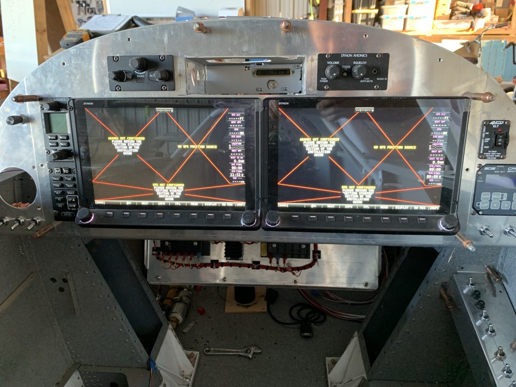
OK, next step is to take the aircraft wiring out of the picture. I took one of the original Skyview harnesses that I never used, removed everything except the power and ground leads, and connected those to the power supply. This time, the display booted up, and for a moment I thought I’d had a breakthrough…but then it started flickering again.

After a lot of head scratching – plus bouncing ideas off my neighbor, who’d come by to take my firewall rotisserie fixture for his -8 project – I really was suspecting the connections. Up until this point i’d been using some test leads I had with alligator clips on either end, since they were easy to install. To make a long story short, I replaced both leads with actual terminated wires, and finally I was in business:

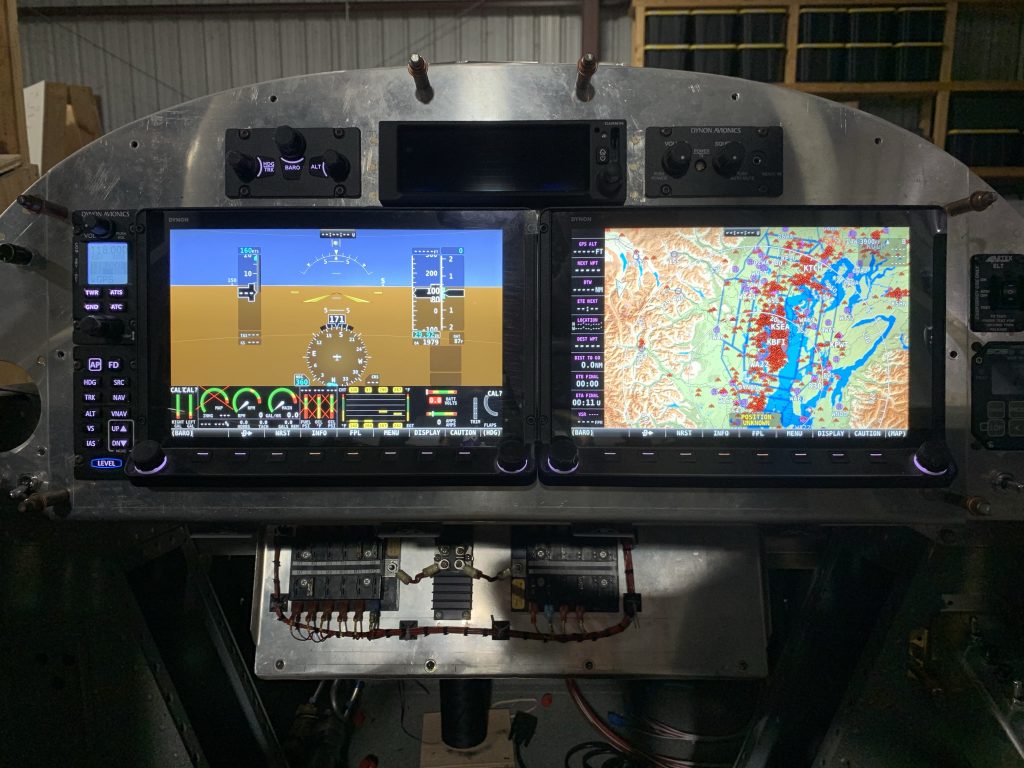
From that point, I started adding things back until I was powering both busses again, and I was able to get the entire Skyview system up and running. I configured all the network devices, got an initial hack at a display setup done, and generally just kind of sat there playing around with things. Lots of stuff isn’t going to be functional at this point – no GPS signal in the hangar, the engine monitoring obviously has nothing to monitor, and so on – but by god, it looks like airplane stuff.

The only rub here was the GPS-175, which didn’t want to power on. I reverified the connector pinout, made sure it had power/ground where appropriate, but still no joy. But when I connected the backshell to the GPS unit outside the rack, it powered up. Clearly there was a connection issue, but only in the rack.

Turns out that when I built this rack mount, I misunderstood how the mechanism for securing the unit in the rack works. I thought it was a simple locking tab, but it also has a threaded portion that mechanically pulls the unit into the rack. Well, even with the bezel of the GPS against the panel, the connector obviously wasn’t engaging. I’m pretty sure that, due to my misunderstanding of how the rack worked, I set it a bit too far back into the panel, so I’ll probably need to re-fabricate the angles that connect the rack to the panel.

I did go ahead and power up the GPS again outside the rack to try some configuration there. A nice VAF person sent me some information about getting the GPS properly talking to the Skyview units, and with his info, I got that setup done in under ten minutes; I was seeing message traffic from the GPS on the Skyview setup menu, and the GPS test mode was properly driving the Skyview HSI as expected.

So all in all a happy day. I guess now it’s about time to set all this aside and start thinking about working with the canopy. Only thing I still need to work out is routing the tail strobe wire out through the aft bulkhead, then I think I need to start getting the turtledeck permanently installed.

Posted in Avionics, Electrical, Fuselage | Hours Logged: 2.5

More avionics tinkering

Mostly sort of tinkering around tonight. I did decide that I wanted to try and verify a few more things before moving on to the canopy; basically this is me wanting to nail down components in the tail as much as possible before turning that part of the plane into a cave. The verification I wanted to do involved the transponder and ELT. Both of these boxes receive position info from the GPS-175 via serial data; for the ELT this allows for a more precise emergency transmission, while for the transponder the GPS-175 data is required for ADS-B compliance.

Of course, doing either one of these requires that the GPS-175 actually have a position. And while the Skyview system was eventually able to get a position fix even inside the hangar, I’d had no such luck with the 175. I decided to give that a try tonight, leaving everything up and running for over 30 minutes, and it still didn’t work out. That’s not too surprising, but kind of a bummer for testing purposes. I’m considering figuring a way to roll the fuselage out onto the ramp just so I can test this, but I’m not really sure of a good way to do it right now.

Anyway, while I was letting everything run, I did install the fuse for the transponder and get that set up with the Skyview system, though of course it complains that there’s no complaint position source. I also inadvertently verified that the ADS-B receiver worked, since I saw some traffic appear on the display while I was poking around at other stuff.

I also got to looking at the tail, thinking of routing the tail strobe wire. I temporarily reinstalled the elevator push tube so I could get an idea of potential interference, and I think I have a good idea how to approach this routing now. Originally I was thinking I’d have to route it through the forward bulkhead hole the push tube goes through, which was really bothering me, but it’ll be a lot smarter to just drill a hole in the bulkhead with a snap bushing – this should keep the wire well clear of the tube.

Posted in Avionics | Hours Logged: 1