More selector stuff

Aaaand here we have yet another instance of “seemingly simple things gone wrong.”

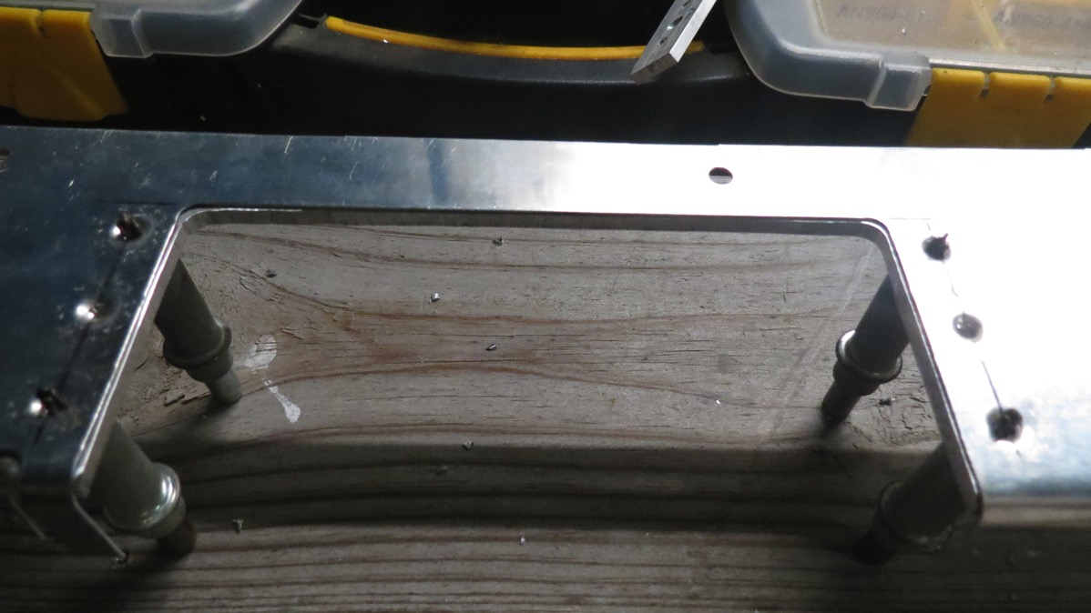
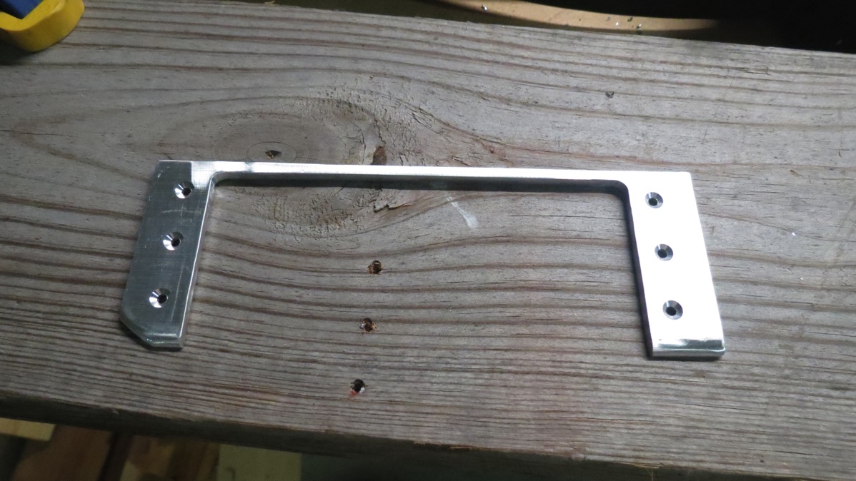
Tonight I had low ambitions; I figured I’d get the selector mount riveted together, temporarily mount it in the fuse, and fit the left mid-cabin cover and get the holes needed for the selector at least marked and maybe even cut/drilled. Doing the riveting wasn’t difficult, as one might expect, though it was a bit more tedious than I expected. (it takes some experimentation to figure out how to hold oddly-shaped parts steady for squeezing rivets)

The fun came when I screwed the selector mount into place. Here it is in all its glory (I clecoed the face plate on just so it’d look a little more like something):

IMG 7122

Now for the mid-cabin cover. Now, here’s the thing with these covers: They basically cover the trapezoidal area seen in the photo above, and mount with screws around the perimeter. The screw holes and nutplates are prepunched on the braces and the spar center section, but the auxiliary longeron (bottom in the photo above) needs to have to screw holes drilled. The cover itself has these holes prepunched, so you just temporarily attach the cover and use it as a guide to drill those holes.

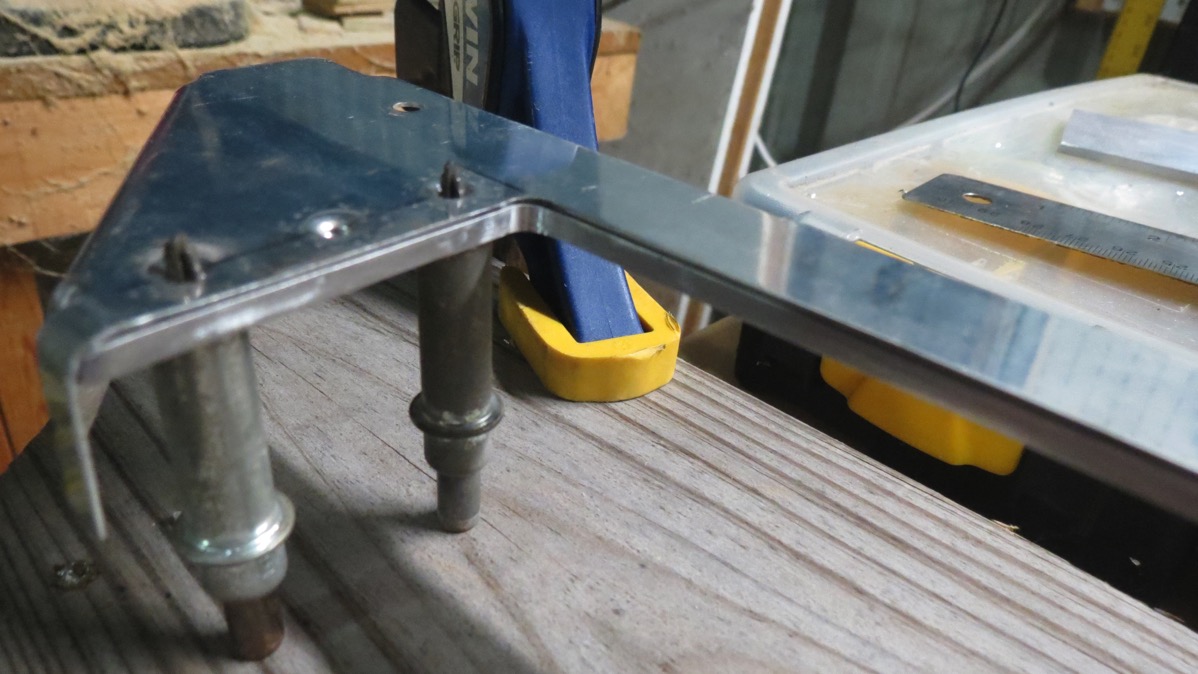
Except for one problem: it turns out that the forward part of my selector mount sits almost exactly where one of those holes has to be drilled:

IMG 7125

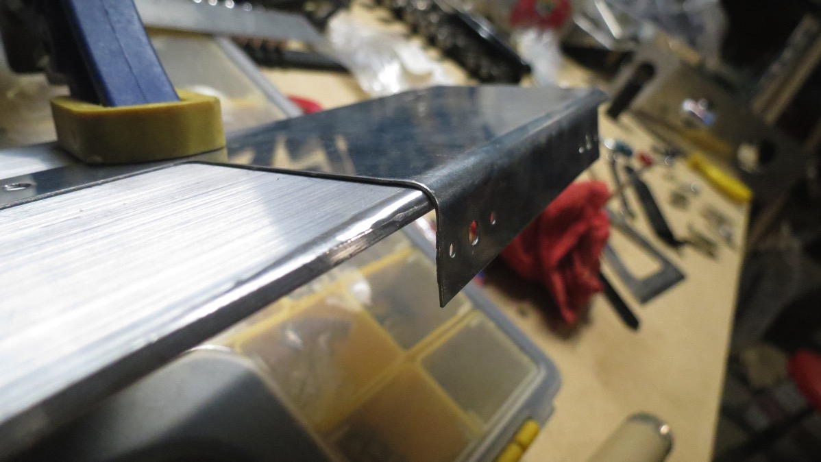
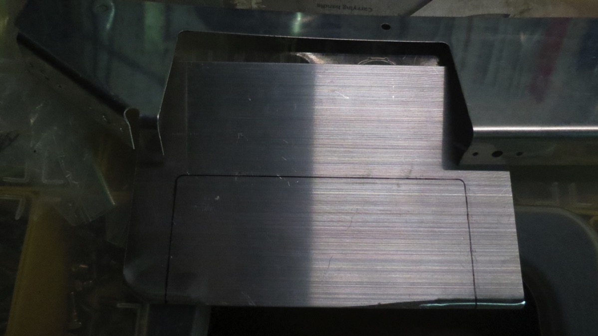
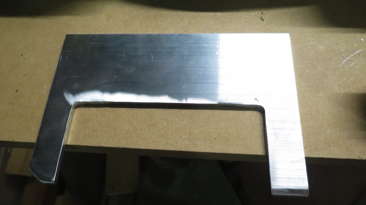
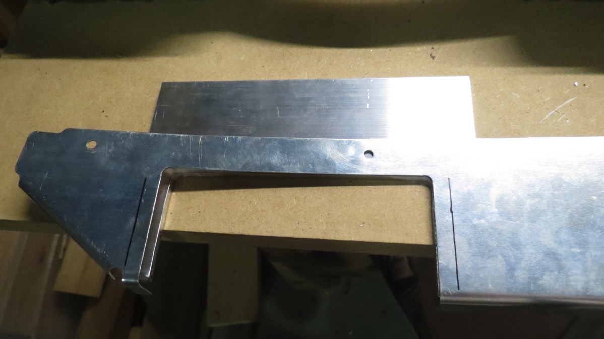
So long story short, I can’t use that hole location. Not really a huge deal though, I can just make a new hole in the cover an inch or two forward. But then if I use this prefab cover piece, there will always be that empty screw hole that probably only I will know is there. The good news is that I have material on hand to make a new cover; the covers are the same thickness as the leading edge skins, and I still have by damaged skin sitting around. I figure I’ll just cut a new cover for the left-hand side out of that. Shouldn’t be too hard, the shape of the cover isn’t especially complicated.

But that’ll be a job for another night. And who knows, by then maybe I will have decided that an extra open hole isn’t that bad after all. We shall see…

Posted in Fuselage | Hours Logged: 1

Selector mount priming, flap bearing block drilling

Not a ton of activity tonight, just trying to be doing something basically.

I cleaned and primed the parts for the fuel selector mount; well, the angles and spacers at least (no need to prime the alclad mount plate piece). I did the ghetto cleaning; that is, rather than scrubbing with degreaser, I just scuffed the pieces and gave them a good wipe down with acetone. I honestly considered not even priming these parts – they’re not going to be exposed to the weather or anything – but in the end the directive to prime everything that’s not alclad was irresistible.

Then I switched gears to the flap bearing blocks. Now that I had the blocks trimmed and drilled correctly, I fit the flap weldment into the blocks and put the whole assembly into the fuselage. The two rear bolt holes for the blocks are predrilled and already have nutplates installed, so I put bolts in those holes to hold the blocks in place. Then I drilled through the other holes to make the forward bolt holes through the floors and mount angles underneath. Later on I’ll get to drill for nutplates in this semi-confined space and rivet them. Should be fun.

Getting this done was made easy by my new tool I got from Cleaveland. I’ve had my angle drill attachment for ages, but one issue with it is that it only accepts threaded drill bits, which is kinda limiting. In this particular case, using anything but the angle drill would have been tough, and the threaded bits were nowhere near long enough to go through the bearing block and then into the actual stuff that needed drilling. But it turns out you can buy a normal drill chick that threads into the attachment, allowing you to use normal drill bits in the thing. Very handy.

Here’s a look at that assembly – also visible in the background is the flap weldment (the white powder-coated tube):

IMG 7120

Next up, I’ll rivet the fuel selector assembly, get that finally fitted into the fuselage, and then finally pick up with fitting the mid-cabin covers.

Posted in Fuselage | Hours Logged: 1

More fuel selector mount stuff

Welp, not the most productive weekend, but hey, I still did stuff.

All my various ordered came in, so I got the bandsaw up and running again. That allowed me to trim the corners off the flap bearing blocks, and since I also got the #10 drill bit, I was able to drill the bolt holes out to the correct size. I kinda stuck the flap linkage and blocks into the fuselage in place, but didn’t do any actual fitting – I wanted too focus on the fuel selector stuff.

On that point, I cut my 1/8” spacer pieces to go between the selector mount plate and the mount angles, got those drilled to match the plate, and then dimpled the plate and countersunk the spacers for flush rivets. I also countersunk the two screw holes I final-drilled in the mid-cabin brace last time out. Oh, and I fitted and drilled the holes for the nutplates in the selector mount angles that will accept the screws I countersunk the mid-cabin brace for.

While working through this stuff, I also got to thinking about how I was going to eventually actually mount the selector. There are three screw holes that go through the selector faceplate and the selector body. The body is already predrilled for nutplates. For some reason I had thought the selector would be screwed to the mount plate, and the large cover plate that covers the space between the aux longeron and mid-cabin braces would only have a hole for the selector shaft to go through. But the selector cover plates has to be on top (since it has the L/R/OFF/ indicators), so I guess the screws will go through all three pieces.

Anyway that left the question of what screws to use here. The holes are 3/16”; AN3 bolts would work here but seem like an odd choice. Maybe pan head AN screws, but I don’t have any of those lying around. I did find some flush head AN screws, maybe those would work. Hm, do I even want non-flush screws here? I assembled the selector and determined there’s room for the selector to move and not interfere with pan head screws, but hey, they might catch my knuckles or something. Eh, I’ll go ahead and use the flush screws.

So I countersunk the face plate for the screws, and riveted the appropriate nutplates to the selector body. Also – keeping in mind last weekend’s experience with “borrowing” hardware and then forgetting about it until way down the road when I needed said hardware – I decided to start a list of “borrowed” hardware. In some cases this isn’t necessary – for example, there are tons of surplus rivets, and probably certain screw sizes, and so forth – but in this case, both the screws and the nutplates are an unusual size that I only have small quantities of, so here I want to note the borrowing I did. Though I’m still not sure how I’ll handle this list – I could add these items to my ongoing shopping list, or I could try and figure out where they’re actually needed. The latter is kinda hard though. I had a slim hope that the electronic plan documents I had would be text-searchable, which would make this super easy, but alas, this was not the case. Oh well.

Anyway, that’s it for this weekend. Next up, now that I have all the selector mount stuff prepped, I want to get them cleaned and primed, and then I can get the selector mount riveted together, at which point I can get back to fitting the cover plates, which was the quick task that started this whole fuel-selector bazaar.

Posted in Fuselage | Hours Logged: 3

Mucking around with fuel selector stuff

Not a ton to report tonight. As I may have mentioned previously, I’ve done as much as I can do with the seat floors until I get some stuff resupplied this week. So tonight I skipped ahead to the next approachable section, working with other interior stuff. First order of business here is to fit the two covers that go over where the mid-cabin braces tie the spar carry-through and the gear towers. On the left side, this is where the fuel selector will go, so the first order of business is to finalize the fuel selector mounting.

This is a spot where I diverged from the plans, ditching the cheap factory Van’s selector in favor of a nice billet Andair unit. Many months ago, I cut and fitted the two pieces of angle that bridge between the mid-cabin brace and the auxiliary longeron, and thus provide the mount for the selector. However, it turns out I did that a bit naively – not in a way that causes huge problems or anything, just stuff I have to pause and address now before I can proceed.

Basically, the way I have this mount setup now, there will be a 1/16-1/8” gap between the selector mount plate and the cover. The inconsistency is due to the difference in thickness between the longeron and the brace – the angles for the selector simply nest against the bottoms of those pieces, while the cover will sit on top of them. I could probably leave this as-is and let everything get pulled together when the selector is screwed into place, but that’s just a little too ghetto for me.

So after poking around for a bit, I devised a plan to fix this problem:

  • On the brace side (thinner than the longeron), fabricate ~0.1” thick spacers to sit between the selector angles and the bottom of the brace. With these in place, the top side of the selector mount angles should be recessed the same amount from the top of both the longeron and the brace.
  • Fabricate two ~1/8” thick spacers to sit on top of the angles, between them and the piece of sheet Al to which the selector itself will mount. These spacers will place that piece of sheet very close to level with the tops of the brace and longeron.

Between those two actions, I should solve my misalignment problem here. Now I just have to actually make this stuff. From a quick survey tonight, I think I have material on hand to make these spacers, but I can’t really cut the thick stuff easily until…I get the bandsaw going again. So here we are back to the part where I’m waiting on stuff.

In any case, by this time it was getting late, so I called it a night. I think I’m in good shape at this point to start putting this plan into effect for my next work session.

Posted in Fuselage | Hours Logged: 1

Finished forward seat floor assembly

Hooray, I worked four days in a row! Tomorrow, though, I go back to work and the real challenge begins: can I manage to keep my weekday work habit going while also going in to work? We shall see…

Anyway, today I picked up where I left off yesterday with the forward seat floor components. First up was getting all the parts appropriately dimples and such. Along the way doing this, I discovered that I never actually match drilled the stiffener and support angle to the floor. Um, oops. So I had to cleco those back in place, get the match drilling done, and then deburr those holes (again).

Then it was out to the hose to clean and scuff the surfaces for priming. This was simplified a bit since I’m only priming the visible sides of these parts, and then only to provide a base for the final paint. I left the parts out in the sun to dry for a while, then got to work shooting primer. Here are the footwell parts after getting primer:

IMG 7110

Once I got the primer shot, I left everything out in the sun again and went inside for about an hour. Normally I’d want to let the primer cure for a day or two before starting to rivet stuff, to help keep it from getting marred, but in this case I was going to be painting later, and I figured I’d be touching up the primer before that anyway,

And then it was time for some riveting. First up were the footwells, which were more fun than I anticipated. I chose to squeeze these rivets with my 4” no hole yoke – I’ve seen where other people back riveted these, but I felt like that was more trouble than it was worth. Except I had my own set of challenges, trying to figure out a way to secure the footwell assemblies while I was squeezing.

Next was back riveting the stiffener and support angle to the floor, along with the hinge half where the front seat back will attach. Here I found another surprise – there were six nut plates that needed to be riveted as well. Cue another interlude for me to final-drill those rivet holes, deburr, countersink for NAS rivets, and then actually rivet. That just left back riveting the footwells to the floor assembly.

Then it was back out to the ramp, first for some primer touch-up:

IMG 7113

Then i let the primer dry for a bit before going out and doing the final painting. Here’s a look at the finished assembly:

IMG 7117

And now this assembly can…go sit on a shelf for who knows how long until I’m ready to install the floors for good…

The fun part is where to go from here. All the rest of the work for the seat floors is dependent on all the stuff I detailed in yesterday’s post, so I doubt I’ll be able to work on those before next weekend. It looks like the next section I can work on will be the right-hand console and maybe the covers over the mid-cabin braces (which includes the cover over my fuel tank selector). Guess I’ll figure all that out later this week.

Posted in Fuselage | Hours Logged: 4

More interior stuff

Well, this was an interesting and somewhat frustrating day, for various reasons. We went out for breakfast and then took care of some errands, so I didn’t get started until early afternoon.

Job #1 was to prepare the delrin bearing blocks that the flap actuator weldment pivots in. These blocks have the sockets for the weldment already bored, but they need to bolt holes drilled and some corner trimming to fit around bulkheads in the fuselage. Well, problem #1 is that the bolt holes are supposed to be drilled to #10 instead of #12. Which is odd, because AN3 bolts, which will go in these holes, call for #12 holes. A bit of research revealed that apparently delrin expands a bit when drilled, so you have to use a slightly oversize bit. I went ahead and marked and drilled the holes to #12 on the slim chance that the bolts would fit.

Next I went looking for the AN3-17A bolts called out here. I found the bag that claimed to contain these bolts. I did not, however, find said bolts. Hrm. After a bit of searching and head-scratching, I finally figured it out. Way back when I built the fuselage rotisserie, I drilled 3/16” holes in the engine mount bolt locations for the firewall fixture. And then I attached those with…wait for it…some long AN3 bolts from the parts bin. Looks like that little decision finally caught up with me.

Eh, no problem, I’ll run to the hardware store in town and get some regular 3/16” bolts to replace the AN bolts with. Well, turns out you can’t get good strong bolts in that size, just cheap machine screwed. Some googling indicated that said screws would have about 1/3 the strength of the AN bolts. I wasn’t too comfortable using these to hold the fuselage on the rotisserie, so I decided that I’d just order some more AN3 bolts. I’ve got a bit of a list built up for a Spruce order anyway.

OK, can’t go forward with the flap weldment stuff. But since I’ve got the blocks out I’ll go ahead and trim off the corners. Should be easy, just mark the cuts and make said cuts with a wood blade in the bandsaw. So I did all the marking, went over to the bandsaw, got the table set up all nice, fired it up, and…after about ten seconds (fortunately before I started cutting) the blade came off. ARGH. Turns out the rubber tires on the bandsaw wheels have degraded such that they won’t stay on the wheels any more. I only learned about this after disassembling said saw, doing some tinkering, and a couple more failed attempts to reinstall the blade and run it again. Well, another thing for the order list.

Fine, what can I work on? I started reading through the manual, and ended up starting more work on the footwells and the forward seat floor that will join them. The floor has a couple of stiffeners that need to be clecoed and match drilled, and then that assembly gets temporarily mounted in the fuse to drill a couple of screw holes in a mount angle. Next the footwells themselves get match-drilled, then clecoed where they’ll attach to this floor panel and those holes match-drilled as well.

Hey look, it’s a photo of the floor + footwell assembly:

IMG 7103

From here, I followed the usual builder’s script of tearing all of that right back apart again and deburring all the holes. From here, I’ll go ahead and dimple/countersink/etc all this stuff, then prep and prime tomorrow before riveting this stuff together permanently. Then I’ll go ahead and final-paint this assembly since it’ll be effectively complete then. This is technically skipping ahead; by the manual I’d be doing similar stuff to the other two floors, fitting stiffeners and so forth, but I can’t move forward with that until I can get the flap bearing blocks done. At least this way I have something to do while I wait for stuff from Spruce.

Posted in Fuselage | Hours Logged: 3

Fitting seat floors and such

Got out to work fairly early again today. First order of business today was removing the plastic from all three seat floor panels and getting the edges demurred all nice. Then there followed a bit of a circus – the next step called for cleaning up a couple of spacers that go between floor panels and support angles. I searched high and low for those things. I reached every nook and cranny where airplane parts might plausibly be, in addition to a few implausible spots.


Finally, in desperation, I went to look in the fuselage to measure how long the pieces ought to be, thinking that would help me find them. And that’s when I realized they were already riveted in place to the appropriate support angles, along with the nutplates that’ll be used for attaching the footwells and other stuff. And then I finally remembered – by the plans, these nut plates are riveted through the angles, spacers, and the floor panels. I elected to not rivet the nut plates through the floors, figuring that if I ever have to pull these panels, it’ll be a lot easier if I don’t have to drill out these solid rivets (all the other attachments for these panels are blind rivets).

Well, that only wasted about half an hour of my time. Anyway…from here, I clecoed both of the aft floor panels in place, followed by the baggage compartment floor and shelf. Then I embarked upon a whole lot of match drilling between these various panels and the ribs beneath them. Some of that was kinda fun, since some of the holes were right up against the fuselage walls. I put the ole angle drill to use here quite a bit. On the other hand, having the fuselage turned sideways on the rotisserie makes this a lot easier – instead of leaning over the side, I just sit on my little stool and work right in front of my face.

With all the match drilling done, I next final-drilled the two prepunched holes for the aft control mount. Those two holes were secured with bolts, and then I drilled the two aft holes (which aren’t prepunched). Then that control mount came right back out, and this was about the point I decided to call it a night. Tomorrow I get to move on to working on the flap actuator weldment.

I’ll close with a photo of the interior with the floors and such clecoed in place:

IMG 7097

IMG 7102

Posted in Fuselage | Hours Logged: 3

Interior work – footwells

Welp, it’s been a long time…again. It’s been a fun few months of back injuries and such, which culminated in back surgery last week. The good news is that I’m feeling a lot better after said surgery. The better news is that I’ve been working from home this week while I recover, which affords me the opportunity to get out and work on the plane a lot earlier in the day. An opportunity which I, of course, squandered until today.

Technically, I never finished the bottom skin riveting, but while I’m feeling better, I’m still not up for the bending/crawling/etc that would be required for finishing that up, so I decided to skip ahead to the next stage, which is working on the interior – seat floors and such. I started tonight by working on the footwells for the rear seat. Each footwell is made up of three parts: an flat angled piece that makes up the “bottom” of the well and two web pieces that make up the side.

The first job is some trimming of those bottom pieces; the corners need to be cut off so they can properly nest inside the web pieces. This seemed simple at first, but given the location of the trims, ended up requiring a fair amount of trial and error and fine-tuning with a file. Here’s a look at a trimmed (left) vs untrimmed (right) corner:

IMG 7091

A close-up of the trimmer corner with the web cloches in place:

IMG 7093

And a general look at the assembly clecoed together:

IMG 7092

After I finished doing all the trimming, I went ahead and demurred all the pieces, then clecoed together the right footwell assembly and put it in place just for a look at the thing in context. Obviously there will be actual floors in place here too eventually:

IMG 7095

So that was it for tonight. Next on the docket is a lot more fitting of interior parts; a look ahead in the manual shows that I’m gonna be playing with all the rear seat floors, the baggage compartment pieces, the flap actuator weldment, and much more. Maybe if I get some good momentum going I can have some pieces ready for priming and painting this weekend; we’ll see how that goes.

Posted in Fuselage | Hours Logged: 2

Bottom skin riveting, pt 1

Yup, back at it again. Today it was time to fire up the rivet gun for the first time in, well, probably a year, and get some stuff permanently attached.   Actually, there was a bit of trepidation involved – as I mentioned, I haven’t shot rivets in some time, and the very first batch of rivets I needed to shoot today were a bit on the challenging side.

You see, access in general is a problem while riveting these skins, and so there’s a very specific assembly order that has to be followed. Basically, the rivets you set in step 4 close off access to the rivets from step 3, which close of those from step 2, and so on. Step 1 is the most fun, because you start by riveting the bottom skin to the floor ribs. The aft portion of the forward floor slopes down and eventually joins with the aft end of the bottom skin, so this particular area is kinda wedge-shaped, with the “roomiest” area having maybe an inch and a half between the skins. And that’s where you have to hold a bucking bar to get these rivets done. And you have to bend part of the skin out of the way to even get your arm in there.

Fortunately, in what’s kind of a recurring theme with this build, the amount of time I spent trying to carefully plan the best way to do this, agonizing over technique, and worrying about possibly screwing up, stood in contrast to how easy it really was to shoot these rivets. The forward most few, I was able to just hold my thin tungsten bar on my fingertips, while for the few further back, I cut a wedge of wood matching the angle of the rib and used that to hold the bucking bar in place. I did avail myself of the option of using blind rivets for the two aft most rivets on each side, though – I have no problems taking the slightly easier path there.

Here’s my high-tech way of holding the side of the skin out of the way for bucking access:

IMG 7049

And a couple looks at my wood-wedge bucking setup. This actually works pretty nicely – pushing aft on the wedge (to the right in the photo), exerts upward force on the bar and allows it to move as the shop head forms:

IMG 7053

IMG 7051

Next, the sides of the skin are tucked into place between the mid side skins and lower longhorns, and clecoed on place along the aft edge (shared with the floor, center section, and mid bottom skins) and along the aft landing gear crossmember. At this point, the skin can be riveted to the gear crossmember – outboard rivets can be accessed with a squeezer, while the inboard ones require more fingertip bucking, reaching under the center part of the skin.

Then comes another fun part – the forward gear crossmember is clecoed to the forward edge of the skin, but nowhere else. This entire assembly gets curled upwards to provide access for bucking these rivets. Once again, some scrap wood worked well as an extra pair of hands:

IMG 7054

Finally, the forward crossmember can be clecoed to the forward floor, and the few rivets to the intercostal ribs (between the two crossmembers) can be easily squeezed.

At this point, I’d pretty much reached the limit of what I could rivet solo. The rivets along the aft edge of the bottom skin need to be shot, as well as the rivets between the forward gear crossmember and the floor, but these definitively require a second person. The rivets along the lower longeron I can probably shoot myself, but that’ll be another time. Maybe I’ll try and bail out of work a little early one day this week and Josie and I can do some riveting before it gets too late. Once the forward gear crossmember is riveted, I can proceed with attaching the other two forward bottom skins, along with the cooling ramp – which will wrap up work on this part of the fuse. Then it’s interior time…

Posted in Fuselage | Hours Logged: 3.5

Cooling ramp rebuild

So yeah, not a ton done this weekend. Originally I’d hoped to get some riveting done, but I’m waiting on an order from Aircraft Spruce with a new tube of Fire Barrier sealant, which I’ll need when I rivet more of these skins that attach to the firewall (I had a tube, but the “use-by” date on it is about 18 months ago…). Though that still wouldn’t have stopped me from riveting the main bottom skin – but this weekend we got in one last hurrah from the Houston summer, which made me a little demotivated to work outside. But it finally cooled off late this afternoon and I got to work.

As the title implies, today I just worked on redoing the cooling ramp, as well as the forward gear crossmember that I had to replace. Last time I did all the match drilling for the ramp pieces and deburred the holes, so today I cleaned up the edges on the ramps and stiffener pieces, then got them all dimpled. Next I back riveted the single stiffener to the middle of the ramp, and riveted the other one to the crossmember (it won’t get riveted to the ramp until final assembly later on.

I also had six nut plates to rivet to the forward crossmember, for attaching the gear leg cover plates. This part blame inadvertently frustrating – I checked the plans for the required nut plates: K1000-06. I dutifully went to my hardware tray, grabbed the bag of those…hmm, this feels light. The bag container precisely five nut plates. AAAARGH. Fortunately, after digging through other trays, I found some more of these, in the hardware bags for the Ductworks landing light mounts. So now I’ve added those nut plates to my running shopping list, so I can get them the next time I accrue enough stuff to merit making an order. (or else I’ll forget and be frustrated again sometime down the road when I go to install the landing lights…)

Anyway, with all that done, I did a test fit of the cooling ramp in place under the fuse:

IMG 7039

Looks good, but one of the trimmed areas is a little close to the floor for my preference:

IMG 7041

But that was easily remedied with a little vixen file action. Much better:

IMG 7043

This whole area will have Fire Barrier sealant applied, and I’ll probably put a thick bead of it in the area where that skin edge gets close to the floor as well, just to help preclude any possible rubbing.

Next, just for fun, I clecoed all the other bottom skins in place to take a look at the full setup:

IMG 7045

IMG 7046

So I guess now the question is: what to work on this week? As before, I’m not sure that riveting late in the evening is going to make me popular. I suppose I could go ahead and roll the fuselage over and start on the interior stuff. And there are also those brake lines that I want to remake at some point. So I guess, come to think of it, it shouldn’t be hard to come up with some stuff to do…

Posted in Fuselage | Hours Logged: 1.5