Right tank misc bits

Spoiler alert: I got all the right tanks stuff finished up today. That just leaves deburring and dimpling, and then it’ll be time to break out the sealant…

First up, I addressed the trapdoor from yesterday. I decided to go with my idea of putting a shim between the hinge an the rib, extending further forward to give some additional support. So I just cut a strip of .020” sheet to size, deburred it, and got to clamping and drilling.

Drilling the top hinge half to the rib:

IMG 2180

And the completed assembly in place:

IMG 2181

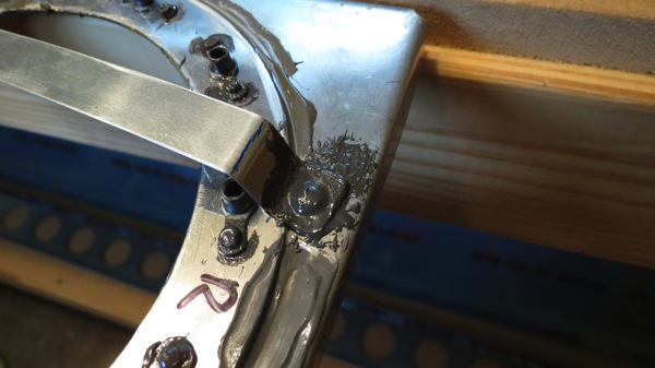
I did make one kind of dumb mistake with this though. The end of the shim (to the left in the photo) got distorted as I was squeezing the rivet. For the two -4 rivets in the hinge, the correct orientation was with the manufactured head against the rib (thinner material). But then I got on autopilot and did the same orientation for the last one, which was wrong – in that case, the shim is the thinner material. Sure enough, it distorted a bit when I squeezed the rivet. It looks ugly, but should be structurally sound – so I left it. The trapdoor itself doesn’t quite naturally sit flush against the rib, but in practice it’ll have the weight of fuel on it to help it seal a little better. And in any case, I doubt I’ll frequently be doing the kind of flying where this thing will be needed.

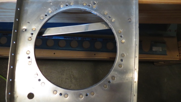
Next up were the anti-hangup guides for the flop tube. These presumably exist to keep the flop tube from getting hung up on stuff in the tank – the plans don’t explain much, they just show where to put them. The first guide goes across the access plate hole. The plans show this guide riveted to the plate reinforcement ring, but that would leave some space below and also block the access hole itself. So I decided to move it further back and make it longer, which necessitated having it rivet to the rib outside the trim ring.

Everything went well and I was feeling quite pleased with myself until I realized that the upper end of the guide was going to interfere with the cover reinforcement. Well, that’s a bit of a problem, especially since I’d already drilled the holes in the rib for the guide. I could relocate the top end further aft, but that would leave me with an open hole to plug – which isn’t really a huge deal – but more importantly, it would put the top end far enough back that the flop tube might get caught on the guide itself. Kind of counterproductive.

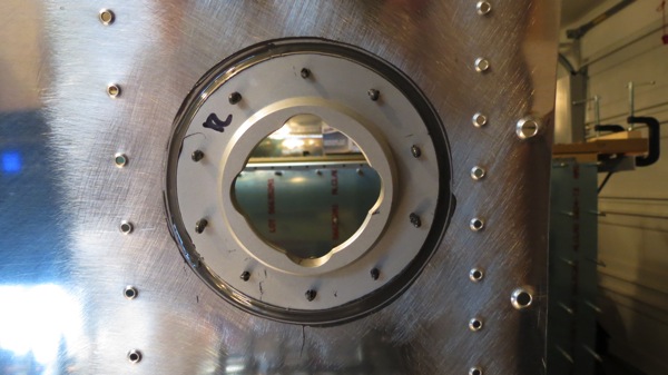
After thinking it over, I decided to notch the ring to fit around the guide. I don’t believe there’s an issue with material strength here – this area has three layers in total, the rib itself which is riveted to the reinforcement, and the cover plate which will be screwed into the nutplates on the ring. With a bit of trial and error, I had a good clearance notch:

IMG 2182

IMG 2183

I’m still going to run that little mod by the VAF gang as a sanity check. Worst case, I have to replace that ring, which isn’t a huge deal.

Next up I fabled the second guide, which runs at an angle between the second rib and the rearmost stiffener. This was easier since I didn’t have other stuff to get in the way, but kind of odd since the guide has a twist in it. Nothing really to it though. Finally, I put the inboard rib in place and installed the flop tube to see how it interacted with the guides.

Normal resting position (where this thing will probably spend 99% of its life):

IMG 2185

Up at the top of the tank. Notice that the end of the tube is pretty close to the guide. This is why I didn’t want to move it further aft; the end of the tube might actually tend to get caught between the guide and the access plate in that case:

IMG 2186

And the tube swung out to outboard:

IMG 2187

That made the inboard rib almost complete; the only thing remaining was to make the hole for the fuel sender connector. Five minutes with the unibit and that was done. Then I moved on to fitting the gas cap and drain flange. Nothing to really see here that wasn’t shown in the left tank, but I did actually cleco the drain flange from the inside this time to show how it will look, and more importantly, to do a quick test fit with the drain fairings.

Drain flange. Hooray:

IMG 2188

Flange with fairing. Looks much better, and I’m sure the small children who will actually see this will be appreciative:

IMG 2189

That just left the fuel vent line; I rolled off a length of tubing, cut to rough length, flared the inboard end (after botching the first try), and slid the thing into place. Then I dropped in the inboard rib and put the two bends in that bay to match the tube up to the fitting. Looking good:

IMG 2190

That only left one more thing: drilling the spar screw holes to final size. I’d put this off because a while back, I read about someone having problems with these holes cracking when they were dimpled. H recommended drilling them to a larger size, which I considered, but ultimately rejected. Instead I just drilled them to the normal size, and I’ll take extra care to clean the inside of the holes before dimpling to help stave off any potential cracks. I also pulled the left tank off the stand to final drill those holes in its skin too.

So that’s it…that makes this Deburring Week. And maybe next weekend will see my first sealing session…time to get messy!

Posted in Fuel Tanks, Wings | Hours Logged: 5

Fuel senders and flop tube stuff

So remember how I had that idea that I could finish all the tank internals this weekend? Let’s all laugh out loud in unison…OK, it’s not that bad, but I did fail to consider how things were complicated by the flop tube in this tank. That means that I’m not just repeating work I already did once, and even better, there are some not-very-well-documented steps to be done.

I started the day by working on the fuel sender plates. This of course was something I’d done before, so it went pretty quick. Rather than go through the whole trial-and-error fitting of the outboard plate to ensure it had sufficient clearance from the stiffeners, I used the trimmed plate from the left tank as a template to go ahead and trim the right outboard plate. That wasn’t quite enough though, as on the first test-fit, the aft corner didn’t have sufficient clearance from the stiffener. No worry though…pull it off, remove some more material with the Dremel and cutting bit, deburr, test again…much better.

With the plate done and set aside, I moved on to working on the inboard rib in general. First I clecoed the access plate reinforcement ring in place and drilled/deburred all the nutplate rivet holes. Then it was time to deal with the reinforcement and attach angle on the nose of the rib.

This is where things start to get interesting; while the standard fuel pickup in the left tank went through the access plate, the flop tube goes in through that whole stack of material at the nose of the rib. So three pieces have to be drilled to 9/16” in assembly. But I don’t have a 9/16” bit, which meant I’d be using the unibit, which doesn’t have deep enough steps to cut the whole assembly. Thus, I had to drill each piece separately.

First, I laid out my hole location on the attach angle, trying to roughly center it between three of the rivet holes:

IMG 2170

Then I center punched and drilled a small #40 pilot hole:

IMG 2171

Now the whole assembly gets clecoed together and the pilot hole is enlarged to 1/4”, through all the pieces:

IMG 2172

This is where things get fun. Making the hole in the rib and reinforcement plate was easy, but the attach angle is too thick to cut in one go with the unibit, so I had to enlarge the hole from one side, then flip the pieces and do the same from the other side as well. Between that and the bit chattering a little, the surface inside that hole was kind of ugly:

IMG 2173

But how to smooth it? It was just slightly too small for one of the Dremel sanding drums to go in there. Finally, I came up with a field-expedient solution, a sort of ghetto flap wheel. I cut a strip of emery cloth, taped it to a 7/16” drill bit, and it fit nicely into the hole:

IMG 2174

A little time with that cleaned up the hole nicely. Finally, I got everything clecoed together again and put the fitting and flop tube in place:

IMG 2176

This led to some other questions in my mind, though. The norma fuel pickup has an anti-rotation bracket, which serves a dual purpose of preventing the pickup from threading off the bulkhead fitting and also preventing the bulkhead fitting itself from rotating and moving the fuel pickup off the bottom. The plans call for safety-wiring the flop tube to the bulkhead fitting, but there’s nothing to prevent the fitting itself from rotating in its hole. Granted, it’ll be torqued in place and hooped up with sealant, so maybe I’m overthinking it, but I figure I’ll run it by the VAF gang just to be sure.

With that done, I moved on to one of the tank modifications to go with the flop tube. The plans call for a little trapdoor to cover a hole in the first internal inboard rib; these holes allow fuel to flow between bays in the tanks, which works fine for level flight, but fancy stuff might cause fuel to move outboard, unporting the flop tube. So the trapdoor acts as a check valve to prevent this from happening.

This is a part made from scratch, but it’s pretty simple: a square of 0.020” sheet, plus a little section of piano hinge. The end of the hinge is cut at an angle to provide a stop for the trapdoor itself. This was pretty straightforward stuff, though it did require me to make some executive decisions. For example, the plans show where to put rivets between the door and the hinge half, but don’t specify what type of rivets. But since the idea is for the trapdoor to sit flush agains the rib, it seemed that flush rivets were the order of the day. So I drilled #40 rivet holes, dimpled the door, countersunk the hinge, and put it together with 426-3 rivets.

Here’s the completed trapdoor assembly, from the backside:

IMG 2177

And sitting roughly in place on the rib:

IMG 2179

I didn’t drill/rivet the thing to the rib yet because, as the photo shows, the top hinge half goes across that stiffening channel, but there’s not enough material to put a rivet in the top right corner. I can put two rivets in the other part of the hinge half, but the plans call for three.So I’m not really sure what to do here…yet another question for the VAF brain trust, I guess. I suppose I could possibly cut another strip of 0.020 sheet and make a sort of bridge piece.

We’ll see…tomorrow…

Posted in Fuel Tanks, Wings | Hours Logged: 5

Match drilled right tank

So now work begins on the internals of the right tank. Tonight, since the tank was already together (aside from the end ribs and baffle), it seemed like a good time to get everything match drilled. If nothing else, getting the rivet holes out to full size makes it far, far easier to get clecos in and out, which will come in handy as I work on the fuel sender plates and so forth. So on went the end ribs and baffles, out came the reamer, and blah blah blah. After getting all the holes between the skin, ribs, and baffle done, I clecoed the stiffeners in place and match drilled those. Seemed like a good night’s work, so I knocked off for the evening there.

I’m hoping that over this weekend, I can complete all the bits and pieces for the right tank. This tank will be slightly more complicated than the left, thanks to the flop tube. There are a couple of extra bits that go in the inboard bay to ensure the flop tube can move freely and won’t get hung up anywhere. More on that once I actually get to working on things…

In other news, I placed an order with JDAir on Wednesday for some goodies, which came in today. The silver pieces on the right are fairings for the tank drains, and the blue pieces will serve as the ends of the fuel tank vent lines:

IMG 2168

Here are tank drains with and without a fairing:

IMG 2169

The fairings aren’t strictly necessary, but I think they look better than just having the drains sticking out, and I suppose they might reduce drag a bit, though probably not enough that I’d ever notice the difference. The vents just look cleaner than the stock option, which is just raw tubing sticking out of the bottom of the fuse. I’ll probably end up straying from the plans on the vent line routing as well. The plans call for the vent line to enter the cockpit, where they route up near the top of the cockpit rails (the idea being to have their highest point above the top of the tanks) and then out the bottom of the fuse. But a number of builders have been taking a play from the Harmon Rocket book and simply coiling the vent tube where it exits the tank, and having it vent directly out the bottom of the wing (example). Only caveat seems to be that the -8 wings don’t have as much extra room as the RV-4-based Rocket, but it sounds like the lines can simply exit through the gap fairing instead of the wing skin itself.

Anyway, I’m getting way ahead of my self now. More tomorrow…

Posted in Fuel Tanks, Wings | Hours Logged: 1.5

Right tank fitting

Ran out while dinner was getting ready and bolted all the attach angles to the right spar. After dinner, it was time to get to work for real.

First step was clecoing the tank together. As I mentioned before with the left one, this is quite a task, since the skin is really thick. It took me a solid 45 minutes to get all the clecoing done! After that, I moved the tank over to the spar, set it in place, and moved it over against the leading edge skin. At some point during this procedure, I took a look at the left wing and realized that there’s a slight gap between that tank and the leading edge. Nothing serious, just a tiny bit, but enough to annoy me. So I took extra pains to get the right tank aligned better.

The annoying gap:

IMG 2143

As before, after getting the tank aligned, I used a couple ratchet straps to hold it in place, but I also took the extra step of putting clecos through the screw holes at the spar. These holes are undersize right now, but they’re a good fit for the copper (1/8”) cloches, which also clamp nicely into the nutplates on the spar. Between the clecos and ratchet straps, I figured it’d be nearly impossible for the tank to slide out of position.

Instead of drilling the attach angles first, I started off with the screw holes to the joint plate, clecoing each hole after drilling it. Yet another tactic to help hold the tank in place. Then it was over to the inboard end to drill the five holes in that angle. Before removing the leading edge to get to the outboard angle, I had to get a “HEY LOOK AT MY WINGS” photo:

IMG 2141

Not too long after, the outboard angle was drilled:

IMG 2142

Then off came the ratchet straps and the tank skin, and I got the other five angles drilled through the baffle. Off came the baffle, and all the angle holes look great:

IMG 2144

I guess from here it’s on to doing all the fun tank detail stuff…I’m not going to be able to put off breaking out the tank sealant for much longer…

Posted in Fuel Tanks, Wings | Hours Logged: 2

Right tank attach angle nutplates

Lots of stuff to do around the house tonight, but I did find time to go out and rivet the nutplates onto all the tank attach angles I primed last night. Every little bit of work helps…

Here are the angles laid out in their positions on the spar:

IMG 2136

Posted in Fuel Tanks, Wings | Hours Logged: .5

Right tank joint plate, tank attach angles

Another so-so weekend. Josie had to help out with some testing with her job Saturday, so I had visions of getting up early with her and putting in a long productive day in the garage. That was before I realized she’d be spending that entire time on a conference call. Her work area is right by the garage door, which I leave open while working to help cool the place. And my first task would be match drilling, which would provide a double noise whammy of the air drill and the compressor cycling, which would in turn probably have a negative effect on her call.

So I instead took care of a couple work things of my own, and also spent some time doing some long-delayed improvements to this blog. The main thing I wanted was to start tallying up the hours I’ve been logging. I’ve put this off for a long time because I frankly hate getting into the guts of WordPress. Fortunately, I found another RV guy who was using some custom WP plugins, so I grabbed one of his and made some modifications to get the behavior I wanted. So now on the sidebar, there’s a running total of hours spent overall, plus numbers by each category link. Looks like I’m in for about 360 so far, so based on the Van’s estimates of 1600 hours, I’m maybe 25% done with this thing. I’d better start getting more productive on weekends…

Anyway, I did get out in the garage for a bit Saturday evening to get the right leading edge match drilled. Straightforward stuff, nothing much to speak of. Then I got the inboard leading edge rib – the one that’s not drilled at all – fitted it in place, and drilled the holes that attach it to the spar. I then moved on to the tank joint plate. Having learned from my mistake on the left wing, I took a different approach here.

The instructions tell you to draw a line 1/2” from the edge and align this with the skin rivet holes, which supposedly will give you 11/16” protruding from the skin. Well, when I did this last time, I had more than 11/16” protruding, which I thought was normal given how the instructions were worded, and I was of course completely wrong. So this time, I disregarded that instructions and just put a line 11/16” from the protruding edge. Then, when I slid the plate into place, it was easy to get it to a point where the protruding amount was just right.

The fun after doing this is trying to get the rib aligned; about all you can do is measure the joint plate protrusion from the skin and then try to match this measurement to the rib. It’s tedious, and I was getting frustrated, and just generally not feeling like I was in a good state of mind, so I abandoned the task and went in for the night. Better that than to misdrill and botch some more parts.

Today I was in a better mood, and got that rib aligned and drilled properly pretty quickly. After checking the holes to make sure they were fine (they were), the next task was to drill the tiedown hole. When I checked the location of the prepunched hole, it seemed off a bit, so I used a needle file to move it a bit before drilling to full size. I’m to really sure I improved anything, and I suspect I may have made the situation worse. The end result was a hole that doesn’t quite line up with the tiedown bracket:

IMG 2134

But the tiedown ring still goes in OK, so I’m OK with how things ended up:

IMG 2132

I may file the edge of the hole around some more when I take the leading edge assembly off though; I’m concerned the tiedown threads might be cutting the skin there, and I don’t want any accumulating damage from that.

Next up were the tank attach angles. The inboard one was already drilled, but the other six still only had their center hole drilled. I went through each of those, match drilling using the prepunch spar holes, then marked each for its location. Next came the sacrificial nutplates I’ve been using as drill guides; with the nutplate attach holes drilled, I countersunk by hand for NAS rivets, then took the angles out to be cleaned and primed. Like the left angles, I masked the face that will mate with the tank, since it’ll be covered in sealant.

That’s all for today…now it’s time to cleco the right tank together and get that thing fitted!

Posted in Fuel Tanks, Wings | Hours Logged: 3.5

Match drilled right wing skins

So I stopped at Home Depot on the way home as planned and snagged a shiny new air hose. The good news is that I have a new hose. The semi-bad new is that they had only two lengths, 50’ and 100’. I got the 50’ hose, which is roughly twice the length I should ever need in this 20×20 garage. Which in turn means that I now have perpetual hose slack lying around. Might have to figure out some way to store this thing at some point…

Anyway, after dinner I headed out, grabbed the drill and #40 reamer, and went to town on the skin holes. About 90 minutes and several hand cramps later, all the holes were match drilled, and I removed and stored the lower skins. Then I pulled out the right leading edge parts, clecoed that whole assembly together, and set it in place on the spar. I was in the process of clecoing it to the spar when I ran across another clearance issue with the wing stand: the leading edge skin interfered with the upper outboard arm. The previous owner of the stands had cut a slot there previously, but it wasn’t deep enough to accept my skin.

IMG 2130

Nothing that couldn’t be fixed with the Dremel and a cutting bit though. I took some material off the other slot on that same arm just to make sure I had plenty of clearance over there. Then I really did cleco the leading edge in place for good:

IMG 2131

That’s it for the night. I think I’ll start tomorrow by match drilling the leading edge; that’ll free up some clecos for use on the tank. Plus I might as well match drill now instead of waiting, since I’ve got the thing clecoed in place. I know from experience that it’ll come off and go back on several times, but once match drilling is done I can just use minimal clecos to hold it in place.

Posted in Wings | Hours Logged: 2

Right wing walk doubler

OK, so not much done tonight. After eating dinner and chilling for a bit, I was about ready to head out and get to match drilling, when I remembered something: I’d meant to stop at Home Depot on the way home from work, to pick up a second air hose. All I have right now is one of those little curly jobs, which has been a bit of a stretch to get just to the other side of the left wing. It might reach all the way to the far side of the garage (i.e. the top of the right wing), but it’d probably be really tight.

Oh well. At the least the hose should reach the bottom of the right wing, so I could at least match drill that and leave the top for later. I was just starting to get set to stretch the hose over when I decided to take a quick look at the directions – you know just for funnies. And I’m glad I did, because I completely forgot to make the wing walk doubler for this wing. That’s supposed to come before clecoing the skins into place. Whoops.

To follow the instructions to the letter, I’d have to completely remove the inboard top skin, since it’s supposed to be used as a drill guide for the doubler. Well, that would be kind of a pain, so I figured out a better way. The wing walk doublers are exactly identical, so I just pulled the left doubler and used it as a template for the right one.

(Come to think of it, if I’d been smart I would have just made both doublers at the same time previously. But that’s if I’d been smart…)

Tracing the cut lines using the left doubler:

IMG 2128

Drilling the holes using the left doubler as a guide:

IMG 2129

Then it was just a matter of deburring the holes, putting the left doubler back in place, and sliding the right one in place as well. I decided to just call it a night instead of trying to work out the air hose issue. Now I just have to decide what hose to get. I had a nice spring-loaded wall mount reel back in Atlanta, and it was nice, but I don’t have a good place to mount such a thing here without making big holes in the walls, and since we rent…yeah, that’s a no go. I should probably just get a regular straight hose instead of another curly thing, but then I have to worry about rolling the thing up between uses. Harumph.

Posted in Wings | Hours Logged: 1

Match drilled left leading edge, clecoed right wing skins

So my main objective for tonight was to get the skins clecoed onto the right wing skeleton. But first I had to address some other concerns; namely the very real possibility of not having enough silver clecos. I’d done a sort of quick and rough estimate Sunday night, and it was looking like my supply would be marginal to get the right skins on. So my plan was to remove some of the clecos I had holding the leading edge together.
I couldn’t recall if I’d match drilled the left leading edge yet, but I was pretty sure I hadn’t, and I turned out to be correct. So I decided to go ahead and match drill it while it was thoroughly clecoed, then remove about half or so of the clecos. With match drilling complete, the only real purpose of the clecos would be to keep the assembly together in a minimal fashion.
But first I wanted to take a look at the leading edge rib flanges that attached to the spar. Last time I put the leading edge in place, it seemed like I had to pull a bit to get everything lined up, so I suspected that some of those flanges weren’t quite square. A quick check confirmed my suspicion, and a bit of work with the hand seamers fixed that problem. This time, the leading edge went on the spar and it lined up without any trouble. Match drilling went pretty quickly from there; the skin-to-rib holes were stupid easy, though the rib-to-spar holes required me to use a long drill bit instead of my usual reamer due to tight clearances.
Hey look, the left wing is back together again:
IMG 2124
So I slid on over to the right wing and got to work clecoing. I’m pretty sure I said this when I did the left wing, but there are a lot of clecos here. I would estimate I spent a solid hour just on this task. I did the top skins first, then moved on to the bottom, working from inboard to outboard. I was down to the last few clecos when I noticed something wasn’t right. Oh, I see, the skin is interfering with the lower outboard arm of the wing stand.
Hrm, that’s a problem:
IMG 2125
So I proceeded to remove all the clecos outboard of the third rib, which allowed me to pull the skin out of the way. I also had to detach the outboard spar ends from the arms so I could pivot the wing out of the way. Only then was I able to get in with a hacksaw and start cutting a notch in the arm. Some cleanup with the Dremel, and all was well again:
IMG 2126
Of course, since I’d moved the wing around, I felt compelled to break out the plumb bobs again just to make sure I hadn’t introduced any twist into the wing while moving it. Everything checked out though, and now the wing is all set for match drilling…another night.
IMG 2127

Posted in Wings | Hours Logged: 2.5

Right wing on the stand

Finished setting up the right wing on the stand tonight. As with the left wing, there were some modifications that had to be made to the stands, but I’m pretty sure things went faster this time since I’ve done all this before. Now the skeleton is fully clamped in place, all sag and twist removed, and ready to accept the skins for match drilling.

After getting the stand all set up, I decided to go ahead and prime the tank attach countersinks, so I set about masking everything and shot the primer. Funny how the masking takes about six times longer than the actual priming…

No photos tonight, nothing really worth seeing.

Posted in Wings | Hours Logged: 2