Fuselage

Forward systems planning, again

Nothing too crazy tonight, just continuing with last night’s proceedings. I’d intended to start out by making a cardboard cutout for the upper shelf and starting with that. kind of like I did last night, but I decided instead to go straight to whiteboard drawing this time around. It has its detractions – most notably, I can’t use lay stuff down on a flat surface and visualize, I’ve gotta draw – but on the other hand, I didn’t have to start by cutting cardboard, and I could potentially adjust the shelf dimensions depending on what I found by trying to place stuff.

Probably the most notable thing I decided to roll with right off the bat was to try moving the CPI2 ECU from the lower shelf to the upper once. As mentioned last night, I wasn’t a huge fan of how crowded the lower shelf was. This may or may not be a decision that sticks – I’m going to make a VAF post when I’m done writing this to ask some questions about the CPI2 system, specifically opinions on how accessible the ECU should be. One of the nice things about this is that Ross Farnham, the owner of SDS, is very active on the forums and helpful. This is, in fact, one of the things that prompted me to go with the CPI2 ignition.

Anyway, the final thing that became evident tonight was that just the two shelves weren’t going to cut it for all the behind-the-panel stuff. This isn’t a huge deal, as I also have the backside of the baggage bulkhead I can use here, and that’s a pretty common place for -8 builders to put stuff. With this decision made, though, I think I have a pretty solid layout for this area – pending, of course, responses to the CPI2 questions, which might throw all this in disarray. But that’s the way things go.

First up is the revised lower shelf. Here, I just replaced the CPI2 ECU with the voltage regulators for the two alternators. I could probably put these a little closer together and gain some room with the fuse blocks, but that’ll be something to experiment with another time. This is, after all, still in a sort of rough-draft phase:

Next up is the upper shelf layout, which ends up being nice and roomy for everything. This shelf could actually be made wider, but I’ve intentionally drawn it so it’s narrow enough to pass through the space taken up by the main panel – if I ever needed to remove the shelf for maintenance or whatever, I could do it. Here I have the EMS unit on the left, the remote com radio center, and the CPI2 ECU and its backup battery on the right. I’ve also got what should be ample room to accommodate all the connectors here, particularly the large ones on the EMS (including a 37-pin D-sub):

And finally, a really rough look at the stuff on the baggage bulkhead. Here we have the Skyview network hub on the right, with the ARINC-429 interface box beside it. The ARINC-429 box is what will allow the Skyview system to talk to the Garmin GPS-175 certified GPS, and the location here is nice since the back of the GPS-175 tray will be close at hand (basically high and center). On the right side are the two backup batteries for the two Skyview EFIS screens:

I’m pretty sure that covers all the stuff that needs to live back here. I think at this point I probably need to review my electrical schematics and make sure I really have covered everything, and then…well, I guess it’s maybe time to see about fabricating shelves, These will be mostly simpler than the crazy aft shelf, but there will be the additional complication of the hinges for the lower shelf. Also, it’s possible my trashed wing skin may not be workable for these. Hopefully I’m wrong about that, since ordering sheet from Aircraft Spruce will make for some really expensive shipping…

Posted in Avionics, Electrical, Fuselage | Hours Logged: 1

Finishing the aileron trim system

Since I’m in a seemingly perpetual state of waiting for things for my primary work on the wings, I’m sort of reduced to finding smaller punch-list type items to work on. The aileron trim system has kind of been hanging over my head for a while. Some of the preliminary work was done a while ago; when I was working on the seat ribs, I got the necessary brackets riveted in place. But I got hung up on one part of the system, which is fabricating the pushrod.

Making this piece involves working with a length of aluminum tubing; drilling three 1/8” holes in one plane, then adding a slot 90° to that plane on one end to allow it to mate with the clevis on the trim motor. I made an attempt at this previously, but it didn’t go so well. I did a poor job of keeping all the holes in one plane, and eventually kind of put the thing aside in disgust. Well, tonight was the time to revisit this.

I don’t know if I’m just better at fabricating now or what, but I had no real trouble getting this done tonight. Don’t get me wrong, it was tedious at times, but not terrible. I drilled the three holes first, then went to work on the slot, which I started with a 1/8” hole, then started the slot with a couple band saw cuts, before spending a whole lot of time slowly widening it with a tiny file.

The resulting holes aren’t 100% perfectly in line, but they don’t really need to be. Overall, it looks pretty good, I think:

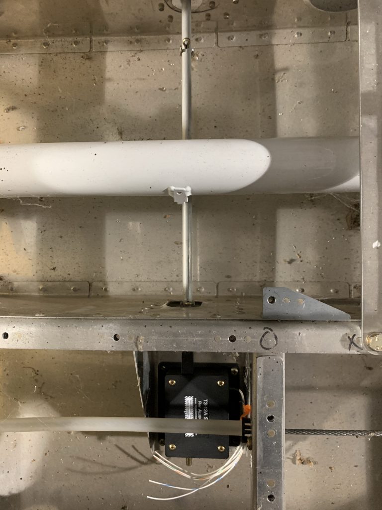
I’d intended to get the whole system temporarily installed in the fuselage for illustration purposes, but I only got as far as installing the servo and pushrod. One thing to notice here is that the two holes not used for connecting the pushrod to the servo now have cotter pins installed in them. This trim system works by spring bias; on each side of the control column, a spring will run from the cotter pin on that side to the small bracket seen on the column here. Actuating the servo just changes the balance point of the system.

I stopped at this point because getting those springs hooked up was not proving to be easy. I’m wondering if it’s permissible to trim the spring ends a bit to facilitate installation; right now both ends form a sort of full circle, so they have to be pried apart to hook onto anything. I dunno, and I don’t see any reason to figure it out right now. I’ll probably be flying initially without the springs in place, so as not to mask any rigging issues like a heavy wing.

But hey, here are things in the fuselage:

Now what next? You know, I think it might be time to pull the tail feathers off again. I still need to flip the fuselage back over and get the forward bottom skins riveted. That might also be a good time to pick locations for my antennas and get those mount holes drilled, even if I don’t permanently install the antennas yet. I guess that makes another thing I’ll need to go and order…

Posted in Fuselage | Hours Logged: 2

Fuselage teardown

Welp, this was one of those days where you kind of step backwards in order to move forward, or something similarly zen. I did get the conduit ordered from Amazon, and it did go out for delivery today, but via USPS, and they held it at the office, which means I won’t have it in my hands until Monday at the earliest. I may actually wait until Tuesday, as I also have my antennas coming – I ordered those from Delta Pop Aviation Thursday evening, and they’re already on their way.

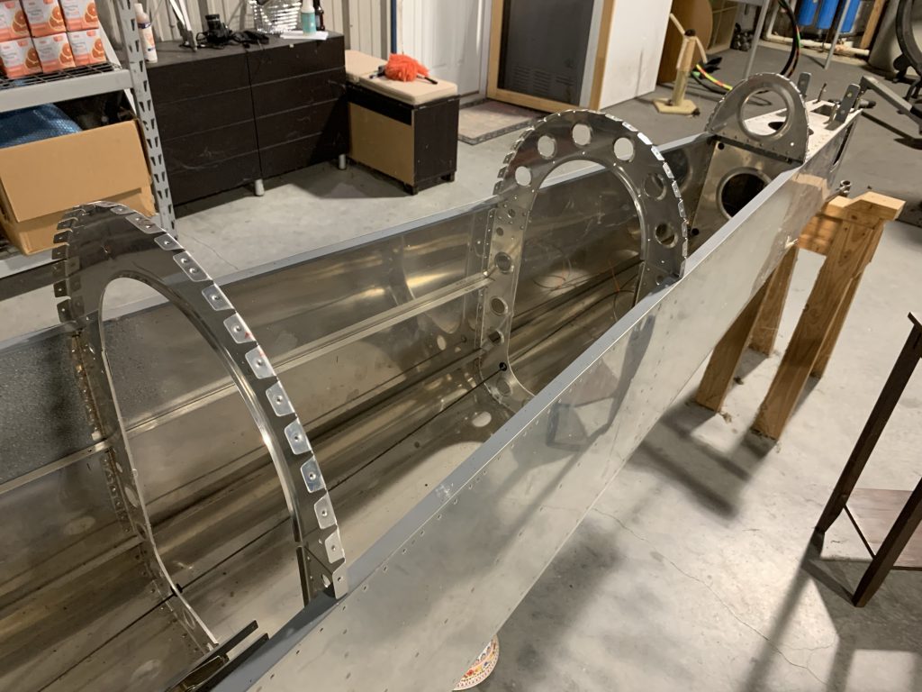
So with that in mind, I decided it was time to bite the bullet and get serious about the fuselage. Which meant removing most of the assorted stuff I’d put in there over the past several months. The tail feathers came off and went back into storage, the roll bar and panel came out, all my cardboard avionics mockups got put away, the control column and elevator pushrods got put by the wayside…and now it’s back to just looking like a canoe:

I also vacuumed out everything, which basically means I sucked up a whole ton of dead june bugs. Then I got the fuselage back into the rotisserie, and rolled on its side so I could look at the belly. Since the antennas are coming, I figure I’ll go ahead and get their mounting holes done once I have the templates in hand.

But first, I had to figure out where to put the antennas. There are four that I need to find homes for on the belly: two com radio antennas, and two blade antennas, one for the transponder and one for the ADS-B receiver. There are assorted placement requirements that kind of dictate where these will go. Specifically, the ADS-B receiver antenna needs to be at least 2’ from the transponder antenna, and the transponder antenna wants to be at least 3’ from any com antenna.

The com antennas should optimally be separated by 6’, but that’s simply impossible on an RV-8. Most small aircraft handle this by putting one on the belly and one up top, but there’s nowhere up top to do this. So the accepted thing for about every RV-8 I’ve seen is to put the com antennas just behind the main spar carry through, each one as far outboard as possible.

That means the other two get to go further back, and this is a segue into another consideration for placement: I want to be able to access these antennas relatively easily from inside the aircraft. That is, I don’t want them to live under any panel that’s riveted in place. The com antennas satisfy this, since they’ll be under the removable forward seat floor/footwell area. Further back, I have the rear seat floors and the forward baggage floor to consider; both of these will be riveted in.

This leaves two usable regions: the first is basically under and ahead of the rear seat, around where the rear stick is located. The other is aft of the baggage floor. Given the separation requirements, the most sensible thing seems to be to put one antenna in each region, and since the most confining requirement is the separation between the transponder and com antennas, that pretty much says that the transponder is going in the aft location.

So with all that in mind, I made rough marks on the belly as to the location of each antenna. These will of course need to be refined before I can actually drill holes; I need to figure out how far outboard the com antennas can go, make sure they won’t interfere with the aileron push tubes, and similarly check for interference for the blade antennas. But this setup gives me a little over two feet between the two com antennas, a little under two feet between the com antennas and the ADS-B, a good 3.5’ between the ADS-B and transponder, and over five feet between the coms and the transponder.

Works for me.


So that’s it for today. I still need to put away a lot of the stuff I removed today, and then maybe I should review the riveting instructions for the forward bottom skin – that’s been deferred for way too long.

Posted in Fuselage | Hours Logged: 3.5

Fuselage bulkheads

So I find myself working with a new sort of challenge when it comes to productivity on this project: namely, the fact that there ought to be plenty of things to work on right now, but I keep having trouble actually doing stuff. I’m fixating on the tasks that I really want to be doing – for example, the pitot heat plumbing that I’ve been trying to get the right conduit for. Granted, the August heat here in Houston also isn’t especially motivating, but still…

Anyway, as of yesterday my order from Van’s still hadn’t come in. Also included in that order was some 0.040 sheet stock, which I’ll be using to fabricate doublers for my antennas, and which I’ll want on hand before drilling the mount holes for those. That’s both the thing I’ve been trying to do put on hold. I was hoping the Van’s stuff would be at the post office today, but I wanted something to work on this morning.

What I settled on were the upper bulkheads in the tail, which will support the aft upper skin. I was originally going to leave these until I was ready for that skin, but while looking at running conduit back to the tail, I saw that the predrilled conduit holes go through the overlap between the lower and upper bulkheads. Ergo, if I wanted to get that conduit installed for running the wiring back there, I was going to need the bulkheads permanently installed first. And hey, the bulkheads aren’t the access problem, the skin is…might as well get going.

So I first spent about two hours deburring these things. Lots of nooks and crannies tom give attention to, lots of time with a needle file. This is often tedious, but today it felt good to be doing something (and I don’t just mean sweating). Next up were the harness fairleads – these reinforce the slots in the forward most bulkhead where the harness shoulder straps will pass through. These are thick aluminum stock and thus need some vixen file attention before going to the scotchbrite wheel. To be honest, I’m still not super satisfied with the smoothness, especially inside the slots. I think I’ll end up doing some more work on those with sandpaper or something.

Next, the fairleads were clecoed into place and the rivet holes match-drilled, then all the bulkheads got checked in place to the fuselage, and the rivet holes joining them to the lower bulkheads were match-drilled as well. The last thing I did before calling it a (sweaty) night was to add the gussets behind the forward bulkhead. Presumably these are to keep these from distorting, since they’ll potentially have a passenger leaning back against them. Only the bulkhead has prepunched holes for the gusset, and not the longeron – I guess I’ll get to drill those in assembly at some point. Interestingly, as I read forward in the instructions, it never actually says to do that, as far as I can see…

Anyway, here’s the fuselage with upper bulkheads in place:

Next up I get to add the canopy rail receptacle (at the top of the forward bulkhead) – this is what the aft end of the canopy will drop into when closed. Then I get to add the aft upper skin and other stuff and do a bunch of match drilling. At this point I’m thinking that I’ll get all the fitment tasks for the upper skin done, so I’m just short of riveting it, then I can put it aside until that time comes. Between that and other minor stuff, I should be able to keep busy until the end of the month, when I expect to – gasp – place my avionics order.

I got a quote from SteinAir this week, and I think it’s about time. All the mockup work I’ve done with cardboard cutouts of avionics boxes is all well and good, but I want the real things in place before I start actually making shelves and figuring out wire runs. I just can’t get comfortable with doing that stuff based only on cutouts, regardless of how correct they might be.

Posted in Fuselage | Hours Logged: 3

Just a bit more fuselage stuff

Today I was soundly beaten by the Houston heat. I got some work done in the morning before going across the runway for coffee, but after that I just wasn’t up for dealing with it.

During that single hour, I deburred the canopy receptacle and got it clecoed in place and match-drilled. Then I ended up doing some trimming on the gussets I put in place yesterday. They didn’t fit well against the bend radius of the bulkhead, and the wouldn’t sit flush, so I had to remove some material from the corners.

The next step would be to get the actual skin deburred and put in place, which can maybe be a task for tomorrow. A more pressing thing I’m thinking about is the two shoulder harness anchors. These are riveted to the top skin and the second bulkhead back from the rear seat, and are made out of thick alclad sheet. What’s interesting is that they need to sit flush against the skin, but also need to be relieved for the additional thickness of the bulkhead flanges.

By the plans, you’re supposed to file this area down to fit, but that seems like an unpleasant way to deal with this. First of all, this fitting has to be done with the skin in place, which means working inside the tailcone, which is already not fun. It’d be even less fun with the trial-and-error that comes with fitting work like this.

So I’m entertaining a different option – rather than filing the anchors down to allow for the bulkhead, why not instead make shims out of .032” sheet (same thickness as the bulkhead) to go between the anchors and the top skin? This seems like it’d achieve the same goal of ensuring the anchors sit flush, without the filing and trial-and-error. The only issue I can think of is that the additional material might make the joint a bit less strong in shear, which would be the expected loading if the harness was ever asked to do its job.

I’ve asked this question on the Van’s forums; it’ll be interesting to see what kind of responses I get. There are some good engineering types in there that ought to be able to point out any horrible flaws in this plane.

It also occurs to me that I could possibly do the filing of the anchors (per plans) without the repeated fitting if I use my .032” stock as a guide, which makes it a little less unpleasant. It still puts the onus on me to do some very precise removal of material, though.

Anyway, that’s it for today. It remains to be seen how much I get done this week, as it’s supposed to stay hot about all week. At least I’m still getting small things done from time to time…

Posted in Fuselage | Hours Logged: 1

Harness anchor prep

Not a lot to look at tonight – I just did the prep/modification work on the rear seat shoulder harness anchors. Last time I mentioned the idea of using shims between the anchors and the skin in lieu of filing a relief for the bulkhead flange, and…I decided not to do that. When considering the shim idea, I had a sort of vague thought that what I was considering might weaken the joint’s shear strength, but I couldn’t quite put it into words. As I figured might happen, someone on VAF set me straight.

Basically, simply adding the shim into the joint would result in it effectively “floating” between the anchor and the skin. Obviously this wouldn’t involve lots of movement, but in a case where the harness was put to the test, the shim could allow for a tiny bit of relative movement between the anchor and skin, thus allowing the rivet to stretch and/or bend a bit, instead of acting in pure shear.

There’s no telling how much this might compromise the joint – it might be tiny for all I know – but in the end, I don’t think it’s worth it to go off-plans here. So today after work, I got to filing. To make things easier, I clamped a 2×4 block in the vise and match-drilled a few holes using an anchor as a guide, which let me cleco the anchor in place while I worked on it. Next, a block of 1×4 scrap wood, clamped in place against the closest flecks, acted as a guide for the filing. All I had to do was keep the side of the file along the block as I worked, to get a fairly straight cut:

After a fair amount of trial and error, the relief was looking good. However, I didn’t want to leave the sharp edge left by the file and block, so I next went to the bench grinder and removed material to make the transition more of a bevel:

And finally, I did some fairly aggressive radiating of the long edges that will sit against the skin. The reasoning here is that these flat pieces will be attaching to a curved skin; I expect the radius should help these more easily fit snugly against the skin:

After this, it was time to go get the grass mowed, followed by dinner. I guess next up I get to cleco the skin in place and do a bunch of match-drilling…

Posted in Fuselage | Hours Logged: 1

Fitting the aft top skin

Boy, it’s been a while since I did a good old-fashioned cleco-match drill-uncleco work session. Kind of nice to do something so mindless, actually…

With the prep work on the harness anchors complete, tonight was just match-drilling the aft top skin to the bulkheads and other components. First, though, I had to knock a few years’ worth of collected dust and spiderwebs off the skin. If I’d followed the construction manual to the T, I’d have gone ahead and removed the blue vinyl and deburred the skin edges, but I figure I’ll leave the vinyl on until I’m about ready to put the skin on for good. For now, I just want to get to the point of riveting the upper bulkheads in place.

Anyway, with the skin cleaned off a bit, on it went. Getting it clecoed was a little interesting, particularly aligning the two center bulkheads, where I can’t just take one hand and move it into alignment. A straight pick was useful for inserting into one nearly-aligned hole, and then maneuvering the bulkhead so an adjacent cleco could go in. Then it was just a bunch of match-drilling.

Look ma, a turtledeck!

And then it all came back apart again… Look ma, no more turtledeck!

Next I get to do a bunch of deburring, plus figuring out what parts of the manual to do now vs. save for later when the skin goes on for good. I suppose the reasonable thing would be to just get deburring and dimpling done on the bulkheads and maybe the other parts that go in assembly. I’m thinking I can probably get these bulkheads riveted in place in my next work session.

Posted in Fuselage | Hours Logged: 1.5

Bulkheads!

Just a bunch of bulkhead work today. I’m kind of wishing I’d gotten a head start on this one of the previous two nights, but oh well. Originally I was thinking I’d be able to get these all riveted in place in the next work session, but I forgot one crucial step: the forward most bulkhead needs to be primed and painted before it can go in, since it will be visible in the interior. And before that can happen, some subassembly needs to be done.

I started off today picking up with deburring all the stuff I’d match-drilled previously, then moved on to the various dimpling and countersinking operations. Basically, I prepped every part except for the actual skin, which I’ll handle when it’s time for it to go on the airplane. There’s plenty of holes to mess with here, so this did take some time.

Next up was some assembly. The harness fairleads and canopy rail receptacle got riveted in place. The former was straightforward, as was the latter…kind of. An issue here are the three lower rivet holes, whose shop heads sit inside an acute angle. There’d definitely be no squeezing those with the tight clearance, and even bucking them with my skinny tungsten bar would have been a challenge. So I decided to use blind rivets on these instead. But then I was bothered by the idea of having some the rivets here be solid and the others blind (since the heads will be visible), and so I ended up just using blind rivets for all nine holes. Oh, and I had to drill out and replace two of them, because they didn’t quite go in perfectly flush.

It was late in the day by this point (I spent the middle of the day going out for pre-hurricane supplies), so priming today was out of the question. But hey, while I couldn’t rivet that one bulkhead, the other three could go. So I took those over to the fuselage and got them riveted. I was a little concerned about this, since some of the rivets joining the upper and lower bulkheads sit kind of tight against the skin and/or longerons, but I got them all squeezed with no trouble. Oddly enough, the most problematic ones were on the aft most bulkhead, which rivets to the aft deck. The two outboard riveted there are super close to the longerons, and I tried about three different ways before I ended up shooting them with a long straight set.

So now I’m all – well, mostly, I guess – bulkheaded up:

Hopefully tomorrow the rain holds off and I can get the last bulkhead primed and painted. It’ll still be a bit before I can rivet it after that – I’ve found previous that this granite-texture paint can take some time to really harden, so I’ll want to let that part sit for probably a week before I abuse it by doing some riveting. Kind of thinking I might go ahead and install the static ports and the first part of the plumbing while I’m in a bulkhead-ey mood. Maybe finally get back to the wing wiring stuff too, now that I have my conduit.

Posted in Fuselage | Hours Logged: 3

Paint, static ports, and conduit too!

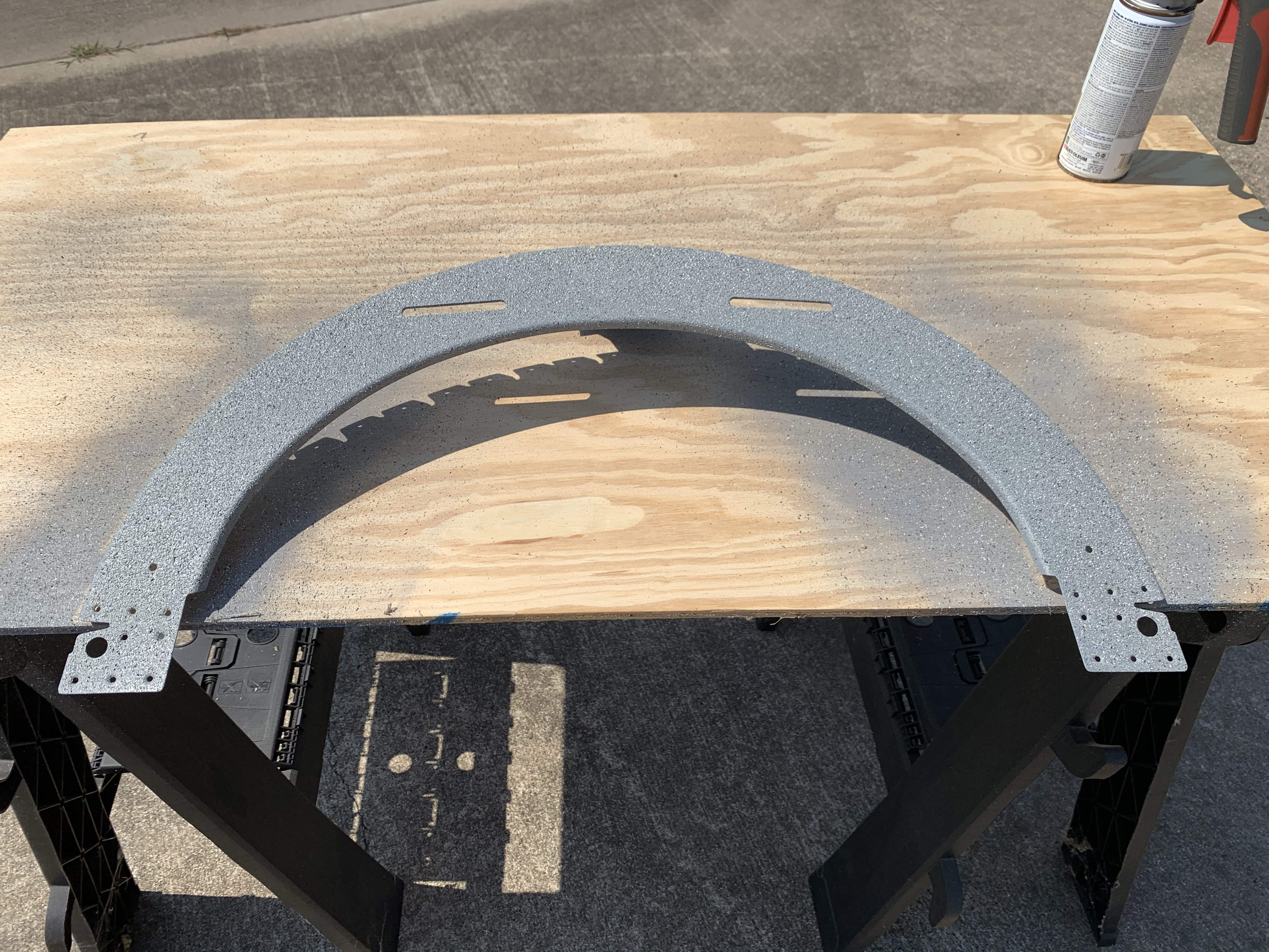
Nice productive day today, on a variety of stuff, even though I found myself needing things to complete some tasks. First up was getting the remaining bulkhead cleaned and scuffed for priming, then left out to dry while I went across the runway for coffee and chit-chat. By the time I came home, it was good and dry, so I got it primed. An hour or so later, with the primer dry to the touch, I went ahead and shot the stone texture coat, which I then left to bake in the sun. Apparently the heat and sun really help this stuff cure – previously I’ve found this paint to still be smearable a day later, but this time it was dry to the touch by mid-afternoon. It was actually dry enough that I went ahead and clecoed it in place in the fuselage, though I’m still going to wait until probably next weekend before doing any riveting, just to be sure.

Hey look, paint!
So with nothing more to do on the bulkheads, I needed a new task, and I decided to get going on the static ports. This ended up being a prime example of how vulnerable I can be to “analysis paralysis.” Before doing anything, I went inside to just look at some static system install photos, and ended up reading a whole lot of discussions about issues with static ports.

To preface this conversation, the plans method for static ports is, in the great tradition of Van’s, dirt simple – you just remove the stem from a pop rivet and bond it into a hole, then stick a tube on the inside portion. This is a touch crude for me (and others), so some time ago I bought a kit from SafeAir1 that included machined static port inserts.

Thing is, some people have reported airspeed issues with the SafeAir1 ports. From further reading, I learned that the first kits sold placed the static ports flush with the fuselage skin, unlike the pop-rivet method, which would put the ports slightly proud of the skin. Fortunately, later kits remedied this and left the ports similarly proud, and this is the type of port insert I have. Of course, there were still people reporting airspeed issues with those ports as well. Some people went so far as to install the port inserts on the outside of the skin, but still other people opined that this might cause errors due to being too proud of the skin.

Long story short, I could have spent all day trying to figure out the exact right way to do static ports, but in the end I was able to just go and install the ones I had. It seems that if I end up having any issues, they can be addressed a few different ways, so in the end I just did the thing.

Van’s says to place the ports four inches below the longeron rivet row, and one inch forward of the adjacent bulkhead row. Since the flanges on these inserts are larger than the plans pop rivets, I moved the hole an additional quarter-inch forward, to ensure clearance with the bulkhead flanges. After measuring a few times for good measure, I drilled the 1/4” holes, one on each side of the tail.

then there was the question of how to mount these. Some people rivet them, one people bond them, some people who really like to combine belts and suspenders do both…I decided I was just going to bond them. If it’s good enough for my fresh-air scoop forward, it’s good enough for this. So I scuffed up the mating surface of the inserts, as well as the mating area inside the skins:
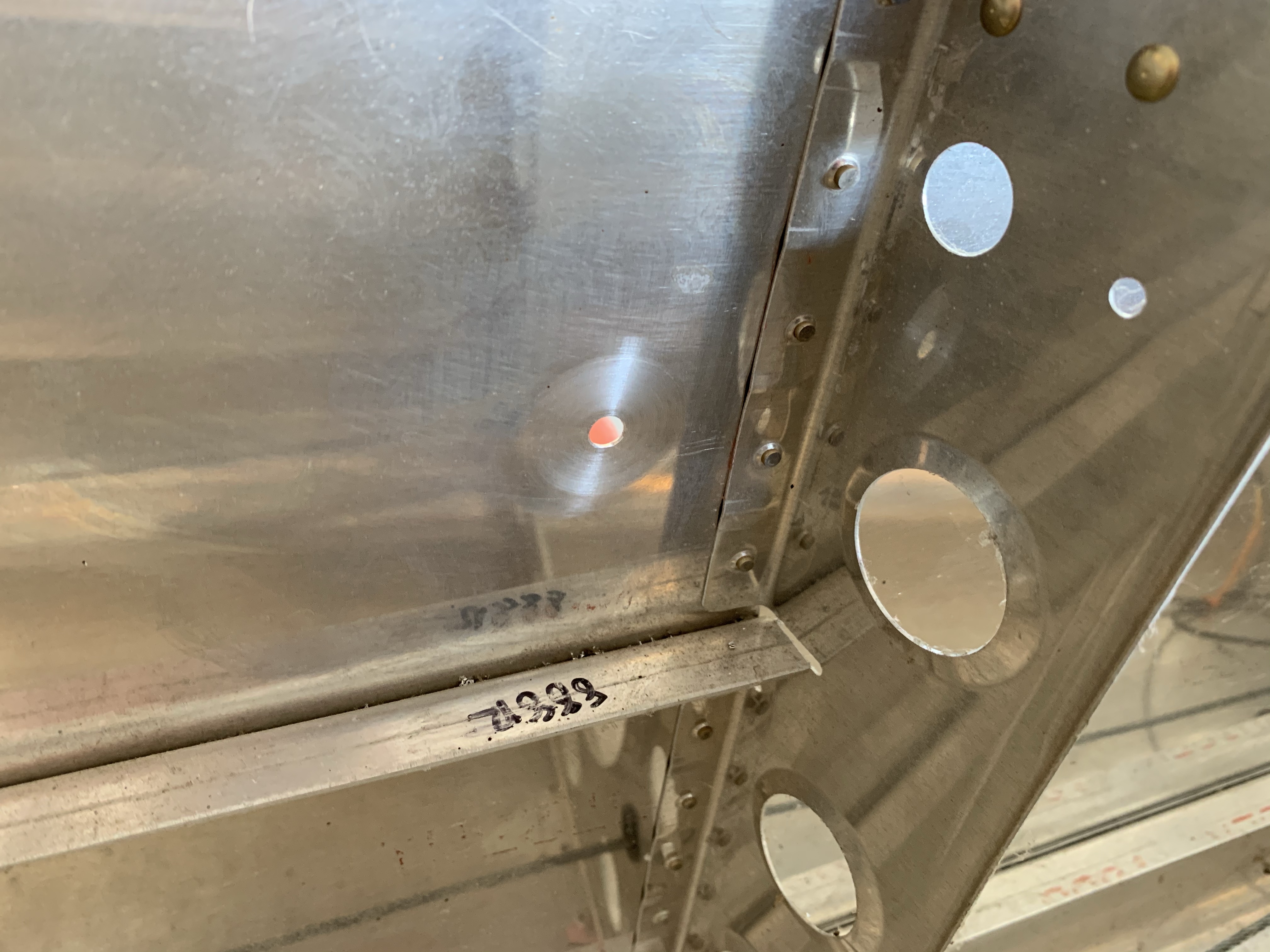
Here, though, I hot a roadblock: I don’t have any epoxy on hand. So much for bonding these today. I actually considered going out to buy some, but that seemed like an unproductive choice, especially since I’d probably have to go into Katy to find anything. Instead, tomorrow I can just run into Brookshire when the hardware store is open.

OK, so what next? I know, I can finally install the conduit that took me three tries to buy, and work on the pitot tube heat wiring. First up was locating the conduit holes; I reviewed the Van’s guidance on placement, which OKs a location between the forward most lightening hole and the adjacent one. I picked a center location that provided good distance between the rib edge, the lightening hole, and the stiffening ridge between the holes. I was initially going to make some sort of a jig so I could locate all the holes in the same place, but had a better idea, just using the intersection of an arc drawn off the hole, and a straight line off the rib edge.

With the holes located, I drilled pilot holes and then busted out the Unibit to open them up to 3/4”:
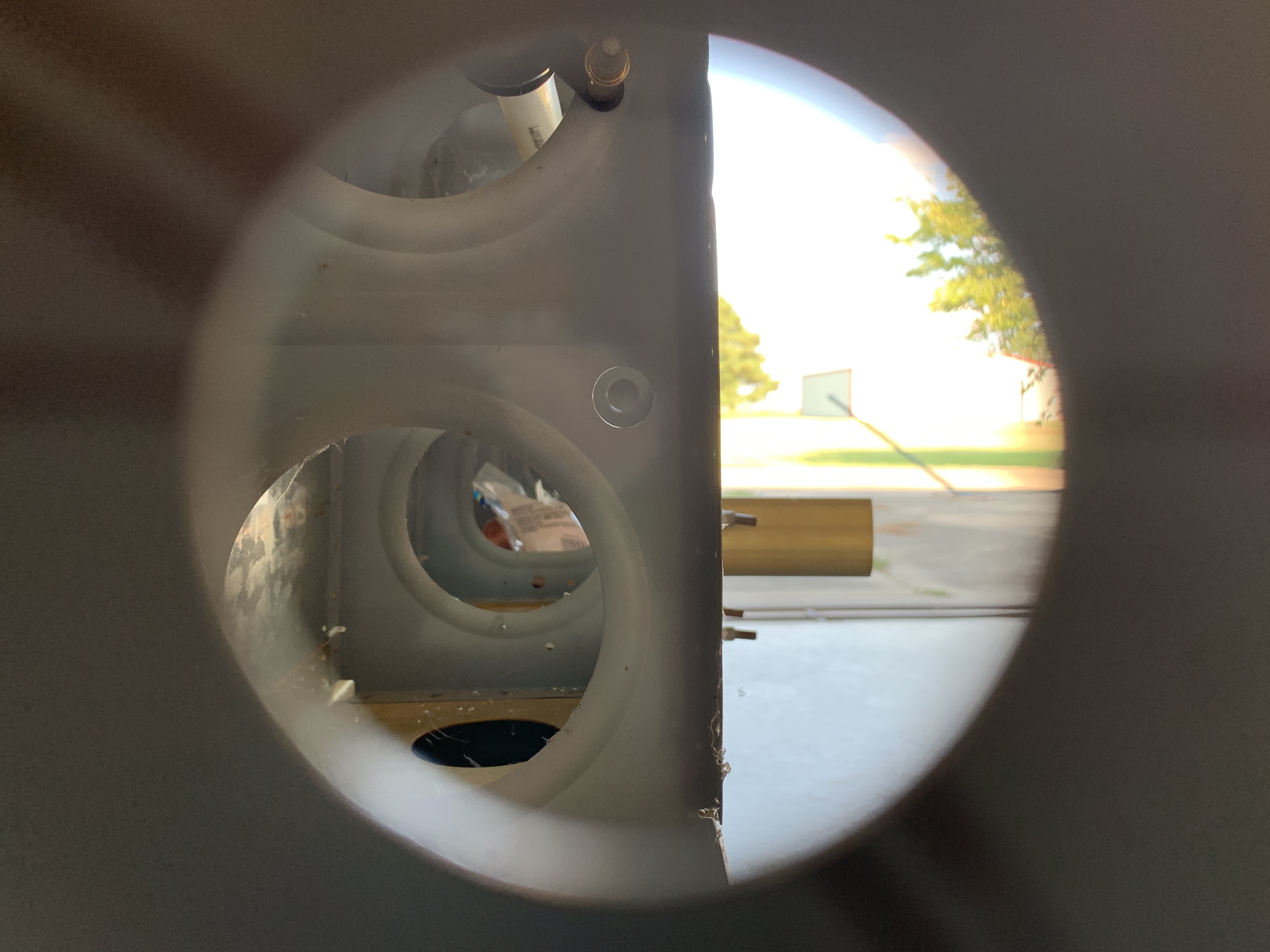
Then I measured the conduit run (about 24”), cut off some conduit with extra length for good measure, and pulled it through the holes. I see some people report having a lot of trouble doing this when they use this for wing wiring, but I found it pretty simple to pull through. The key is to stretch it was you pull, making the outside diameter shrink a bit so it goes through the hole more easily. I pulled the conduit relatively snug between the ribs so it wouldn’t sag, which should make running wires easier. Finally, I applied RTV around the conduit on each side of the rib penetration, to stabilize it in place and prevent vibration from cutting the conduit:
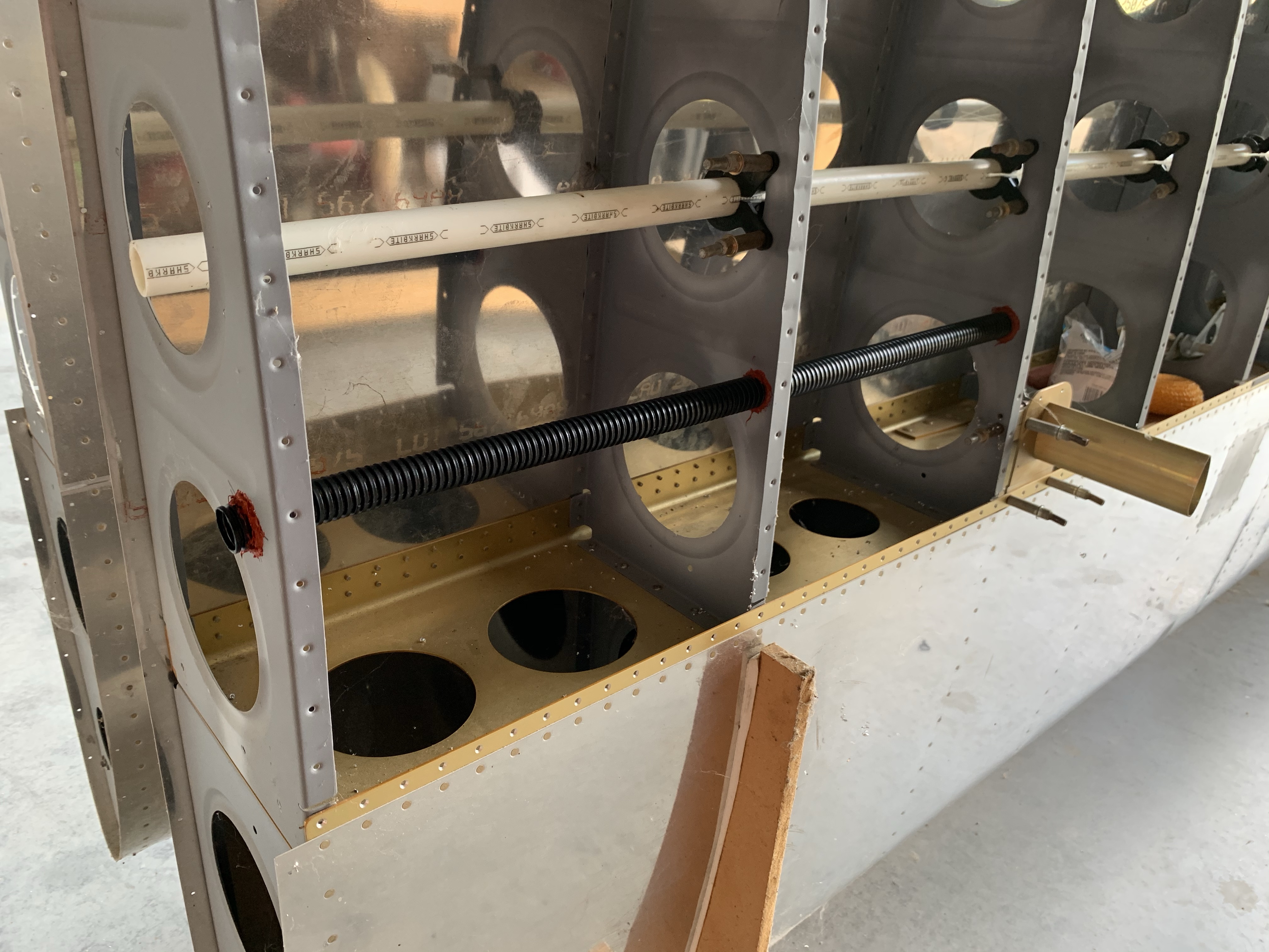
All right! Next I’ll locate the pitot controller and drill its mounting holes…wait, that’s a bad idea. I’ve got wet RTV down there, probably not a good plan to do drilling above that and embed aluminum chips in the RTV. OK, we’ll move on to wiring instead.

Since I’m extending the wiring between the controller and the tube, I’ll be adding an extra pair of terminals, which will need to pass cleanly through the conduit. This is particularly important, since my plan for dealing with the service loop of wire and pitot line will be to pull the slack out to the wingtip and secure it there (as opposed to letting it just sit loose in the wing bay).

Problem is, as supplied, the terminals both on the controller and tubs sit right beside each other, which would make for a very bulky spot in a snug conduit:
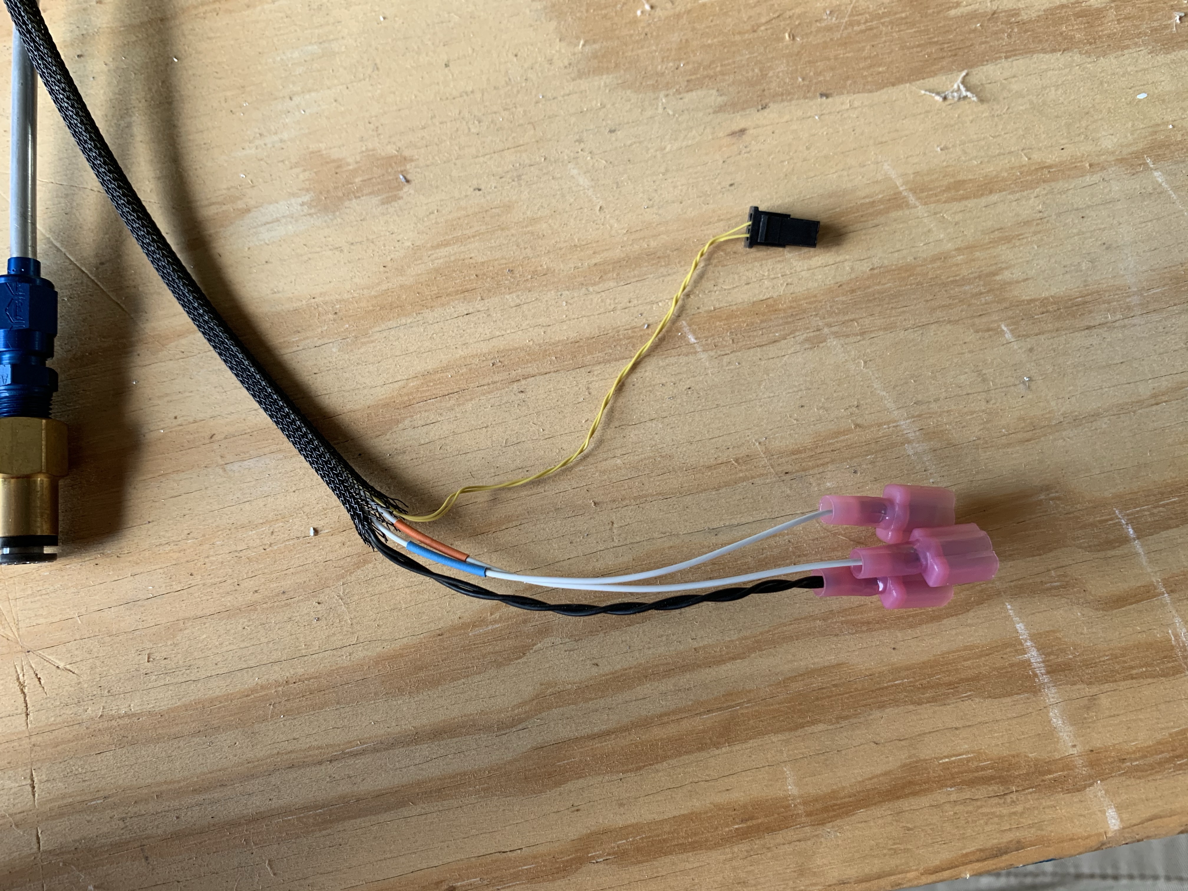
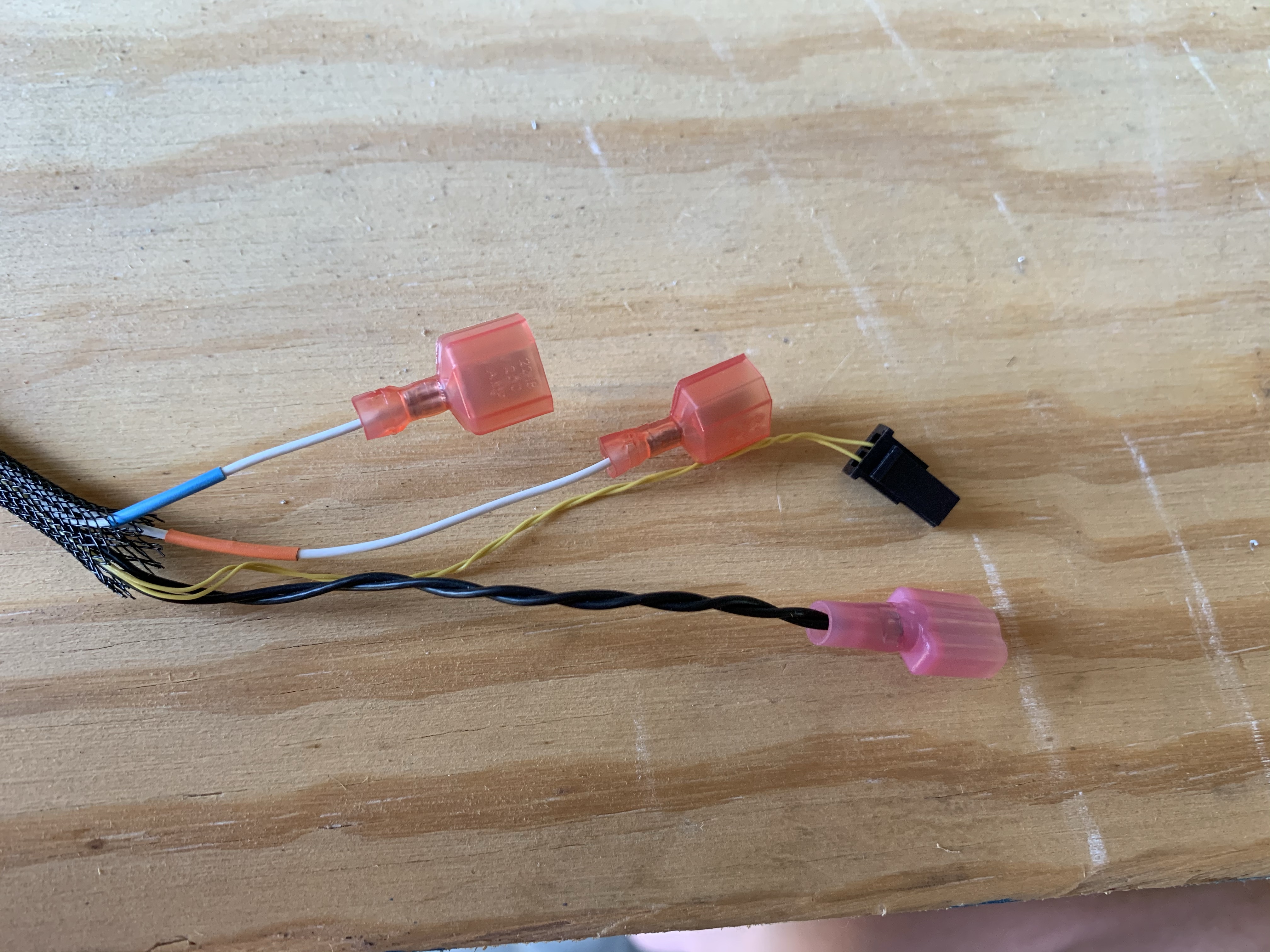
So I basically re-terminaled both the controller and pitot harnesses, staggering the wire lengths, which will allow the whole bundle to be slimmer. Once it’s assembled, I expect to wrap both joints in silicone tape or something just to help smooth them out even more. Here’s the same harness from above after trimming:
OK, now the RTV is pretty dry, so let’s get that controller located. To make this a little easier, I transferred the shape of the controller base into thin scrap plywood and thus made a template. I used the template to locate the first mounting hole, checked the actual controller in place with that hole, then used the controller itself as the template fo the other three holes. I considered going ahead and putting in the nutplates here, but for the moment I think it’s actually easier to use clecoes to temporarily mount the thing. Here it is with the two wiring runs roughed up: the feeds from the wing root coming out the white PEX conduit, and the harness going to the pitot tube going into the black ribbed conduit:
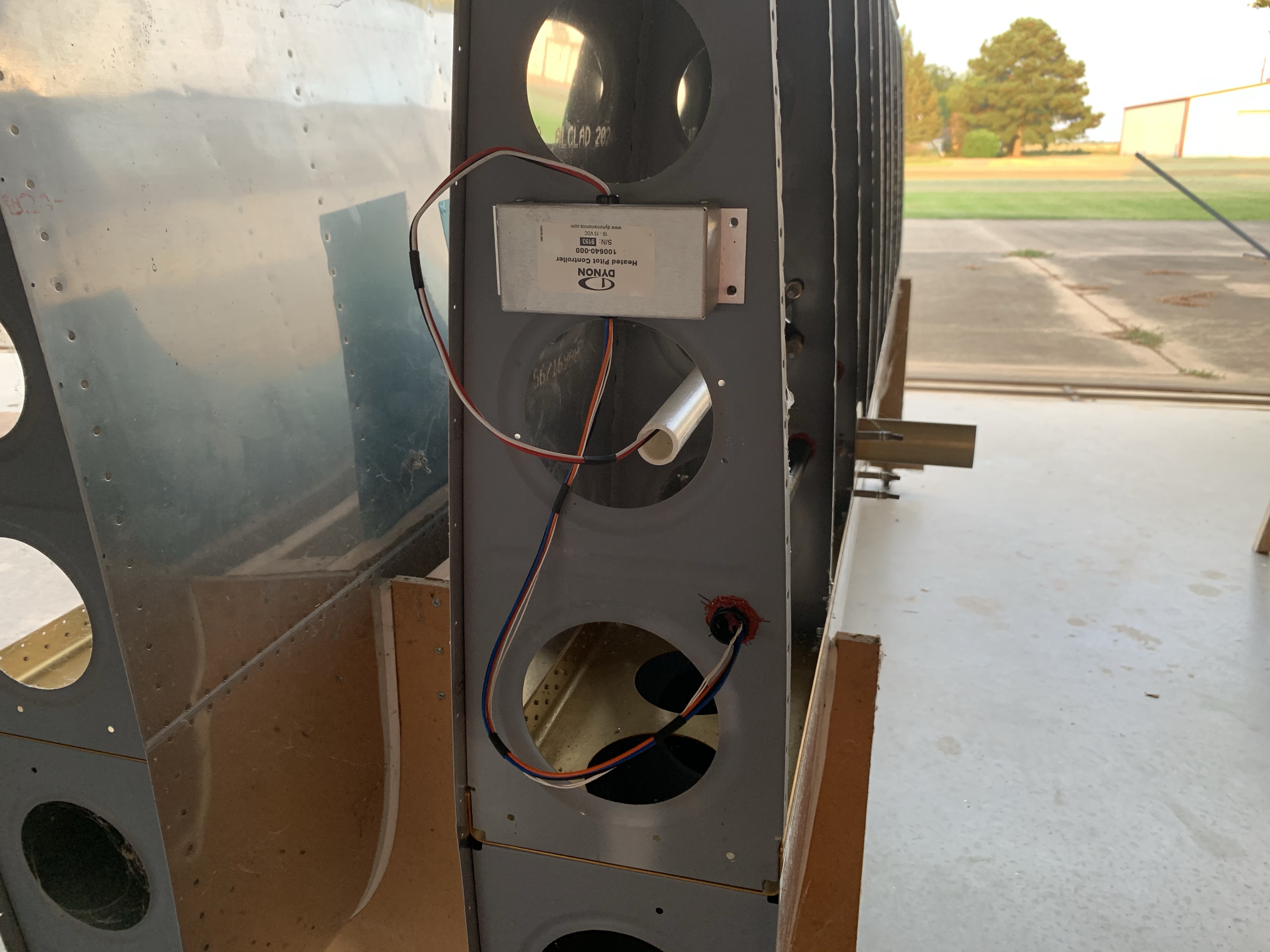
Finally, I had everything in place where I could make the extension harness that will go through the conduit! Well, actually not, it turns out. I only have red and black wire in the gauge needed for this run. Black isn’t an issue, since that’s the actual color of one run, but the other two are blue and orange. I’m not OCD enough to need the colors to actually match for those, but I do want to use an acceptable generic color, which is white. Red implies a power run – which these are, in a way, but I don’t like the ambiguity. I’d rather match the wires on the pitot tube harness, where there’s one black wire, and two white ones with heat shrink color-coded to match the controller wires.

So yeah, I need to order some wire to make this extension harness. And I guess colored heat shrink as well, but that I already found on Amazon, so that’s easy. Not sure where I want to order the wire from, I think I’ll be figuring that out tonight.

Hopefully tomorrow I can get those static port inserts bonded; if so, then I can go ahead and get the static line routing in place between the two ports. Just one more little thing.

I’ve also been thinking about my other conduit runs in the fuselage. I think I’m going to want two runs under the seat floors: the right side can house the wiring harness going to the aft avionics bay and tail, and the left one can route the pitot and AOA lines back to the ADAHRS. The other fun thing is the conduit I’d intended to run in the tail; if I run it through the holes I originally planned, it’ll exit into he baggage area, which I don’t want. Instead I think I’ll end up with a curved run, starting low in the bell crank area and ending up high at the tail. The challenge here is that the conduit run will go around a longeron, and I’ll need some way to keep that contact from wearing through the conduit over time. I’m not actually sure that this idea will work…another thing to think about…

Posted in Electrical, Fuselage, Wings | Hours Logged: 3.5

Static ports in

Super short today. I got myself some epoxy, and then this evening I bonded the static port inserts into place. I thought about starting on my antenna doublers, but decided to just make it a short night.

Static ports from inside:

And outside; here you can see how these ports protrude from the skin a bit, mimicking the profile of the Van’s pop rivet:

That’s it. Tomorrow I suppose I’ll work on the doublers, or else the plumbing to link these two ports together. That’s assuming I don’t feel I need to do some more hurricane prep, depending on what our friend in the Gulf does tomorrow…

Posted in Fuselage | Hours Logged: .5