Empennage

Elevator rigging – first pass

So…not a ton of detail to provide tonight, despite this being a solid two-hour work session. Basically, what I did was install the control column + sticks into the fuselage, and then rig up the pushrods all the way back to the elevators. Seems straightforward, but there was definitely some tedium to be found here. In general, it was annoying working leaning over the side of the fuselage (really makes me miss being able to roll the fuselage with the rotisserie), and in addition to that, there are some interesting limited access spots, oh, and it’s just dealing with things designed to move around.

In the end, while I got everything hooked up, there’s a lot of slop in the system, because I didn’t go to the trouble of installing all the proper spacer washers on rod ends, or of torquing down any of those connecting bolts – I just threaded them through and put a nut on to keep anything from falling out. Since the point of all this rigging is to get the pushrods adjusted properly, and to set up the elevator up/down stops, I think I need to do all this the right way…even though it’s going to be highly annoying.

I did reward myself after all this was done bye installing the forward seat floor and front seat, then throwing in a lawn chair cushion so I could climb in and make airplane noises:

And I figured a short video of the sticks moving the elevators was worth capturing:

Posted in Empennage, Fuselage | Hours Logged: 2

Elevator rigging refinement

Not a ton to report tonight, and no photos. My intent was to just have a short work session, mainly focused on getting all the rod ends installed correctly with spacing washers, and their bolts torqued down, to take the slop out of the system and get me setup for the upcoming work. Unfortunately this turned out to be easier said than done. The aft end at the elevator horns wasn’t too bad, despite access being a little hairy. The bell crank was actually fine as-is, and the connection for the aft pushrod there actually requires no washers.

The other end of the bellcrank, though, is where things got fun. This spot calls for a couple of thin washers to space out the rod end. Presumably this is to account for lateral movement – since that rod is connected to the control column, it’ll move side-to-side a bit with roll inputs. The problem is, this is the bottom of the bellcrank, it’s in a confined space between the two baggage ribs, and it was hard enough just to get the bolt threaded in there, never mind trying to do the frustrating-in-the-best-of-circumstances work of squeezing washers in. I gave it several tries, and even went so far as to lay down boards in the fuselage, climb in, and try working on my knees – all to no avail.

So I ducked inside for a quick VAF search. And there was a brief moment when I thought I’d found the solution. Someone recommended removing the rod end from the pushrod, installing it on the bellcrank out of the plane, then putting then bellcrank in place and finally threading the rod into it. Seemed like a genius plan, except…the bellcrank can’t be installed with that rod end in place. The extra width means it can’t be loaded in from above, and it’s not physically possible to weasel it in from below.

I came pretty close to admitting defeat at that point, but then decided to take a totally different tact – just gluing the two spacer washers inside the bellcrank. The only concern then would be that sliding the rod end in might knock them loose, so to help with that I bent the two bellcrank ears out just a hair – they’ll be pulled tight again when the pivot bolt is torqued.

So that’s sitting on the workbench letting the superglue cure (yes, I used superglue…), and we’ll see if tomorrow I can go back to making useful progress on this thing. Tonight wasn’t a lot of fun, but it was still educational. Also, I can’t begin to think of how obnoxious it’d be to install these pieces with the aft top skin on. Rather than leaning over the side, I’d have to be lying in the cabin with my head stuck into the tail…that’ll be fun one day…

Posted in Empennage, Fuselage | Hours Logged: 1

Elevator rigging wrap-up

No build activity yesterday, thank to some other stuff going on, but today I got a few hours. My idea of gluing the spacer washers inside the elevator bell crank worked out nicely, and I started off today by reinstalling the bellcrank and pushrods. With everything aft of the control column torqued down, the play in the system was all but gone, so the first step was to clamp the elevators in-trail and then adjust the large aft pushrod until the control sticks were vertical. I measured this by just sticking the magnetic smart level to the stick. It only took a couple turns of the forward rod end to get things nailed down.

That meant it was time to move on to the elevator stops. These are two pieces of aluminum at the tail, positioned so that the elevator control horns contact them at the extreme ends of their travel. Elevator travel is set up by trimming these pieces until both horns contact them at the desired limits.

The rear stop is pretty easy to get to – it’s a piece of angle that also bolts to the vertical stab. The forward one is a different matter – it’s a piece of flat stock that sits between the aft deck and a piece of angle on top of one of the bulkheads. Also there’s hardly any clearance in front of the horns to get to it. Basically, tweaking this piece was going to involve removing it, removing material, then reinstalling it…over and over and over. But I couldn’t even get a straight look at the thing with the vertical stab in place – so I ended up deciding to remove it. It’s beyond me why they have you install the vertical stab prior to trimming these things, there’s absolutely no need for it to be in place at this point.

Anyway, the elevator down travel (controlled by the forward stop) was already sitting within the allowable range (20-25°), so I figured I could probably get away with just removing the material necessary to get both horns to come into contact at the same time – remember that they’re not perfectly in line, the right on sits slightly aft of the left. I used drill bits as discount feeler gauges to figure about how much material needed to be removing, then got the stop out and went to work. It only needed about 1/16” off the one side to even things out:

And I only ended up needing to remove/reinstall it a couple times before everything contacted at once. Here’s a poor attempt to show this piece place. The horns  and center bearing are visible in the foreground, and to the left the stop piece can be seen peeking out from under the aft deck:

The rear stop was much more straightforward. As before, I figured out the rough amount of material to remove to account for misalignment of the horns, and did that work off the airplane with a cutting bit in the Dremel. The rest of the tweaking I did with the stop in place, filing away at each half of the stop. At first I made no effort to make things smooth, I just wanted to be removing material where the horns made contact:

Once the travel was correct and the horns were both making contact at the same time, it was time to remove the stop, make the transition between halves nice and smooth, and clean up all the rough edges:

And then it was time to final check the travel one more time. Acceptable ranges for up and down travel, respectively, are 20-25• and 25-20°. I ended up with just under 25 down and 26 up:

Then I reattached the vertical stab, mainly because it’s about the easiest way to have it stored in a safe place. Next step by the book is to do the rudder control stops, but I think I’m going to diverge from the plans here. The factory rudder stops are small angle pieces mounted outside the tail, which contact the rudder horn at the extremes of its travel. But there’s an aftermarket solution as well – a piece of delrin that attaches to a rudder hinge bracket, and limits the travel by contacting the spar. This will make the tail a little bit cleaner, and should also be less trouble to adjust. Problem is, I don’t have that part on hand yet, so I suppose I’ll order that tomorrow. In the meantime, I can move on to installing the flap motor.

Posted in Empennage, Fuselage | Hours Logged: 3

Rudder stop fitting

The holidays are over! Which normally isn’t something people say in a joyous tone, but in this case it means I can start getting back into the swing of things. I spent most of today working on building some new shelves for the hangar, but set aside some time in the evening to at least touch the airplane a bit.

In the time since my last post, my internal rudder stop piece came in, which gave me the chance to plan for its install. At a glance, it’s pretty simple – the stop piece has two AN3 bolt holes, and it just needs to be positioned on the rudder hinge bracket and matching holes for the bolts need to be drilled there. The catch is that simply using the stop – which is made of nylon – as a drill template could easily result in its holes getting enlarged. The instructions called for just marking and drilling holes, but I don’t really trust the accuracy of that method.

So I came up with an alternate plan: to fab up a drill bushing that would fit tightly in the bolt hole. This way, I could drill a smaller pilot hole using the stop as a template, then enlarge the holes to #12. I couple days ago, I took the stop with me to work, and stopped at Ace on the way home and went to scavenging. I was hoping for a small aluminum or steel spacer piece, but they didn’t have any small enough – the smallest were 1/4” OD, and I needed 3/16”. The tubing section, though, bore fruit, and I ended up buying a 12” piece of 3/16” OD stainless tubing.

Tonight, I took that piece of tubing and cut off exactly half an inch of it, then slowly ground down the bushing until it just slipped between the upper and lower hinge brackets. The stop can either be installed on top of the upper hinge, or between both hinges. I elected for the latter; it should be a bit sturdier, and it also positions the stop a bit closer to the control horns. I care about this because one of the criticisms of this piece is that if the pilot pushes hard on the pedals at the stops, it induces the spar to twist a bit. This is a problem that can be mostly solved by pilot skill, but mitigating it by reducing the distance between the two points of force application seems like a good belt & suspenders approach.

Anyway, with the bushing cut to length, I reamed it out to #30 (it was pretty close already), and then it was time to get going. Basically, the procedure was to clamp the stop on top of the upper bracket, drill one #30 pilot hole, then clamp the stop between the brackets and drill through the bushing and make the matching pilot hole in the lower bracket, Then the stop came out, those two holes were drilled out to #12, and then the stop was clamped on the upper bracket again, this time with a long bolt through the drilled hole to ensure position. Then the procedure was repeated with the other hole.

Here’s the stop clamped in place, ready to drill the first pilot hole. The bushing is visible on the left:

Then clamped on top again, with a bolt through the first hole:

And finally, positioned between the brackets, with both bolts in place:

I still need to figure out the proper washer stickup to put on the bolts between the brackets. The stop isn’t thick enough to fill the gap, hence the need for the washers. I have a pretty good idea, but to get it absolutely right, I’ll need to clamp a 1/2” spacer in the bracket hole for the rod end. I think I’ll probably have to relieve the stop itself for clearance around the rod end, since I chose to put it between the brackets. Hopefully I have a spare rod end around, otherwise I’ll have to remove the one from the rudder (not a huge deal really, but it means I potentially lose my careful length adjustment).

In other news, the past two weeks haven’t been wasted. I used the ample downtime away from home to put a lot of time into refining my electrical system plan and panel layout. I think I’m pretty close to a panel layout that I’m happy with, after soliciting and integrating some feedback from folks on VAF. I need to mock up my latest design in the plane and do some chair-flying to verify that I like the folks, but from just looking at it and thinking through procedures, I think it’s pretty solid.

Here’s the current working layout (click for a full-size image). This depicts both the panel itself and the right-side console, since the latter will be housing some things that I don’t think need to be in the prime main panel space:

Panel rev2 2 copy

About the only thing I’m not 100% on here is having the intercom on the right console. The faceplate fits fine, but the unit itself would stick out past the bottom of the console, unless I build a custom one (which I don’t really want to do). I’m not sure if I’m OK with that idea or not. I played with an alternative this morning a bit, and found that I can fit the intercom on the far right below the SDS CPI2 electronic ignition controller. Gotta think on that one a bit more.

Other than that, there are some small items that are still missing, but nothing major. I’m hoping to nail this down in the next month and maybe even (gasp) order some avionics…

Posted in Empennage | Hours Logged: 1.5

Rudder hanging

Time to get back at it. Tonight I decided to see about getting the rudder hung, preparatory to setting up the proper travel.

First oder of business, dating back to when I fitted the rudder stop a while ago, was relieving the center of the stop to allow for the rod-end hinge point to move freely, since I’m mounting the stop in between the hinge brackets. To get started, I removed the lower rod end from the rudder (and wrapped tape around the shaft to make sure the stop nut didn’t move and I could put it right back in the position I removed it).

At first I was thinking of making a cardboard template, tracing the rod end’s outline, and then using that against the stop, but then I realized there was a much simpler solution. I used a couple long bolts to put the stop in place on top of the upper bracket, and another long bolt to align the rod end with its pivot point. Then I just used a Sharpie to trace the outline of the rod end:

Then I just went to town on the stop with a sanding drum on the dremel. I was surprised how little material I had to remove. I saw someone else’s build log who’d done the same thing, and they’d marked off a pretty large area to remove. It only took a couple trial-and-error iterations to get the clearance I needed. Kind of hard to tell, but in this photo the rod end is sitting inside the stop’s pocket where it was above in the previous one:

Then I installed the stop in place between the brackets, including the necessary spacer washers (because the stop is thinner than the gap between the brackets). Then it was time to get the rudder hung!

This ended up being a bit more of an operation than I expected. Way back when I first did the empennage, I adjusted the rod ends for proper alignment when mounted to the vertical stab, so I expected to have the rudder just fit nicely, but…wrong. When I installed it the first time, I lined up the upper hinge, then the center one, and…the lower one was nowhere near being aligned with the brackets. Best I can figure is that as built, the stab spar had a bit of a bend in it, which was remedied when I fitted it to the fuse and ensured alignment.

Since I used a taut string to align the brackets, I figured I’d use the same approach to getting the rod ends aligned. But there was also the question…which of the three rod ends should I adjust? Upon inspection, the center one was clearly far further out than the others, so I decided to move it in. I also used the measurement from the spar to the rod end centers as a baseline for alignment.

This ended up requiring a couple of iterations as well to get right. The first attempt after checking with the string, the center rod end was actually too far in, so I got to remove the rudder again, thread it out a bit, and try again. Fortunately, that time everything lined up, and I got the bolts dropped in. So now I’ve got a rudder in place:

Next up will be setting the travel. At the moment, the stops clearly need a fair bit of material removed, there’s way too little travel. Before I can set this properly, though, I’ll have to work out a method for measuring the rudder angle. This was easy to do with the elevators, since a digital level could show angular displacement, but that won’t work for this. I suspect I’ll end up making a sort of manual protractor drawn on the floor, using a plumb bob on the rudder to track the travel. That’s for another night, though…

Posted in Empennage | Hours Logged: 1.5

Rudder stop adjustment

Tonight I picked up where I left off last night, with working out a method to measure rudder travel. As alluded to previously, I ended up creating an angle reference on the floor and using that, plus a plumb bob at the trailing edge of the rudder, to get things worked out.

I’d been sporadically giving this thought throughout the day, so by the time I finished dinner I had a pretty good idea how I’d proceed. The basic idea was to draw a centerline aligned with the fuselage, mark the rudder pivot point on that centerline, and then use good old trigonometry to lay out the necessary angle reference lines, which I could then compare to the plumb bob position.

This meant I needed to to some drawing on the floor, which in turn meant I needed a surface I could draw one. I also needed to be able to secure it in place, since if my reference thing moved, it’d kind of munge up the whole works. Paper seemed the material of choice, but I needed to cover an area roughly 2’x3’. I guess I could have taped together a bunch of printer paper, but that seemed annoying. After poking around the hangar a bit, I found the perfect thing. A while back when Josie and I were doing a fair bit of shooting together, I bought an enormous roll of full-size paper silhouette targets, and we’ve come nowhere near using the entire roll. One of those, turned facedown, was the perfect canvas.I folded the sheet in half to help me initially position the paper at or near the centerline – it’d be annoying if I taped the paper down and then it was way off-center and I couldn’t draw all my angle references.

Th initial centerline was laid out using the tailspring as the reference. The one complication here was that there was no good way to hang a plumb bob right on the center of the spring – so I ended up hanging it off each side at the forward and aft end, resulting in two pairs of marks. Finding the halfway point between each pair gave me my centerline reference. I meant to take a photo of this procedure, but by the time I remembered that, I’d already removed the bobs. Oh well.

Next, I needed to locate the rudder pivot point, which would be the vertex of all the angle lines I’d be drawing. To do this, I just removed the bottom hinge bolt, ran the plumb bob string through it, and got my mark made. This time I actually remembered to get a photo (note that I also had to remove the tailspring since it would have been right in the way here):
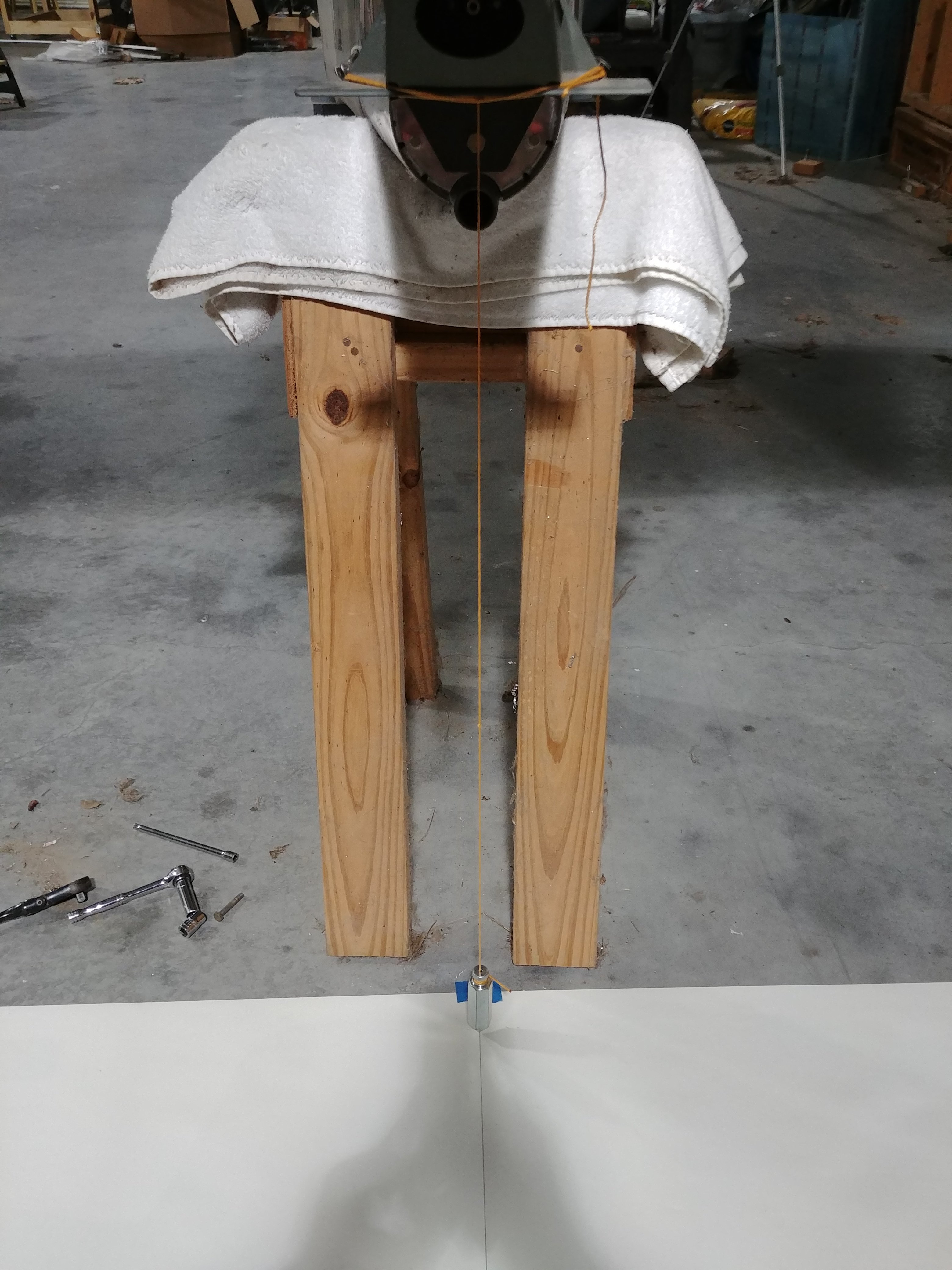
Now it was time to resort to math. The specs for rudder travel are between 30 and 35°, and for whatever reason I decided to draw a 25° line as well. The basic idea here was to identify, for each angle, a right triangle with measurements that were close enough to normal fractions to be measured pretty accurately with jut a yardstick. That was just kind of trial-and-error: get the tangent value on my phone calculator, and multiply it by successive whole numbers until the result (the other leg of the right triangle) was relatively tidy.

Next I laid out the centerline/“long-side” measurements along the centerline, and used a square to draw perpendicular reference lines at each point. Then I could use the yardstick at each point to measure the short sides of the triangles and mark those points. Finally, I used the yardstick to draw lines from the vertex under the hinge point to each of those points.

The result is a little difficult to make out since I just drew it with pencil, but I’ve got my nice reference lines:
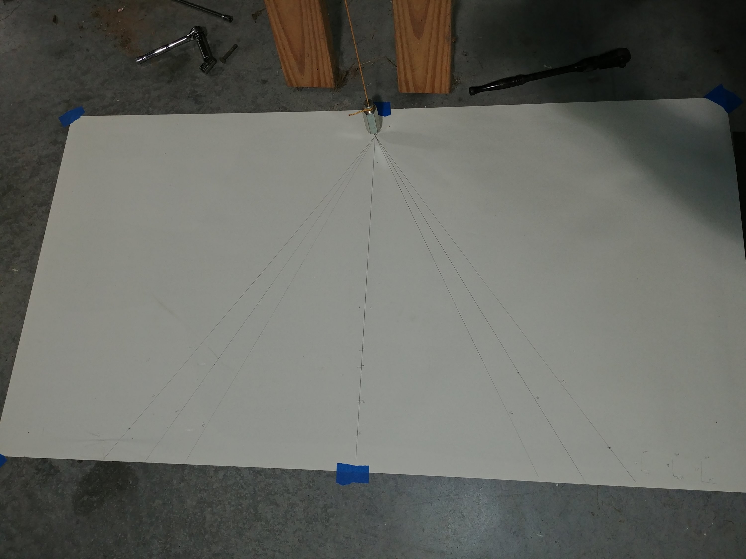
This was where the night got interesting. With the reference lines in place, I was able to get an idea of where my travel was to begin with, and it was way off – maybe 15° in either direction. I started filing away at one side of the rudder stop, but it was tedious work in a tight space, and I hardly seemed to be making any progress. It seemed that I was going to have to remove a substantial amount of material.

This was the point where my spider-sense started to go off a bit. Everything I’d read where people talked about installing this stop, they indicated it needed hardly any trimming at all – which was not how I’d describe the work I was about to start doing. Something here didn’t add up, and so I stopped to go do some digging.

What I finally realized was that I hadn’t set the pivots on the rudder up to spec. These are simple rod-end bearings, and they’re screwed into/out of large nutplates on the rudder spar to adjust the distance of the hinge point from the spar. When I messed with these last night, I got them all aligned so the rudder could be physically mounted, but paid no attention to any actual spacing specs. And there are very specific specs laid out in the plans, and I was pretty sure the bottom rod end was threaded in significantly more than it ought to be. This would explain why my starting travel was so small – with the rod end threaded in too far, the rudder spar was closer to the rudder stop than it should be, and thus made contact after very little travel.

The conclusion was inescapable: I needed to remove the rudder again and check those bearings. I might even have to take the thing on and off several times to get the bearings lined back up again. And I was worried something would move and all that work for my angle reference would be wasted. I actually almost quit for the evening, but that also made me worry that an errant dog might tear up my angle reference too. Eventually I decided to press on.

As seems to be the case with most tasks I dread, it was no trouble at all. Once the rudder was off, I checked the bearings – the top one was to spec, the middle was a bit wonky, and sure enough, the bottom one was in too far. But I figured that if I was strategic with my bearing adjustments, I could preserve the alignment of them all and avoid more trial-and-error. The bearings are equidistant apart, so if the upper one wasn’t moving, then all I had to do was make sure that the number of turns I put on the lower bearing was twice what I put on the center one.

Three full turns got the bottom bearing to spec, so I gave the center one 1.5, then went to give hanging it a try again. And it worked – everything lined up on the first try! And now my starting rudder travel was closer to 25° – much better.

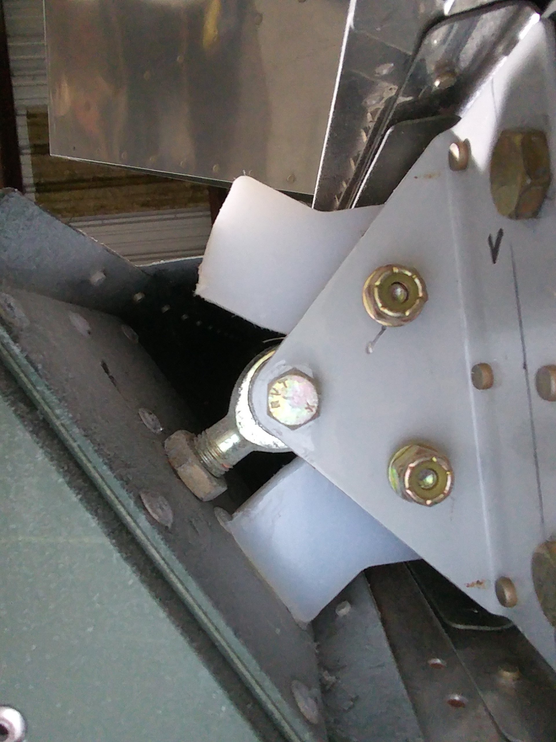
From there, it was just a bunch of progressive removal of material from each side of the stop. I chose to stop right at the 30° mark on either side. The other spec that must be met here is the clearance between the rudder and the inboard end of each elevator. I figure more clearance here is good – the idea here is preventing those two surfaces from ever coming in contact. RVs are pretty well-known for not lacing rudder authority, so I don’t see any reason to try and get closer to the max 35° travel spec.

And the rudder stop now makes nice, even contact with the spar at max deflection:
I think my next order of business will be securing the exit sleeves for the rudder cables, temporarily connecting the cables, and setting up the rudder pedals temporarily. Then I’ll be able to sit in the cockpit and make two control surfaces move! I think I could go ahead and get most of the brake system installed in the cockpit, but I’m not sure I want to do that right now. That seems more like a thing to do closer to final assembly.

If I don’t do that, then…well, I’m about as done with fuselage work as I can be right now. I do still have riveting to get done on the lower forward fuselage, so I suppose I’ll have to remove the tailfeathers once I tinker with the rudders so I can flip the canoe over again. Then I’ll have to find something else to do – probably closing out the wings and doing some fiberglass work.

I really need to get on my bank-robbery plan so I can start ordering some expensive stuff. It’s getting to the point where systems work isn’t something I can put off any longer. Which I guess means I need to sit in the cockpit and do some more chair-flying so I can finally decide that I’m happy with the panel layout.

Posted in Empennage | Hours Logged: 2.5

Rudder cable stuff

OK, so this wasn’t exactly the most victorious of work sessions. I’d hoped to get the rudder cables rigged up and the pedals set up properly, but I didn’t make it that far.

You see, before connecting the rudder cables tot he rudder, I needed to secure the little plastic tubes that protect the cables where they exit the sides of the fuselage. Seemed pretty simple – it’s just an adel clamp on each tube, screwed to the fuselage side. Except the manipulation required to get those things in place was made rather difficult due to lack of access to that area. The attach point is behind the first mostly-solid bulkhead, the one that has the horizontal stab attached to its top. It has two holes, the smaller of which might be able to accommodate a toddler’s arm, and the larger of which has the elevator push tube passing through it.

I got a little more working room in that larger holes by moving the elevators to full up – this displaces the tubs upward a bit – but even then I could barely get my wrist through there. Long story short, it took pretty much a solid 45 minutes to get those things in there.

This was followed by another 10 minutes trying to find the bolts needed to attach the cables to the rudder horn. I was about ready to knock it off then, but decided I might as well push through and attach the cables to the pedals, then anchor the cables to the firewall. Then I remembered that I need to have the idler arms for my rear-seat pedals in place for all this to work, so I decided to jut call it a night. Maybe next time.

Posted in Empennage | Hours Logged: 1

Rudder system rigging

Basically what the title says. Tonight I got the rudder pedals rigged up.

Last time, I quit for the night after realizing I needed the rear pedal hardware in place before messing around with the pedals. Here’s a look at what the attach between the aft rudder cables and the short ones attached to the pedals looks like. I put the bolts in here last time just so they’d have somewhere to live:

So I went poking around trying to figure out where I put the rear rudder pedal kit. That’s building in a nutshell, you can spend an amazing amount of time wandering around the shop looking confused. Anyway, once I got the kit and the proper hardware, I got the idler arms installed, and then the cables reattached. Basically, the only difference here is that the connection between the two cables also is in common with the top of an idler arm. The rear pedals are a couple plunger-type pieces that push on the tops of these idler arms.

Here’s the new/correct rigging up here:

With that done, the final step was to attach the forward ends of the cables to their anchor points on the firewall. The basic way the rudder cables function is that the cables pass through S-shaped passages on each pedal. When a pedal pivots, it “wraps” the cable with that S-shaped passage, thus pulling on that cable (or relaxing, depending on direction of movement. At the same time, if the pedals don’t pivot, they can slide forward or back (for adjustment) without pulling the cables. Kind of ingenious, really.

Anyway, at this point the resting position of the pedals are adjusted by moving around washers on the forward cable anchors. The shanks of these pieces are way longer than the holes they go through, and by changing the distribution fo washers between the forward and aft sides of the firewall, the resting position of a pedal can be changed. So the procedure is to clamp the rudder in a neutral position, and mess with the washers until the pedals are vertical. I ended up setting them up with a slight rearward angle, as otherwise they get really close to the firewall at full deflection. I can always tweak this down the road, of course.

With that done, I had a functional rudder system. Which I of course tested by climbing in and actuating the pedals. Which was cool, but I also noticed a sort of chafing noise, which concerned me. I got Josie to come out and look around while I work the pedals, but there seemed to be no single source of the chafing. Some research on VAF seems to indicate that it’s not unusual for the cables to make contact with the snap bushings that line bulkhead passthroughs, but I’m still unsure about the sound. Time to go make a post and ask.

The other thing I noticed while sitting i the cockpit is that the rudder pedal assembly isn’t as secure as I’d like. The forward-aft slide bar is bolted securely in place, but the nylon blocks at the left and right sides, which I thought were supposed to rest on the floor, don’t. Thus the pedal assembly can rock left and right a bit around the slide bar. There’s another thing to ask about…maybe I’ll need to add some spacers down there. On the other hand, if it fits tight against the floor, seems like that would make adjusting the pedals challenging, so I’m kind of unsure here.

But hey…rudders!

20200203 2220183387909137173031696


Posted in Empennage, Fuselage | Hours Logged: 1

Even more lower shelf, plus some more planning

Well, this is actually two nights’ worth of work – I neglected to bang anything out here for yesterday. The main thrust has been continuing to work on that lower shelf. Yesterday I fitted the hinge half to the shelf, laid out the rivet locations, and drilled them together. Tonight I got the shelf dimpled and the hinge countersunk, and riveted the two together. I also removed a few hinge eyelets in the middle of both halves – since space outboard of the hinge will be limited, there’ll be no way to ever pull a single-piece pin out to either side, and thus no way of ever removing this shelf for service once it’s riveted in. I don’t want that, so instead I cut the hinge pin into two halves, which can be removed by pulling either one from the center of the hinge assembly.

The shelf with the finished hinge setup can be seen here:

Note that the far side of the shelf isn’t final-cut yet; I’m going to mark that once I have the whole thing fit into place in the aircraft, and trim to that line, rather than measuring. This should get me a better fit, at the cost of a couple more fitting iterations.

The bigger news, though, is that today the UPS man brought me a sizable package from SteinAir, which contained the bulk of my avionics. Or maybe all of them, depending on how you define the term. I wasted no time in opening boxes and starting to use the actual avionics boxes to verify some of my layouts:

This turned out to be a good thing; it seems my previous upper avionics shelf plan has some issues. The biggest thing I didn’t account for is that I can’t use the entire front-to-back width of the shelf. There are two reasons for this: the first is that there’s about 1 1.5” overlap between the shelf and the forward upper brace, and I can’t put any attach nutplates there. There are also the items I was planning on putting inside the baggage bulkhead; the most notable things here will be the voltage regulators, which are just under 2” tall.

I have a few new ideas about how to resolve this, but I think before I can really commit to any of them, I’m going to need the final missing component up here, which is the CPI2 electronic ignition controller. I shot an email to Ross at SDS this week to get that conversation started, but before I can finalize that order, I need to get back with Jim Ball at Titan for some details on my engine. And I also want to go ahead and get my finish kit ordered. And probably the prop pretty soon too; I haven’t checked recently, but I think Whirl Wind generally runs about a three-month lead time.

Still got plenty to do even without the layout finished. The first minor wiring project will be the switch console, and I think I may go ahead and see about getting the panel cut. Having all the bits in place there will give me a better idea of any potential space constraints between the in-panel stuff and the things on the shelf.

Posted in Empennage, Fuselage | Hours Logged: 3

Changing course and working on the tail

So…after thinking over my next move quite a bit, I’ve decided to change up what I’m working on. Originally my plan had been to try and get the canopy cutting done this fall, before winter set in. The idea there is that cold temperatures increase the chances of cracking the canopy ($$$), and I figured otherwise I’d likely be getting to the point of canopy work sometime around the coldest part of the year. Thing is, at this point I’m a good month or more behind where I thought I might be, so rethinking things isn’t totally out of line.

What really pushed me in this direction was considering what I’d need to do to work on the canopy bubble. Broadly, there are two parts of the cutting portion of the program: first, the entire bubble gets progressively trimmed until it fits on the fuselage and frame correctly, and second, the bubble gets cut into two pieces, forming the windshield that gets affixed to the roll bar and forward upper skin, and the bubble that get attached to the sliding frame.

After doing a decent amount of reading on this work, one thing I really want to do is to attach the uncut bubble to the roll bar before cutting, to better ensure a really good fit. But I can’t do that until the forward upper skin is permanently riveted in place, and I’m nowhere near ready to do that. So that means either I don’t attach the bubble beforehand, or I don’t make the big cut right now.

Even setting that decision aside, no matter what I do right now I still have to put the canopy back in storage for a while after trimming and/or cutting. And honestly, I think I’d feel better just storing it as-is instead of after trimming, when I feel like it might be even a slight bit more prone to cracking unless I support it really carefully. Bottom line, I don’t think there’s a real need to try and rush into the canopy work right now, and I don’t see myself making such rapid progress that I’m at a point where I need to be cutting it any sooner than, say, next March, maybe later.

So, what to work on instead? I could pick back up with the wiring inside the airplane, maybe working on the stick grip wiring, but I think I need the control column in place before I can really do that, and with that installed getting in the fuselage and moving around is a little tougher. Instead, I decided to start thinking in terms of closing stuff out at the tail and working my way forward. This means permanently attaching the empennage, reinstalling the elevator control system, and maybe even moving on to fiberglass work, depending on how things progress with my engine order.

So that leads me to tonight. I figured I’d try and work on really attaching the horizontal stab, but first I needed to remove it again. I never did permanently install the two elevator control stop pieces I worked on a while back, and getting that riveting done would have been somewhere between difficult and impossible with the stab mounted. So I pulled that off, set it aside, and got the two stop pieces riveted (and, in the case of the aft stop, bolted) in place.

Next, I reinstalled the stab, this time inserting brand new bolts that I ordered specifically for final installation. The four bolts that attach the rear spar to the vertical stab bars were easy enough to torque, but the four bolts that drop in through the forward spare and down into the fuselage are another matter. Torquing these, I think, has to be a two-person job, with one person working inside the tailcone. If I contort my hand really carefully, I can touch the bolts inside the fuselage, but doing anything like starting the buts or operating a torque wrench isn’t happening.

I did decide, however, to see about crawling back into the tail and at least starting the nuts. I was under the impression that accessing the bolts that way would be no fun at all, but it turns out to be physically impossible as far as I can tell. I could probably do it if the ADAHRS mount wasn’t back there, but that’s riveted in place now and removing those rivets would be tough to do without causing damage. So I think I’ve got no choice but to find/bribe a very small person to crawl in there and help me out with this.

So that’s where I finished the night. Thing is, I’m kinda stuck until I get those bolts installed, since the next steps I’d be taking would involve adding even more stuff back there, and probably starting to remove the backboards that I lay on while crawling into the cave. Or maybe I’ll try going back out, inserting the bolts from below, and installing the nuts above. That might be doable, and wouldn’t require trusting, say, a neighborhood kid with properly torquing fasteners that attach an extremely critical piece of structure.

We’ll see, I guess.

Update: Well, my idea worked out fairly well. I was able to get three of the four bolts inserted from below, working through the aft deck, and I got those four torqued as well. The last one is proving to be a real bear to get the bolt inserted – that’s the hardest part. If i could get that done I’d be pretty much home free. Maybe I’ll give that one another try tomorrow evening, for tonight I’ve had my fill of contorting my arm and wrist.

Posted in Empennage, Fuselage | Hours Logged: 3