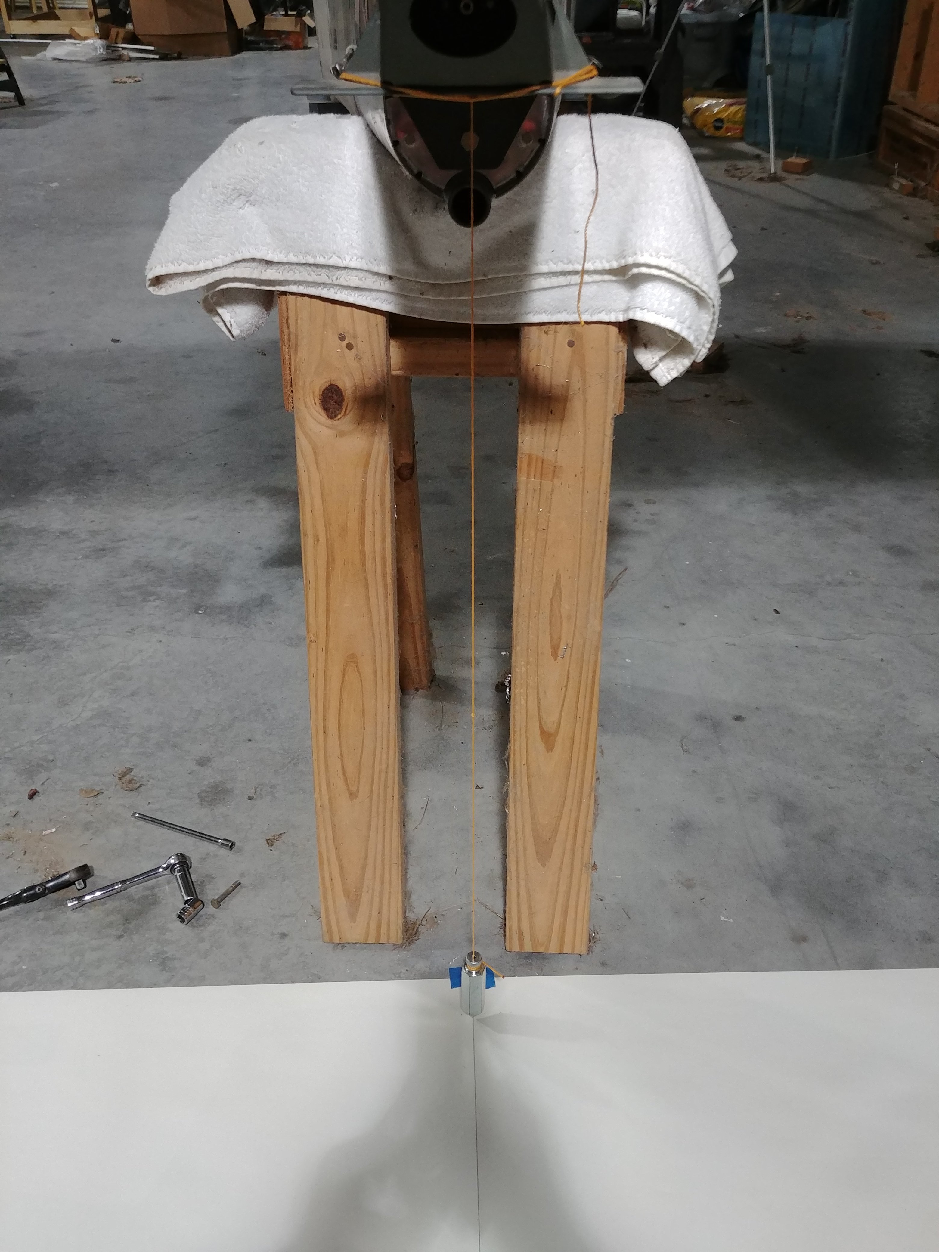
Tonight I picked up where I left off last night, with working out a method to measure rudder travel. As alluded to previously, I ended up creating an angle reference on the floor and using that, plus a plumb bob at the trailing edge of the rudder, to get things worked out.
I’d been sporadically giving this thought throughout the day, so by the time I finished dinner I had a pretty good idea how I’d proceed. The basic idea was to draw a centerline aligned with the fuselage, mark the rudder pivot point on that centerline, and then use good old trigonometry to lay out the necessary angle reference lines, which I could then compare to the plumb bob position.
This meant I needed to to some drawing on the floor, which in turn meant I needed a surface I could draw one. I also needed to be able to secure it in place, since if my reference thing moved, it’d kind of munge up the whole works. Paper seemed the material of choice, but I needed to cover an area roughly 2’x3’. I guess I could have taped together a bunch of printer paper, but that seemed annoying. After poking around the hangar a bit, I found the perfect thing. A while back when Josie and I were doing a fair bit of shooting together, I bought an enormous roll of full-size paper silhouette targets, and we’ve come nowhere near using the entire roll. One of those, turned facedown, was the perfect canvas.I folded the sheet in half to help me initially position the paper at or near the centerline – it’d be annoying if I taped the paper down and then it was way off-center and I couldn’t draw all my angle references.
Th initial centerline was laid out using the tailspring as the reference. The one complication here was that there was no good way to hang a plumb bob right on the center of the spring – so I ended up hanging it off each side at the forward and aft end, resulting in two pairs of marks. Finding the halfway point between each pair gave me my centerline reference. I meant to take a photo of this procedure, but by the time I remembered that, I’d already removed the bobs. Oh well.
Next, I needed to locate the rudder pivot point, which would be the vertex of all the angle lines I’d be drawing. To do this, I just removed the bottom hinge bolt, ran the plumb bob string through it, and got my mark made. This time I actually remembered to get a photo (note that I also had to remove the tailspring since it would have been right in the way here):
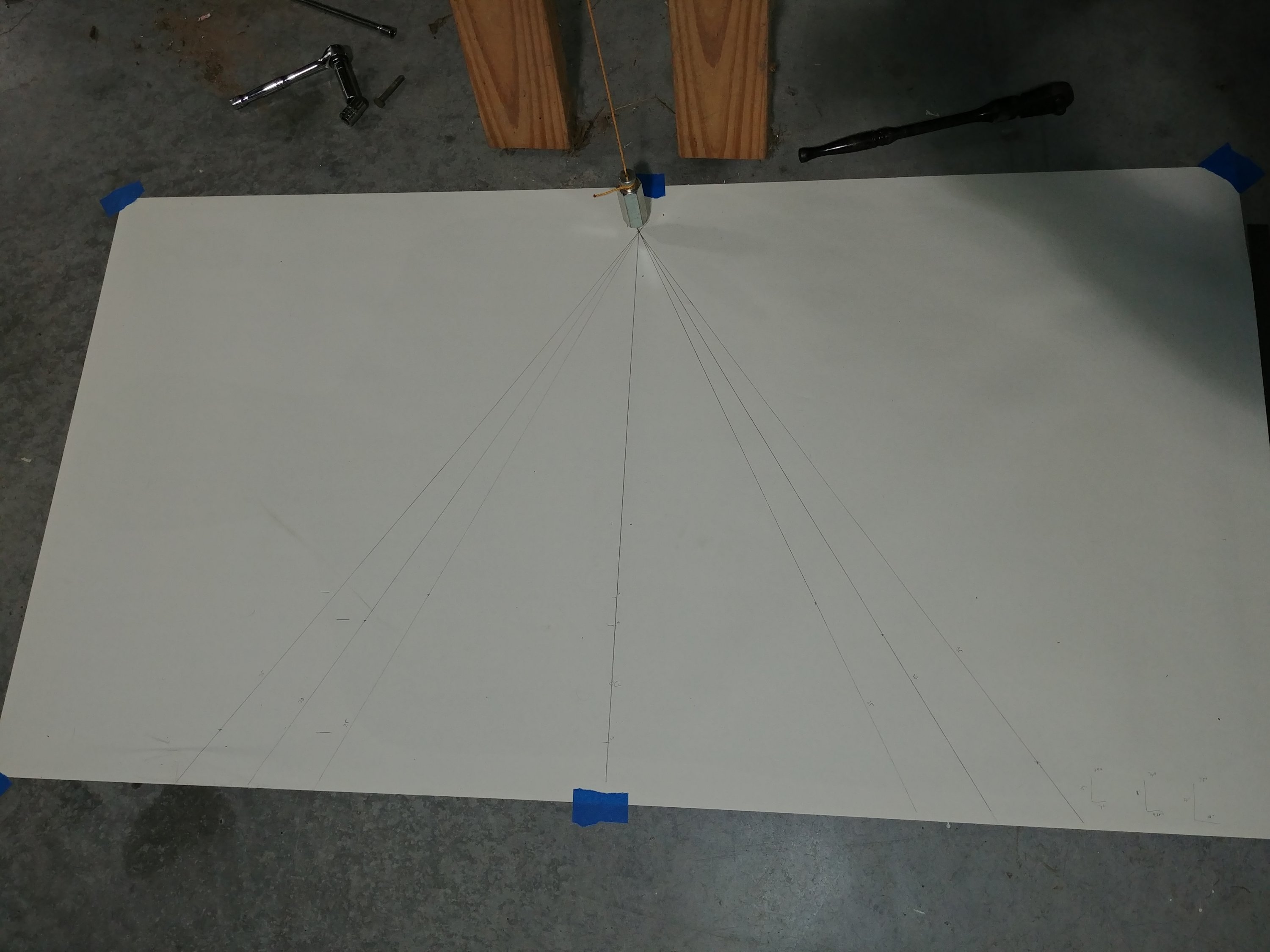
Now it was time to resort to math. The specs for rudder travel are between 30 and 35°, and for whatever reason I decided to draw a 25° line as well. The basic idea here was to identify, for each angle, a right triangle with measurements that were close enough to normal fractions to be measured pretty accurately with jut a yardstick. That was just kind of trial-and-error: get the tangent value on my phone calculator, and multiply it by successive whole numbers until the result (the other leg of the right triangle) was relatively tidy.
Next I laid out the centerline/“long-side” measurements along the centerline, and used a square to draw perpendicular reference lines at each point. Then I could use the yardstick at each point to measure the short sides of the triangles and mark those points. Finally, I used the yardstick to draw lines from the vertex under the hinge point to each of those points.
The result is a little difficult to make out since I just drew it with pencil, but I’ve got my nice reference lines:
This was where the night got interesting. With the reference lines in place, I was able to get an idea of where my travel was to begin with, and it was way off – maybe 15° in either direction. I started filing away at one side of the rudder stop, but it was tedious work in a tight space, and I hardly seemed to be making any progress. It seemed that I was going to have to remove a substantial amount of material.
This was the point where my spider-sense started to go off a bit. Everything I’d read where people talked about installing this stop, they indicated it needed hardly any trimming at all – which was not how I’d describe the work I was about to start doing. Something here didn’t add up, and so I stopped to go do some digging.
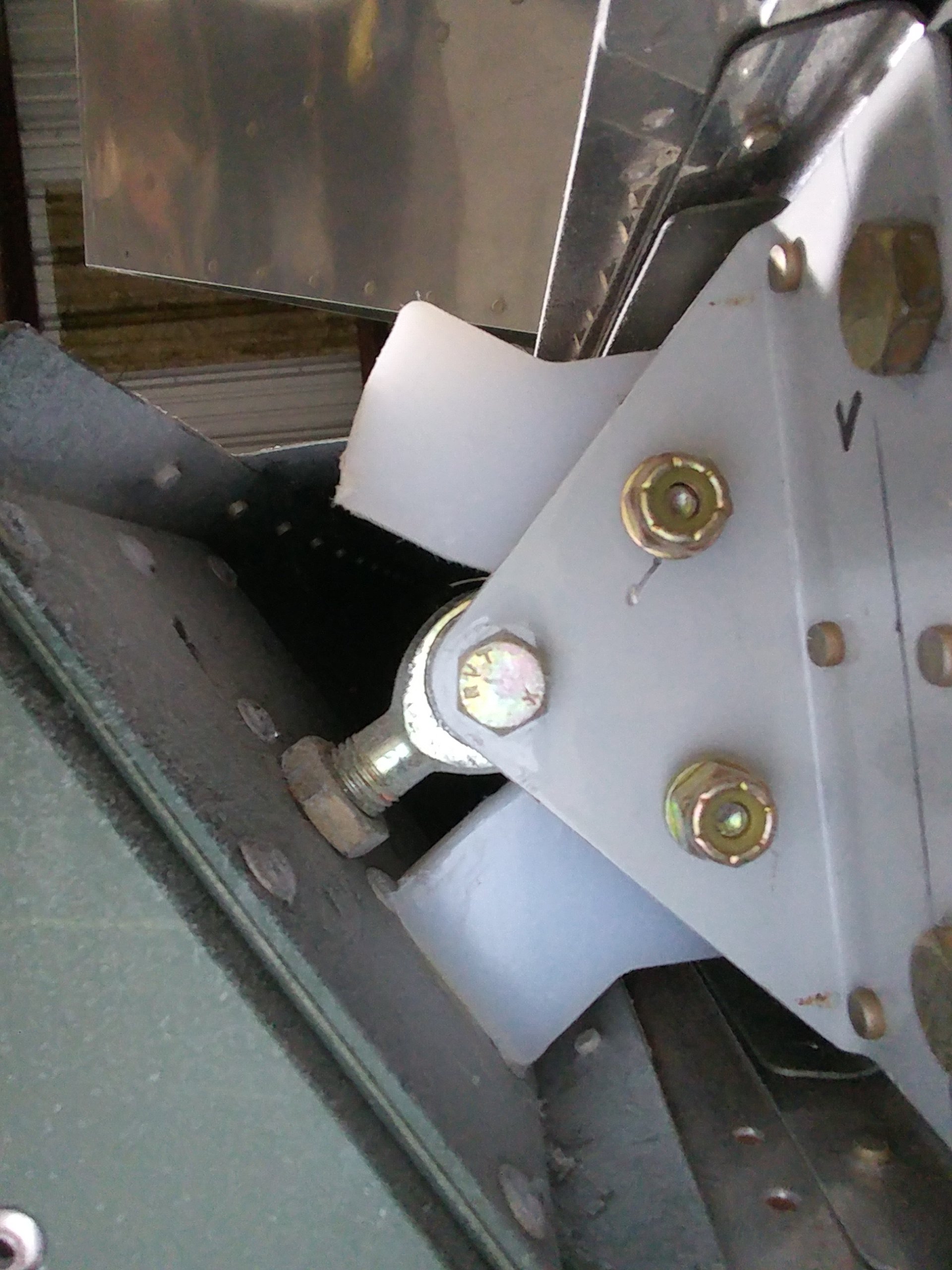
What I finally realized was that I hadn’t set the pivots on the rudder up to spec. These are simple rod-end bearings, and they’re screwed into/out of large nutplates on the rudder spar to adjust the distance of the hinge point from the spar. When I messed with these last night, I got them all aligned so the rudder could be physically mounted, but paid no attention to any actual spacing specs. And there are very specific specs laid out in the plans, and I was pretty sure the bottom rod end was threaded in significantly more than it ought to be. This would explain why my starting travel was so small – with the rod end threaded in too far, the rudder spar was closer to the rudder stop than it should be, and thus made contact after very little travel.
The conclusion was inescapable: I needed to remove the rudder again and check those bearings. I might even have to take the thing on and off several times to get the bearings lined back up again. And I was worried something would move and all that work for my angle reference would be wasted. I actually almost quit for the evening, but that also made me worry that an errant dog might tear up my angle reference too. Eventually I decided to press on.
As seems to be the case with most tasks I dread, it was no trouble at all. Once the rudder was off, I checked the bearings – the top one was to spec, the middle was a bit wonky, and sure enough, the bottom one was in too far. But I figured that if I was strategic with my bearing adjustments, I could preserve the alignment of them all and avoid more trial-and-error. The bearings are equidistant apart, so if the upper one wasn’t moving, then all I had to do was make sure that the number of turns I put on the lower bearing was twice what I put on the center one.
Three full turns got the bottom bearing to spec, so I gave the center one 1.5, then went to give hanging it a try again. And it worked – everything lined up on the first try! And now my starting rudder travel was closer to 25° – much better.
From there, it was just a bunch of progressive removal of material from each side of the stop. I chose to stop right at the 30° mark on either side. The other spec that must be met here is the clearance between the rudder and the inboard end of each elevator. I figure more clearance here is good – the idea here is preventing those two surfaces from ever coming in contact. RVs are pretty well-known for not lacing rudder authority, so I don’t see any reason to try and get closer to the max 35° travel spec.
And the rudder stop now makes nice, even contact with the spar at max deflection:
I think my next order of business will be securing the exit sleeves for the rudder cables, temporarily connecting the cables, and setting up the rudder pedals temporarily. Then I’ll be able to sit in the cockpit and make two control surfaces move! I think I could go ahead and get most of the brake system installed in the cockpit, but I’m not sure I want to do that right now. That seems more like a thing to do closer to final assembly.
If I don’t do that, then…well, I’m about as done with fuselage work as I can be right now. I do still have riveting to get done on the lower forward fuselage, so I suppose I’ll have to remove the tailfeathers once I tinker with the rudders so I can flip the canoe over again. Then I’ll have to find something else to do – probably closing out the wings and doing some fiberglass work.
I really need to get on my bank-robbery plan so I can start ordering some expensive stuff. It’s getting to the point where systems work isn’t something I can put off any longer. Which I guess means I need to sit in the cockpit and do some more chair-flying so I can finally decide that I’m happy with the panel layout.