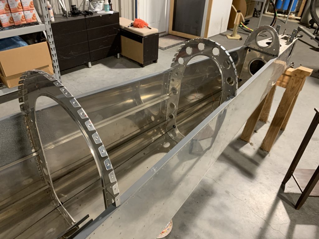
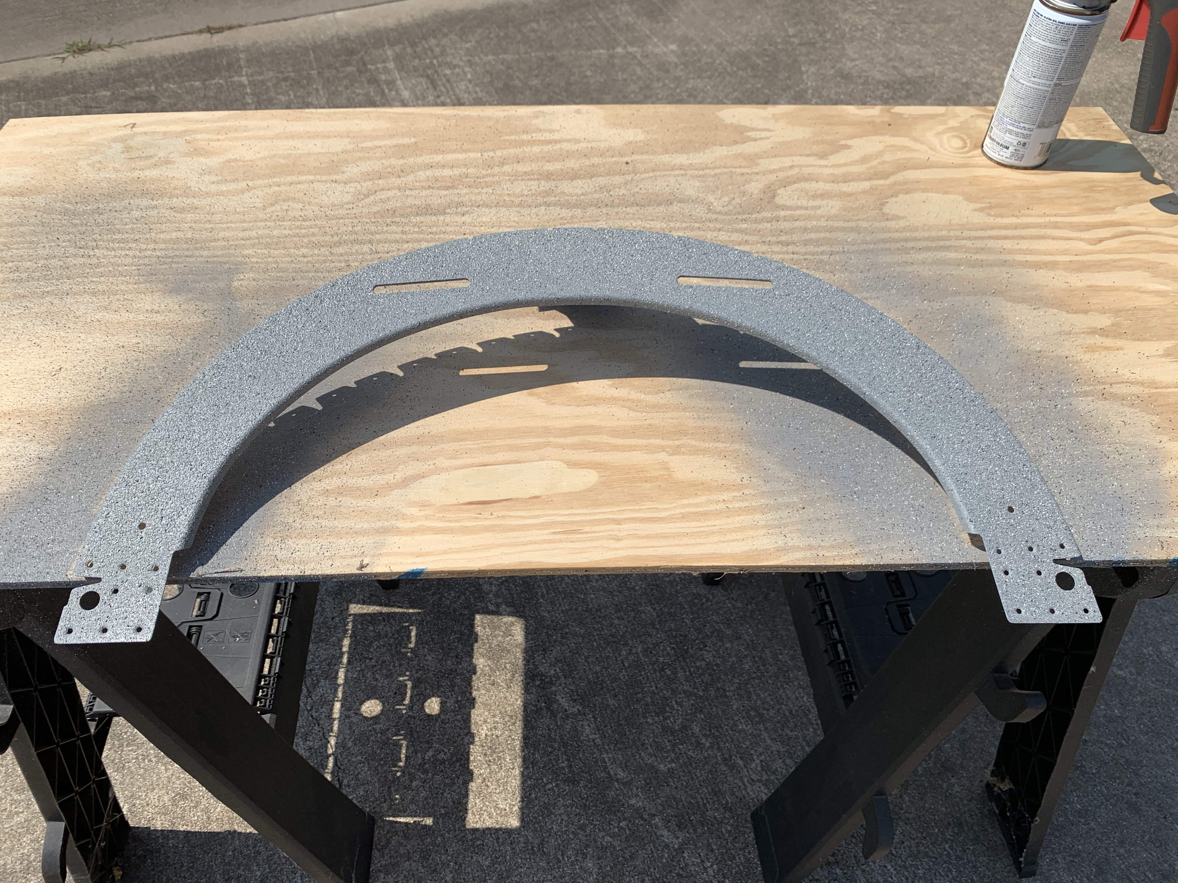
Nice productive day today, on a variety of stuff, even though I found myself needing things to complete some tasks. First up was getting the remaining bulkhead cleaned and scuffed for priming, then left out to dry while I went across the runway for coffee and chit-chat. By the time I came home, it was good and dry, so I got it primed. An hour or so later, with the primer dry to the touch, I went ahead and shot the stone texture coat, which I then left to bake in the sun. Apparently the heat and sun really help this stuff cure – previously I’ve found this paint to still be smearable a day later, but this time it was dry to the touch by mid-afternoon. It was actually dry enough that I went ahead and clecoed it in place in the fuselage, though I’m still going to wait until probably next weekend before doing any riveting, just to be sure.
Hey look, paint!
So with nothing more to do on the bulkheads, I needed a new task, and I decided to get going on the static ports. This ended up being a prime example of how vulnerable I can be to “analysis paralysis.” Before doing anything, I went inside to just look at some static system install photos, and ended up reading a whole lot of discussions about issues with static ports.
To preface this conversation, the plans method for static ports is, in the great tradition of Van’s, dirt simple – you just remove the stem from a pop rivet and bond it into a hole, then stick a tube on the inside portion. This is a touch crude for me (and others), so some time ago I bought a kit from SafeAir1 that included machined static port inserts.
Thing is, some people have reported airspeed issues with the SafeAir1 ports. From further reading, I learned that the first kits sold placed the static ports flush with the fuselage skin, unlike the pop-rivet method, which would put the ports slightly proud of the skin. Fortunately, later kits remedied this and left the ports similarly proud, and this is the type of port insert I have. Of course, there were still people reporting airspeed issues with those ports as well. Some people went so far as to install the port inserts on the outside of the skin, but still other people opined that this might cause errors due to being too proud of the skin.
Long story short, I could have spent all day trying to figure out the exact right way to do static ports, but in the end I was able to just go and install the ones I had. It seems that if I end up having any issues, they can be addressed a few different ways, so in the end I just did the thing.
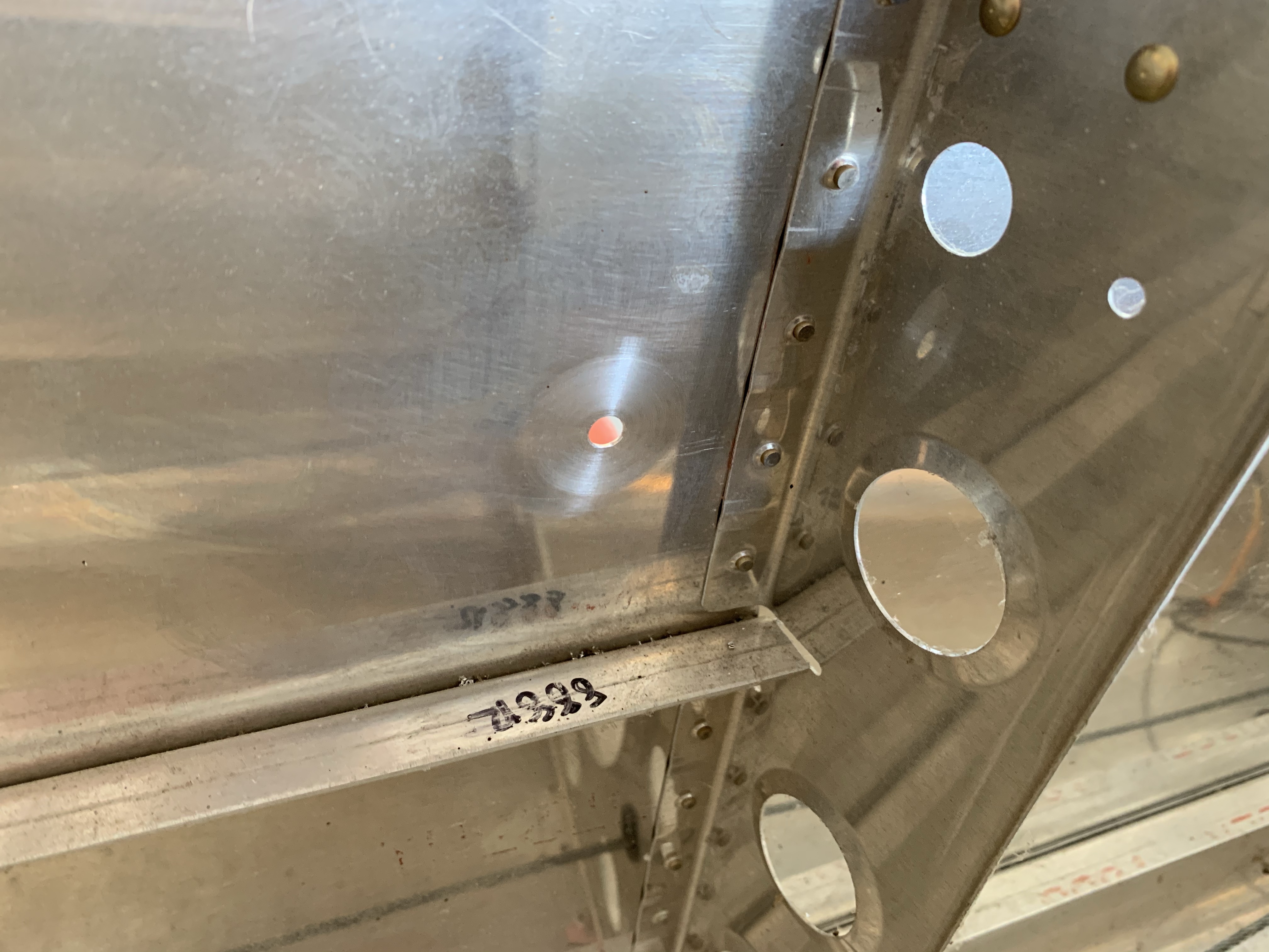
Van’s says to place the ports four inches below the longeron rivet row, and one inch forward of the adjacent bulkhead row. Since the flanges on these inserts are larger than the plans pop rivets, I moved the hole an additional quarter-inch forward, to ensure clearance with the bulkhead flanges. After measuring a few times for good measure, I drilled the 1/4” holes, one on each side of the tail.
then there was the question of how to mount these. Some people rivet them, one people bond them, some people who really like to combine belts and suspenders do both…I decided I was just going to bond them. If it’s good enough for my fresh-air scoop forward, it’s good enough for this. So I scuffed up the mating surface of the inserts, as well as the mating area inside the skins:
Here, though, I hot a roadblock: I don’t have any epoxy on hand. So much for bonding these today. I actually considered going out to buy some, but that seemed like an unproductive choice, especially since I’d probably have to go into Katy to find anything. Instead, tomorrow I can just run into Brookshire when the hardware store is open.
OK, so what next? I know, I can finally install the conduit that took me three tries to buy, and work on the pitot tube heat wiring. First up was locating the conduit holes; I reviewed the Van’s guidance on placement, which OKs a location between the forward most lightening hole and the adjacent one. I picked a center location that provided good distance between the rib edge, the lightening hole, and the stiffening ridge between the holes. I was initially going to make some sort of a jig so I could locate all the holes in the same place, but had a better idea, just using the intersection of an arc drawn off the hole, and a straight line off the rib edge.
With the holes located, I drilled pilot holes and then busted out the Unibit to open them up to 3/4”:
Then I measured the conduit run (about 24”), cut off some conduit with extra length for good measure, and pulled it through the holes. I see some people report having a lot of trouble doing this when they use this for wing wiring, but I found it pretty simple to pull through. The key is to stretch it was you pull, making the outside diameter shrink a bit so it goes through the hole more easily. I pulled the conduit relatively snug between the ribs so it wouldn’t sag, which should make running wires easier. Finally, I applied RTV around the conduit on each side of the rib penetration, to stabilize it in place and prevent vibration from cutting the conduit:
All right! Next I’ll locate the pitot controller and drill its mounting holes…wait, that’s a bad idea. I’ve got wet RTV down there, probably not a good plan to do drilling above that and embed aluminum chips in the RTV. OK, we’ll move on to wiring instead.
Since I’m extending the wiring between the controller and the tube, I’ll be adding an extra pair of terminals, which will need to pass cleanly through the conduit. This is particularly important, since my plan for dealing with the service loop of wire and pitot line will be to pull the slack out to the wingtip and secure it there (as opposed to letting it just sit loose in the wing bay).
Problem is, as supplied, the terminals both on the controller and tubs sit right beside each other, which would make for a very bulky spot in a snug conduit:
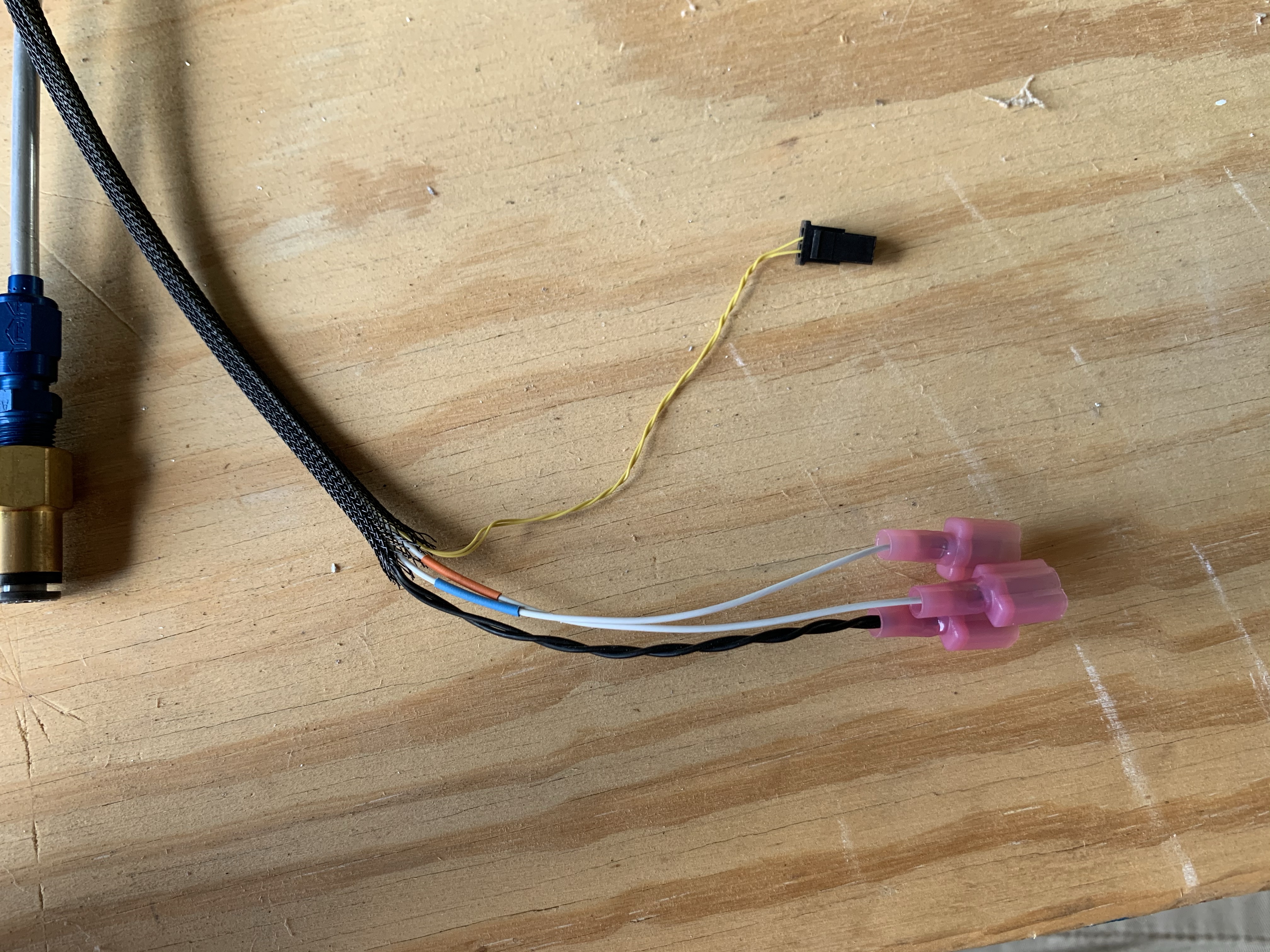
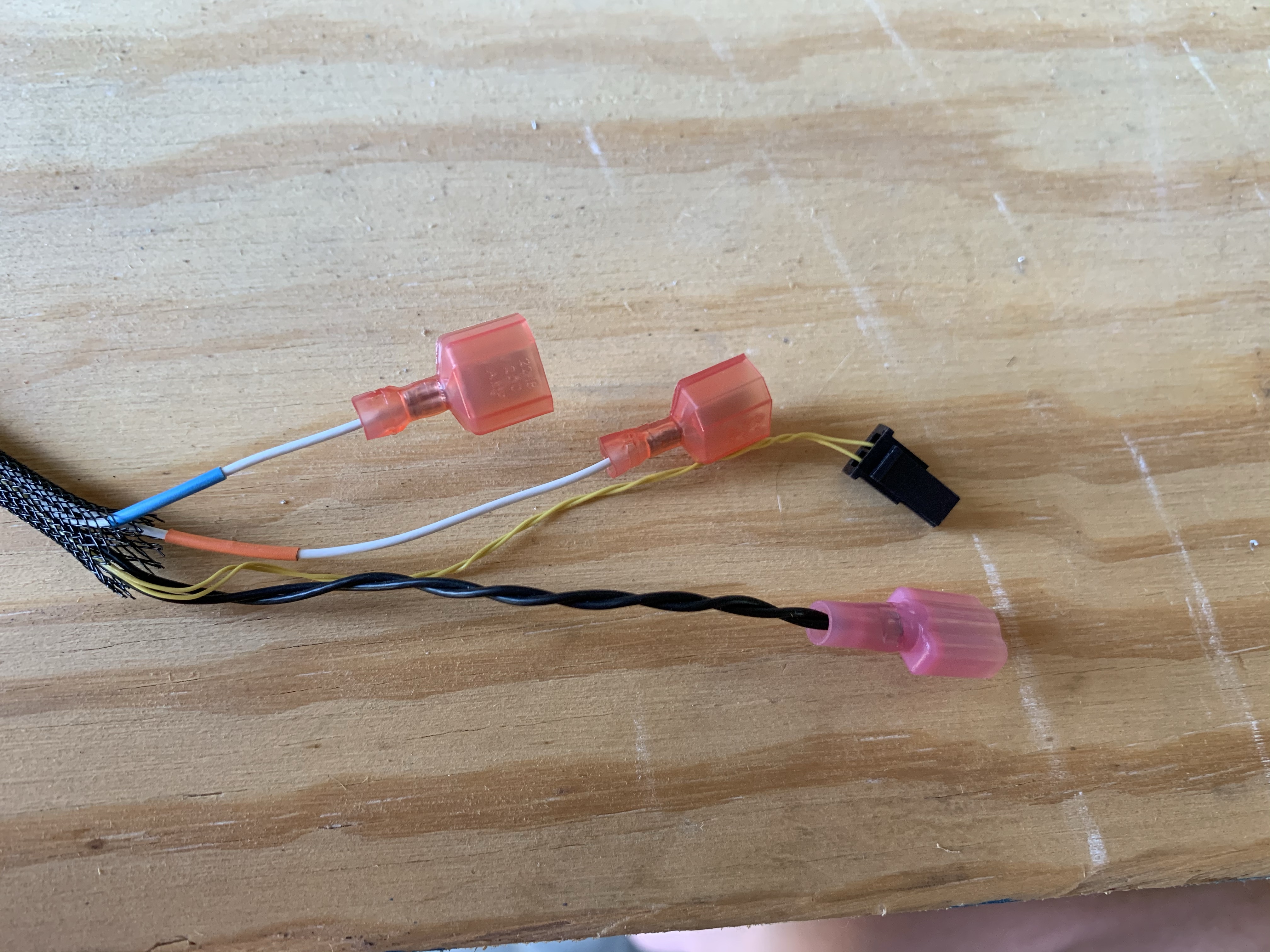
So I basically re-terminaled both the controller and pitot harnesses, staggering the wire lengths, which will allow the whole bundle to be slimmer. Once it’s assembled, I expect to wrap both joints in silicone tape or something just to help smooth them out even more. Here’s the same harness from above after trimming:
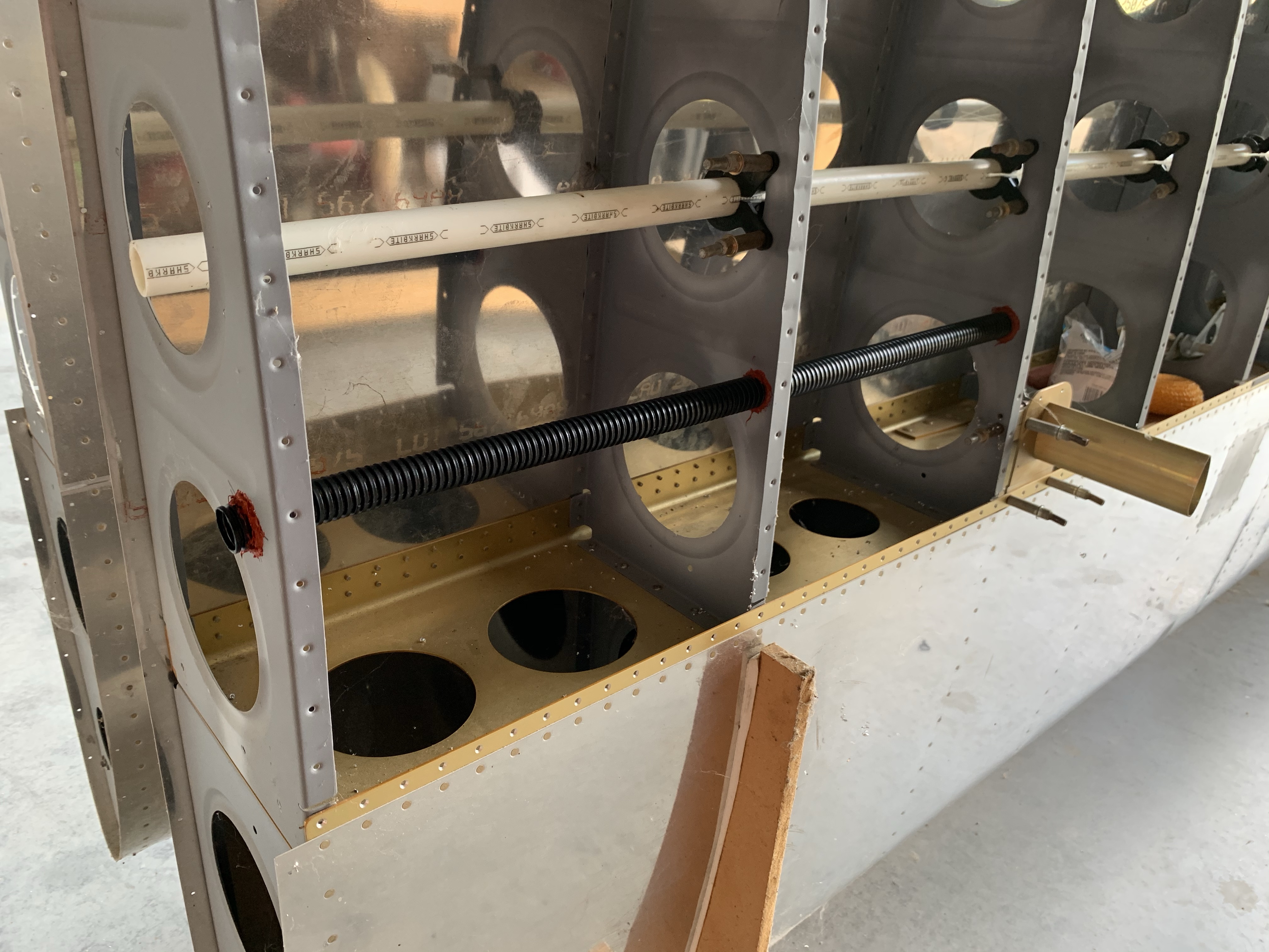
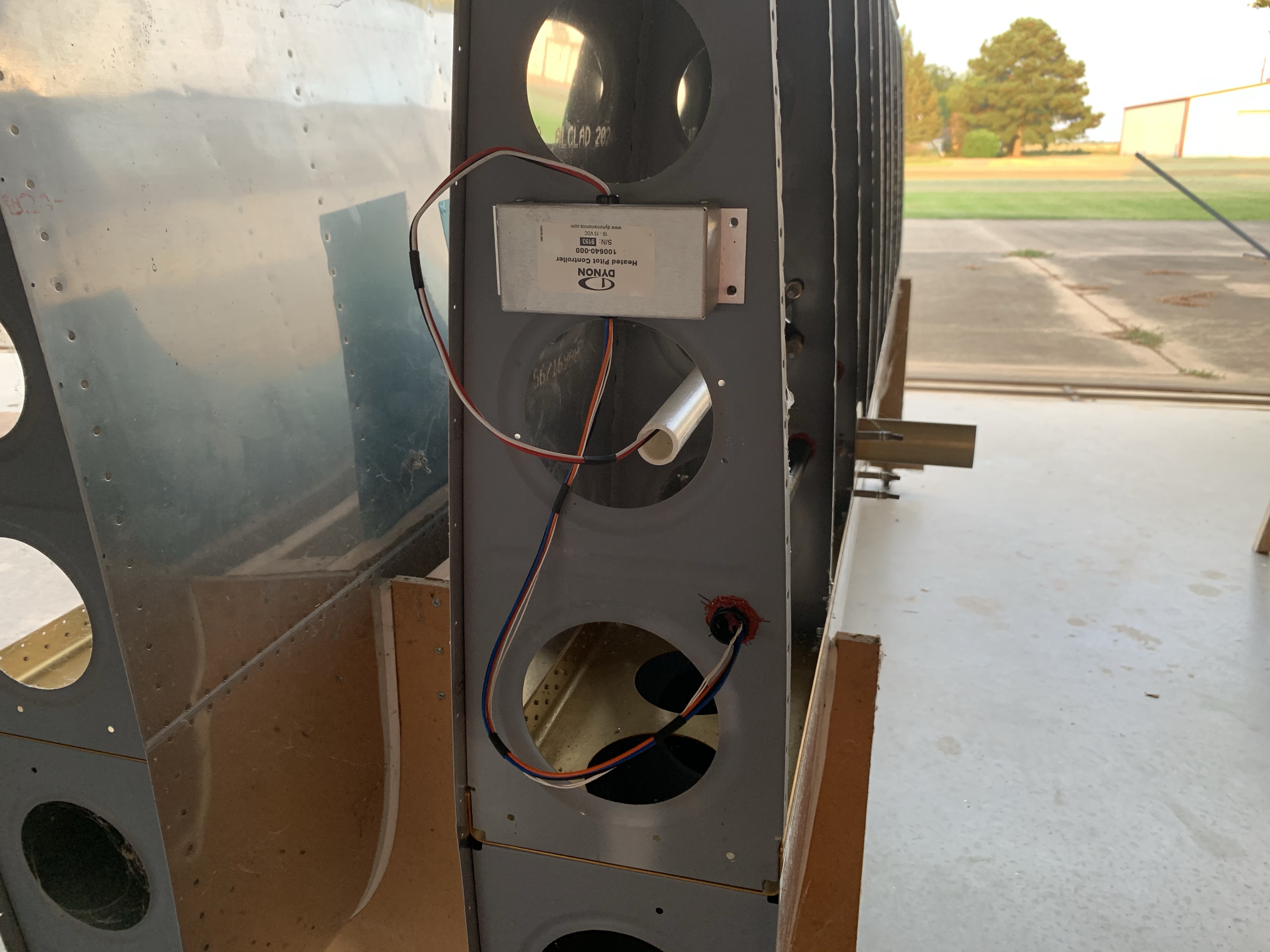
OK, now the RTV is pretty dry, so let’s get that controller located. To make this a little easier, I transferred the shape of the controller base into thin scrap plywood and thus made a template. I used the template to locate the first mounting hole, checked the actual controller in place with that hole, then used the controller itself as the template fo the other three holes. I considered going ahead and putting in the nutplates here, but for the moment I think it’s actually easier to use clecoes to temporarily mount the thing. Here it is with the two wiring runs roughed up: the feeds from the wing root coming out the white PEX conduit, and the harness going to the pitot tube going into the black ribbed conduit:
Finally, I had everything in place where I could make the extension harness that will go through the conduit! Well, actually not, it turns out. I only have red and black wire in the gauge needed for this run. Black isn’t an issue, since that’s the actual color of one run, but the other two are blue and orange. I’m not OCD enough to need the colors to actually match for those, but I do want to use an acceptable generic color, which is white. Red implies a power run – which these are, in a way, but I don’t like the ambiguity. I’d rather match the wires on the pitot tube harness, where there’s one black wire, and two white ones with heat shrink color-coded to match the controller wires.
So yeah, I need to order some wire to make this extension harness. And I guess colored heat shrink as well, but that I already found on Amazon, so that’s easy. Not sure where I want to order the wire from, I think I’ll be figuring that out tonight.
Hopefully tomorrow I can get those static port inserts bonded; if so, then I can go ahead and get the static line routing in place between the two ports. Just one more little thing.
I’ve also been thinking about my other conduit runs in the fuselage. I think I’m going to want two runs under the seat floors: the right side can house the wiring harness going to the aft avionics bay and tail, and the left one can route the pitot and AOA lines back to the ADAHRS. The other fun thing is the conduit I’d intended to run in the tail; if I run it through the holes I originally planned, it’ll exit into he baggage area, which I don’t want. Instead I think I’ll end up with a curved run, starting low in the bell crank area and ending up high at the tail. The challenge here is that the conduit run will go around a longeron, and I’ll need some way to keep that contact from wearing through the conduit over time. I’m not actually sure that this idea will work…another thing to think about…