Fuselage

Fuel pump and filter mounting

OK, not a lot done tonight. Tasks like this make me understand old sayings like “90% done, 90% to go.” Things move along pretty quickly when you follow the plans, but when you get to something where you have to figure things out yourself, it’s amazing how much slower you have to go.

Anyway, tonight I countersunk both mount brackets and riveted them in place. Next, I mounted the filter and pump in place, along with the fuel selector, then spent a whole lot of time staring at everything and trying to envision how the lines would be routed. One of the obstacles I ran into tonight is that I can’t find the adel clamps I need to use to route the line from the left wing across the cockpit to the fuel selector. There’s a bag with an assortment of clamps, but none of them are the right size. And reviewing the contents of the hardware bags, none of them list the proper clamp part number. I hate to make an order to Spruce just for four stupid clamps, but it may come to that. If I can’t find the things, I guess I’ll move on to tinkering with the rudder pedal assembly or brake lines or something like that.

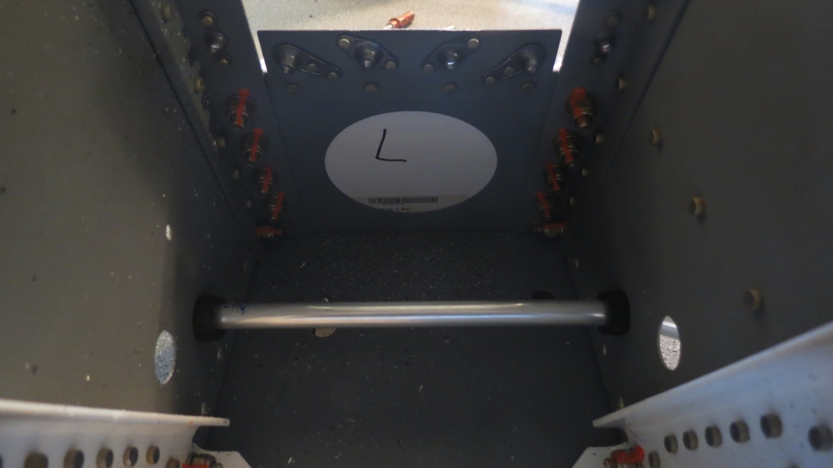
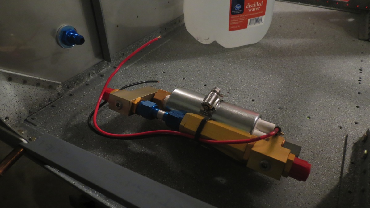
Anyway, here are a couple photos; Here’s the fuel selector clecoed in place with the fuel filter clamped to the floor beneath it:

IMG 6758

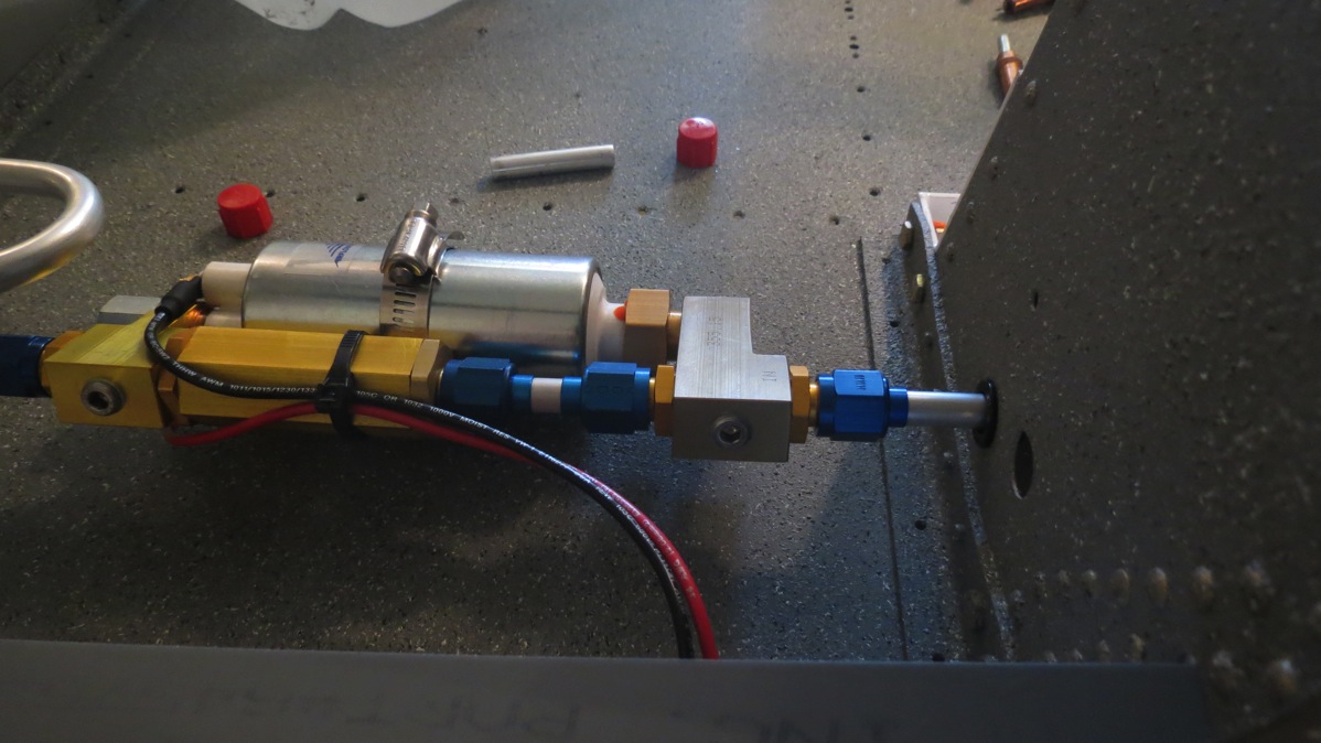
And the fuel pump clamped in place just behind the firewall:

IMG 6755

I’m a bit torn about how to orient the fuel pump. Currently it’s mounted with the inlet forward and the outlet aft, so both lines would have to make 180° bends and sort of go the “long way around.” Doing it this way eliminates the concern of trying to carefully align the aft part of the pump with the prepunched hole in the tower that the line will pass through. It seems to me it would be challenging to get the line bent just right in that area. On the other hand, it means using an extra 2’ or so of tubing, and I don’t know how much excess is provided – and I’m sure I’ll ruin some lines along the way here. On the other other hand, it’s not as if it’s impossible to buy more tubing if needed…I dunno. I’ll have to keep thinking about it, I guess.

Posted in Fuselage | Hours Logged: 1

Made a fuel line

So yeah, it’s been a while again. I went for a track day at MSR Houston a few weeks ago, and during my second Sunday run session, I had a clutch failure in the car. After looking at part prices, I decided to replace the clutch myself instead of going to a shop – which kind of occupied a lot of my time. But the car’s back up and running now, so it’s finally back to work.

After reviewing the fuel system layout and considering the various lines that needed to be made, I eventually took the cop-out route and just made the easiest one first, the line between the fuel pump and the firewall fitting. Nothing too complex, just two 180°-ish bends, but the bend planes had to be about 90° apart to get things to align properly. And of course, the first flare I made, I’d forgotten to slide the B-nut and sleeve on the line first, so I had to cut it off. Good thing I still had extra tubing on the other end to work with…

Here’s the finished product:

IMG 6763

I can already see that this is going to be a somewhat tedious process. The line between the filter and pump will probably be the worst; it has to pass through the gear tower, and from the looks of things, I’ll have to flare at least one end of it in place, which should be lots of fun…I may go ahead and deal with this line next, just to get the annoying task out of the way. I also need to fab up a template to help position the lines out to the wings. The forward side skins have a passthrough hole cut in them, so I’ll reproduce that in a piece of sheet I can cleco in place.

Posted in Fuselage | Hours Logged: 1

More fuel lines

So, it turns out that bending hard lines is…somewhat challenging. I kind of knew that would be the case, but I was maybe a bit too buoyed by the first line I made a couple days ago. Suffice it to say that I made a lot of scrap material today. Still, I almost got all the lines done with the material I had on hand, but for one final annoying foul-up…more on that in a bit.

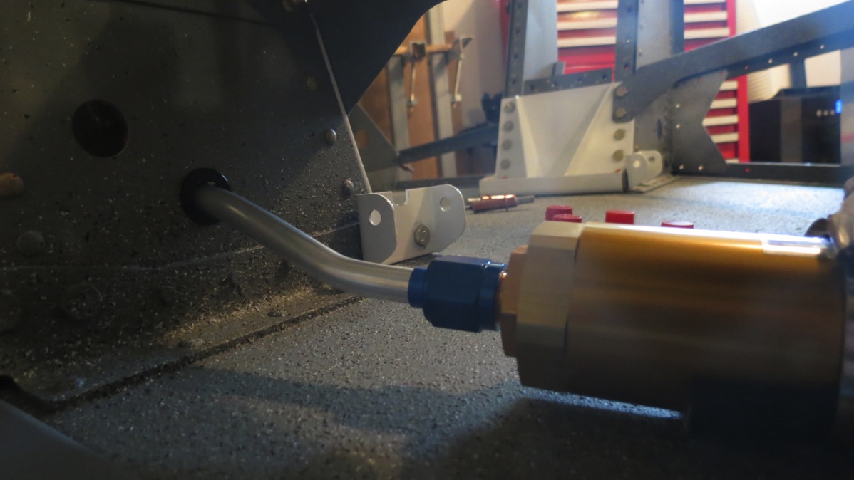
I started out trying to make the line between the fuel selector and the filter, which wasn’t exactly sensible, since the line between the filter and pump was going to be the annoying one, but I was kind of punting on that particular problem. Except I managed to foul up two attempts at the select-filter line in a row, for various and sundry reasons. Then, I oddly decided that maybe the filter-pump line was a better idea. And surprisingly enough, it went pretty well. I knew going in that I would have to flare at least one end of the line in place – the flares won’t pass through the snap bushings where the line goes through the gear towers. Fortunately, I didn’t have to do the actual bending in place; that would have been no fun at all. I actually got this one done on the first try; despite the annoyance of going through the tower, it’s a much simpler line than the other ones, with just two very slight bends.

Out of the filter…:
IMG 6774

…through the tower…:

IMG 6776

…and into the pump:

IMG 6780

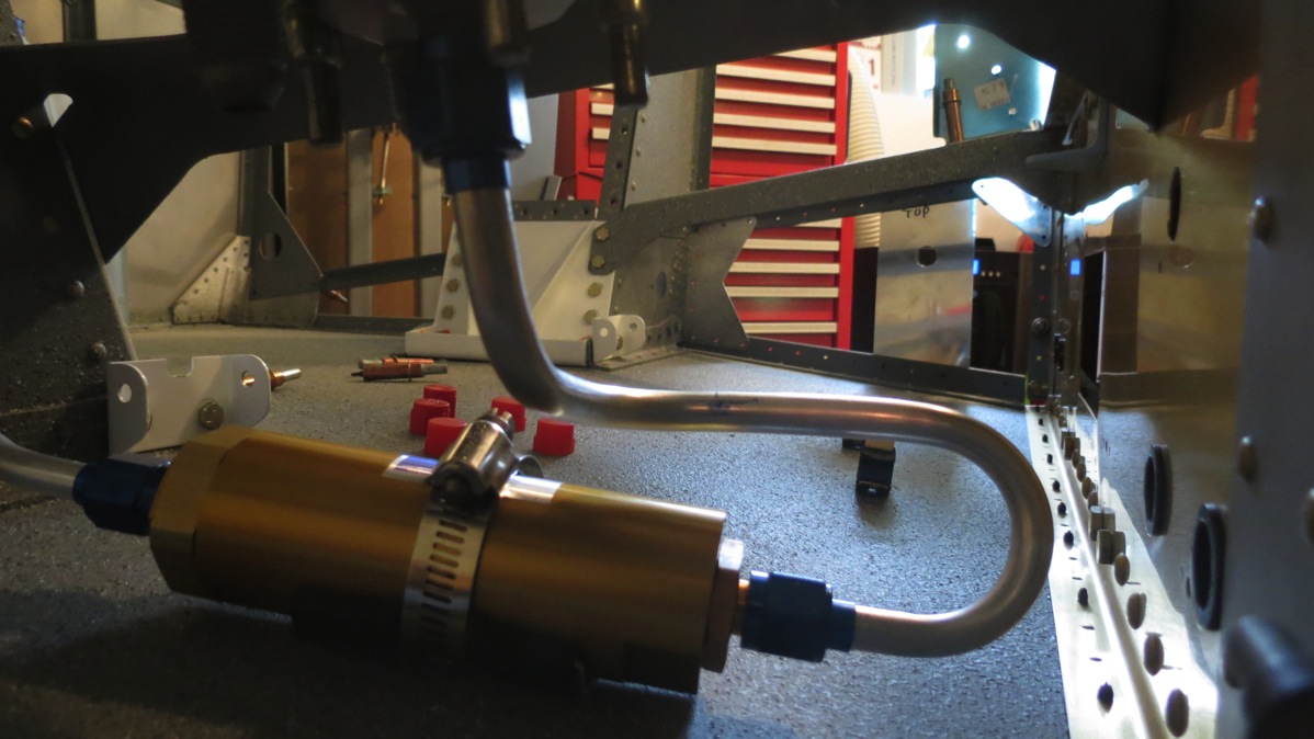
Next up was that pesky selector-filter line. This time I took a few moments to figure out the dimensions of the bends from my tubing bender – approximate radius and circumference. This allowed me to plan the line a bit better. A fun thing to consider while working on this is that the line from the right tank will be attached to the center section web in close proximity. To simulate the presence of that line, I put a length of tubing into a coupe of the adel clamps that will hold the actual line – this way I could be sure the two lines wouldn’t be rubbing or anything undesirable like that.

The finished selector-filter line:
IMG 6773

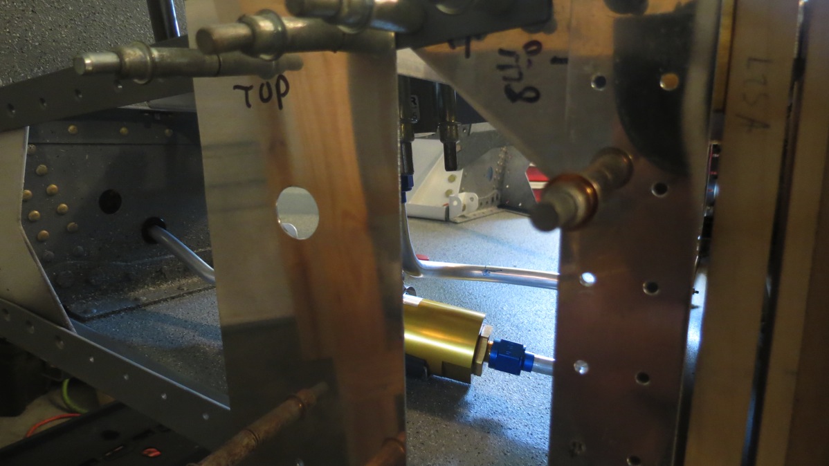
Then there was the line to the left tank. Here, I took a few minutes and made a template from one of the forward side skins so I could approximate the passthrough hole for the fuel line:
IMG 6769

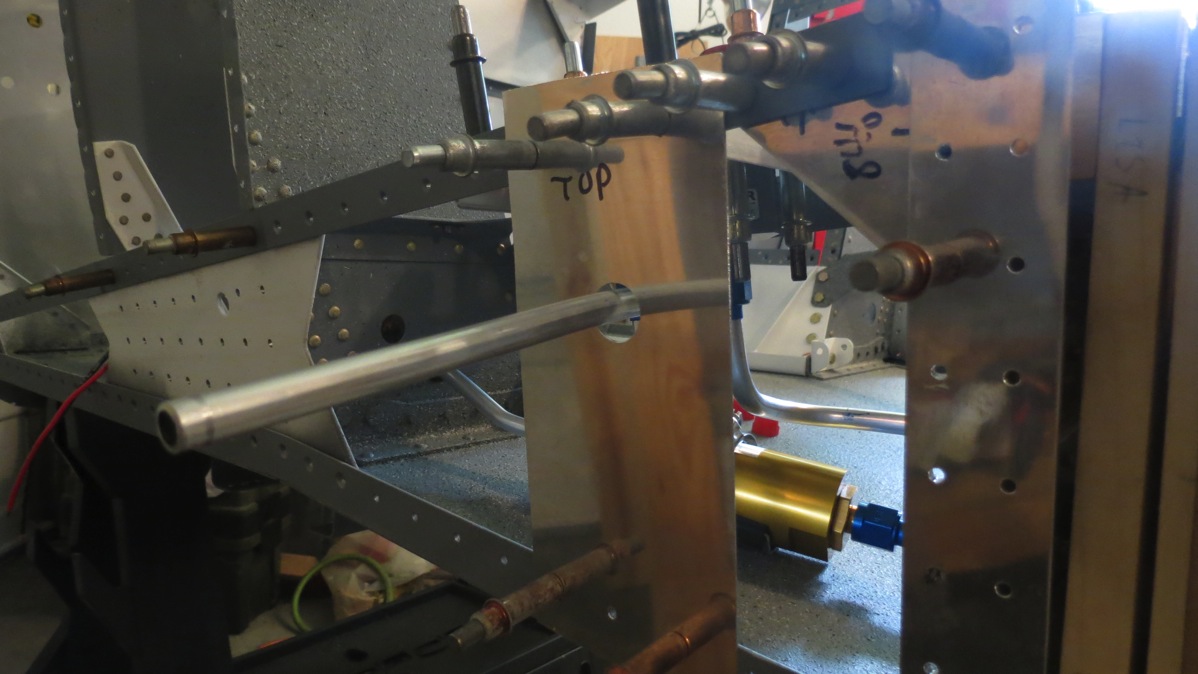
The line here was pretty simple too; just down from the selector, a 180° bend back up to the passthrough, and a 90° bend to go through the hole. My previous note of the bend radius made this actually match up on the first try:
IMG 6771

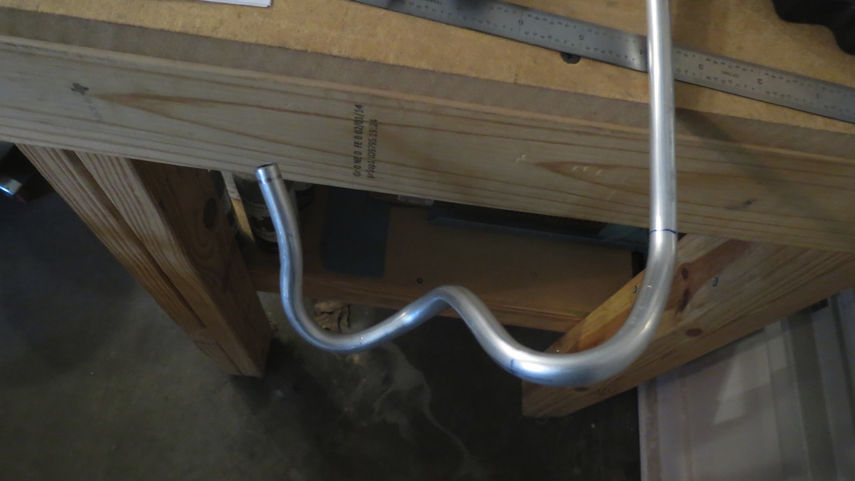
That only left one more line – the long one over to the right tank. Amazingly enough, despite my early mistakes, I still had enough tubing left to make this line. So I measured everything carefully, plotting out my first couple bends to get from the selector back to the center section web, did my bends, and…I forgot to subtract the bend radii. With the line against the center section, the end by the selector was at least 1.5” too far forward. I tried to salvage the line by adding some extra bends to account for the extra length, but it was too much – eventually I started to collapse a couple of the bends, and so I admitted defeat. This is the modern art masterpiece that resulted from trying to salvage that line:
IMG 6782

So I’ll have to order some more tubing from Spruce this week. The good news is that this stuff is super cheap, like 75 cents a foot.

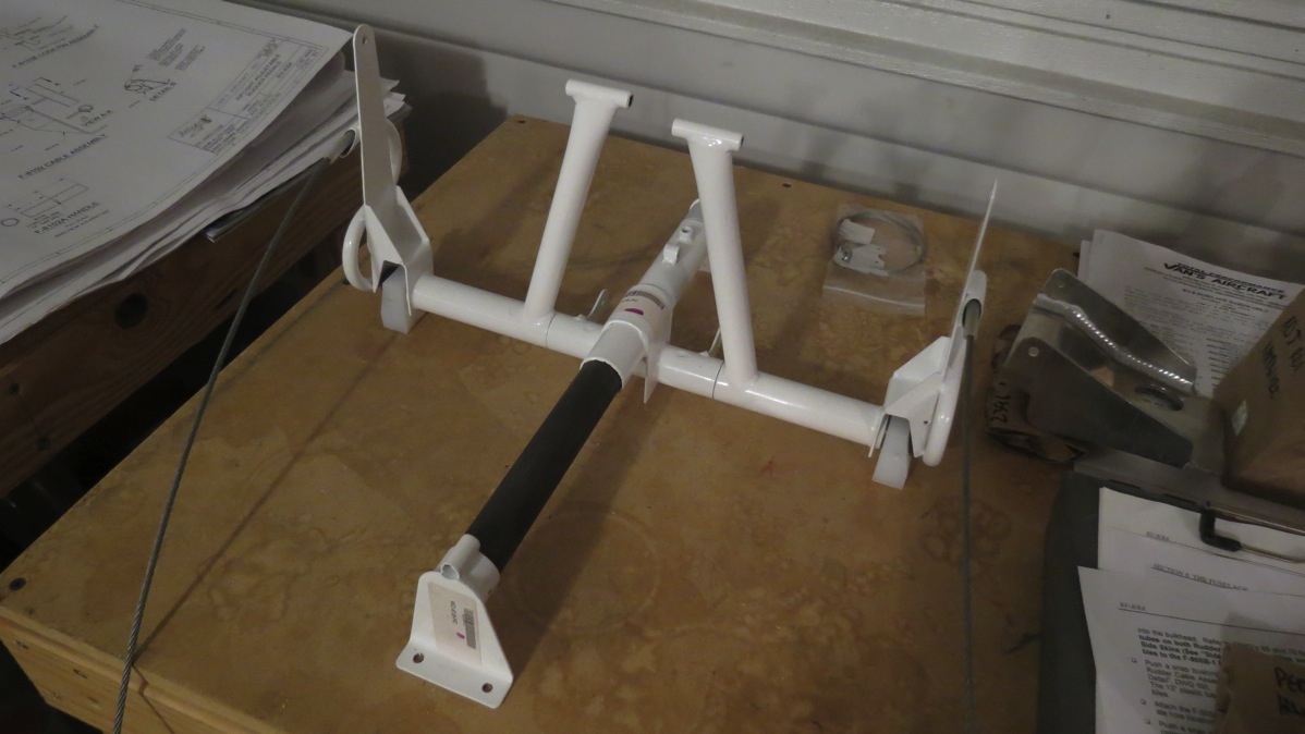
I wasn’t quite ready to quit for the day, so now what? I could either keep with the tubing-bending fun and work on some brake lines, or I could start paying with the rudder pedal assembly. The latter seemed like a lot more fun, so I started a full-fledged hunt for all the required parts. Rather than just jumping into the assembly instructions, I started roughly assembling the parts just to get an idea of how everything went together. But I could only go so far without having to final-drill some holes. I’d hoped to at least get the brake pedals in place so it looked like something…but they needed final drilling, So I just ended up with this:
IMG 6784

The first actual assembly step was to final-drill the mounting bole holes in the slide bar to #12, so the assembly could be temporarily bolted into the fuselage. Well, I got exactly two holes drilled on the drill press; on the second one, the piece slipped, and the drill bit caught and promptly detonated. The part turned out OK, but obviously I needed a new drill bit. Oh, look – it turns out that was the only #12 drill bit I have. I had extras of literally every other size except for #12. Well, that pretty much put a stop to work on the rudder assembly – it seems that every hole in this thing is #12.

I tinkered a bit with the brake system, looking over the line layouts and gathering parts, but ultimately I didn’t really get anything done. I’m going to have to modify the line routing here a bit, so I’ve got to figure that out. The plans route the brake lines through the second lightening hole from the top in the gear towers – but that hole is in the middle of the removable plates I made. Having a brake line go through the would kind of put a kink in the whole “removable” thing. So I guess I’ll have to route the lines a bit higher and go down through the top hole.

Anyway, I’m going to sleep on that and give it a whirl tomorrow, I suppose. I’ve done enough damage for one day.

Posted in Fuselage | Hours Logged: 6.5

Indecision and time-wasting

Well, I didn’t get a lot of useful work done tonight. I’d vaguely intended to muck around with the brake lines and/or fuel vent lines. I didn’t have the fittings I ordered for the brake lines, so I decided to look at the vent lines instead. I’ve kind of been on the fence about how to handle the vent line anyway. The “factory” method has the vent lines enter the gear towers, loop up as high as possible, and then exit out the bottom of the towers, just in front of the landing gear. However, some builders have been taking a different approach, as used by many F1 Rocket builders. That method is to simply bend a series of loops in the wing root and then have the vent exit out of the fairing between the wing and fuselage. This method is much simpler, though there’s speculation that it’s more likely to spit fuel overboard on the ground on a hot day.

Anyway, I’ve been going back and forth quite a bit as to which method to use. Tonight, I got to looking at the vent line routing, and noticed that the exit holes are prepunched in the gear covers. This tiny bit of information was enough to make me decide to do the factory vent line routing. So I measured, planned, cut, bent, and flared, and made my first vent line. I wanted to go ahead and cut the exit portion of the vent line to fit the nice JD Air vent pieces I bought a while back, so I was going to fit those to the gear covers – except they’d be covering one of the screw holes that attaches the gear cover. And the vent has to be installed before the cover. This seemed like a clear no-go, and a quick search of VAF confirmed the problem.

That left me with a pretty simple choice: use the factory routing without the nice vents, or use the Rocket-style routing with the vents. I decided to go with the latter. Tat meant no more vent line work – time to move on to the brake lines.

The brake lines are another interesting item. By the plans, the lines enter the gear towers through the middle lightening hole, but that hole is part of my removable covers. After doing some reading, I decided to add a bulkhead fitting to the gear towers, and split each brake line into two parts – one section from the cabin center to the exterior of the gear tower, and another running inside the gear tower. I’d been unsure of where to locate the bulkhead fitting, but my vent line decision gave me a nice spot – at the top of each tower was a prepunched hole, which would normally mount an Adel clamp to hold the vent line in place inside the tower. It was in a good location for the bulkhead fitting, so I got the unibit and opened each hole up for an AN bulkhead fitting.

Then I went to work bending the first line. I was quite proud of the results:

IMG 6785

But then I realized there might be a problem. The tops of the towers are pretty narrow, and in addition to the length of the bulkhead fitting, I can only put a bend so close to the flared end of a line. I bent a piece of scrap line and flared it to use as a test, and the results were…displeasing:

IMG 6792

IMG 6789

Yup, that’s not going to work, unless I add some some chipmunk bulges to the forward side skins or something. So I basically have three alternatives here:

1. Reverse the bulkhead fitting. This would put the elbow portion inside the gear tower, so clearance in there wouldn’t be an issue any more. The downside here is that the bulky part of the run – the big 180° bend to the fitting – would be inside the tower. This wouldn’t be visible – this area sits behind the panel – but then that’s more stuff in what will probably be a crowded area. The good news is that after taking a look at the panel piers, I don’t think this will interfere with any major components.

2. Remove the bulkhead fitting entirely, insert a snap bushing, and run a single brake line instead of two. This wouldn’t take up a lot of space, but it would basically make it impossible to replace the line down the road. There’d be no way to extract it without cutting it. Though, if that happened, I could revisit the bulkhead fitting idea then. But if I’m going to eventually probably have to do a bulkhead fitting, why not just do it from the start?

3. Figure out a way to run a one-piece line through the upper lightening hole. I think this would be cumbersome and still difficult to replace down the road if necessary.

So that’s where I stand right now. #1 sounds like the best option to me, but I’ve already made enough ill-informed decisions tonight. I’m going to sleep on this one before committing to anything.

Posted in Fuselage | Hours Logged: 2

Last fuel line

Today I got my shipment from Spruce, which included a new stock of 3/8” tubing for that last remaining fuel line. I decided to work on that and continue punting on the whole brake line issue. I hacked up my previous failed attempt at this line and used it to prototype the shape of the finished product. Amusingly enough, there was actually still enough tubing to have made this line without the new stuff – but that’s OK, because this prototype was still not quite up to my standards. But it made a great template for the final product.

Here’s where the line will exit the right side of the fuselage. Note that there’s a 90° forward bend here, unlike the straight-out exit of the left line. This is to accommodate the flop tube in the right tank. The regular fuel pickup exits the tank near the back, but the flop tube exits up at the nose of the tank. So this line must run forward, parallel to the fuselage, and through the inboard tank mount to connect to the flop tube fitting. There will be a union fitting here to connect the short line up to the pickup fitting. This is presumably to ensure that this line can be removed after the fuselage is complete if necessary. (The B-nut isn’t visible here because it wouldn’t fit through the hole in my template. Don’t worry, I didn’t forget it.)

IMG 6799

Same location, from inboard. This shows how the line is attached to the center section web to cross the fuselage, and then there’s a jog to get it to the proper location to exit the fuselage:

IMG 6801

And finally, all the lines in place under the fuel selector valve:

IMG 6797

IMG 6794

Hopefully tomorrow I should get in my parts order from Van’s, which will contain the fittings I need to do the brake lines. I needed two more 90° bulkhead fittings for these lines; when I worked on them last night, it was with the knowledge that I’d only be able to have one line in place at a time. Once I have all the fittings, I can put everything in place at once. If I don’t get the order from Van’s, I can always go back to the rudder pedal assembly, since I got my #12 drill bit restock in today as well.

Posted in Fuselage | Hours Logged: 1.5

Brake lines

Welp, looks like I’m done bending and flaring tubing, at least for a while. Actually, I don’t think there will be any more hard lines to bend until I get around to attaching the wings and hooking up the fuel system. Today I took care of the hard brake lines, which run from a junction point under the forward baggage bulkhead out and down through the gear towers. When I did these before I discovered that I couldn’t use the bulkhead fittings like I’d wanted, and would have to reverse them. Things got even more complicated this time out. For each side of the aircraft, there’s a 90° bulkhead fitting at the junction point, and another 90° bulkhead fitting at the base of the gear tower. Except there are only two 90° fittings in this kit. Without the fittings at the base of the towers, these brake lines have to be left half done, which kind of kills my goal of finishing them while the forward side skins aren’t in the way.

Fortunately, I have to extra 90° bulkhead fittings, which I ordered to use where the lines pass through the gear towers. I also have two extra 45° fittings which would have been used for the vent lines, had I gone with the factory method. So I decided to use the 45° fittings for the gear towers passthrough, and repurpose my extra 90° fittings for the floor passthrough. With that settled, there was just a lot of bending to do. The lines inside the gear towers are pretty straightforward, but the lines from the towers to the junction are a little more complex, mainly because of how far out they have to stick due to me reversing the fittings. For both of these spots, I ended up making a first pass at a line, which ended up messed up, but worked as a prototype for the actual line. This has been a kind of common theme actually…

Anyway, here are the lines from the junction to the towers:

IMG 6803

A close look at the gear tower passthrough end:

IMG 6804

And one of the lines inside the towers:

IMG 6807

Finally, here’s the large pile of scrap leftover after all this tubing work. Not pictured is the 3’ long remains of my first attempt at the long fuel line across the fuselage:

IMG 6809

So tomorrow it’s back to the rudder pedal assemblies. I suspect those will be an all-day job (maybe more), but after that I think I’ll be done mucking with systems for now, and I can get back to putting the tailcone together.

Posted in Fuselage | Hours Logged: 4

Pedal assembly

Today started with some general cleanup. I still had the pile of tubing scraps from yesterday’s photo op, in addition to all the tools and various other related stuff lying around. So it took about half an hour to get to a point where the workbench was usable again.

The pedal system is relatively straightforward as systems go, but still mildly time-consuming to construct. First, small pilot holes are final drilled to #12 for the mount points to the forward floor and firewall. Then the assembly is bolted in place temporarily and mount holes between the slide bar and end socket are drilled. The whole assembly comes out, stuff gets deburred, and then it’s time to drill the assortment of position holes in the slide bar. These hole determine the possible positions of the pedals.  The plan method here is a bit convoluted for my taste; they want you to drill the forward- and aft-most positions, disassemble everything, mark the positions of the remaining holes, reassemble, and then align the pedal with each mark and drill a hole at that point. It seemed a lot easier to me to measure the length of travel, mark the exposed slide bar at appropriate intervals, and just slide the pedals to each new position to drill. So that’s what I did.

Here’s the slide bar marked for each position (sorry for the blurry photo):

IMG 6811

And a look at the holes with the pedals in the aft-most position:

IMG 6813

Next, the rudder pedals go in place. The pedals are retained by plastic end blocks which bolt through the rudder pivot bar; these blocks are carefully positioned and then bolt holes are drilled through the pivot bar. Disassemble, deburr some more, and then the pedals go in place permanently.

Then it’s time for the brake pedals and master cylinders. The pedals themselves are welded aluminum units, and like anything in the kit made from thick aluminum, the edges are pretty nasty. So I spent a fair amount of time cleaning up the edges. Then the master cylinders have to be prepared by installing the brake line fittings. The fittings are clocked slightly inboard to provide proper clearance:

IMG 6815

While the pivot points for the brake pedals are predrilled, the hole to connect the upper master cylinder is not. The plans call for a specific location, and note that pilots with large feet may wish to drill the holes a bit higher to avoid inadvertent brake application. I don’t think my feet are that big, but I don’t want inadvertent brake application, so I drilled the holes 1/8” higher than specified.

I actually messed up a bit here. The instructions only have you drill one pedal to start with, then put everything together with the pedals aligned, and then the hole location in the other pedal can be marked. This is to ensure that both pedals are aligned. Well, I just marked and drilled both pedals before reading this bit. But after temporarily assembling everything, the pedals still align OK, so nothing to worry about here.

Here’s the final assembly from the aft (pilot-facing) side:

IMG 6817

And from the forward (firewall) side. Note the tape over the brake fittings – I don’t want any foreign material getting in there!

IMG 6819

And that’s a good day’s work. Next up, I’ll put together the locking mechanism to finalize the adjustment functionality. I also need to finalize all the bolts and add cotter pins where appropriate, but before I do that, I want to prime and paint the pedals. I briefly considered having them anodized, but decided that just using the same interior paint as everywhere else will work. It’ll also provide a slight bit of anti-skid roughness – not enough to impede sliding my feet on and off the brakes, but to help keep my feet in position.

Posted in Fuselage | Hours Logged: 5.5

Pedal adjustment mechanism

Tonight I went to work on the mechanism that allows the pedal to be adjusted. The main part of the locking mechanism consists of six thin aluminum spacers, two steel lift levers, and a center aluminum piece to which the adjustment cable attaches to. All these parts had to be deburred, drilled to final size, and finally riveted together. Then the lock pin was fabricated from a 1/4” clevis pine; here, you just cut off the tang of the pin, smooth and chamfer the end, and insert a long roll pin into the cotter pin hole. The roll pin is engaged by the lift levers to pull the lock pin out and allow the pedal assembly to move.

With the lock pin complete, the lock assembly went into place. Pretty simple here, the mechanism pivots on another 1/4” clevis pin, with a stiff spring to keep the locking pin in place unless the release cable is being pulled. I installed the pin, bent the cotter pin, and…the pedals wouldn’t move. Apparently I made the locking pin a bit too long. So I removed the mechanism again (that cotter pin had a really short lifetime) and trimmed the lock pin a bit. That was kind of obnoxious with the roll pin installed; the first time around, I just chucked the pin into a drill and spun it against the bench grinder to get the length right and add the chamfer. This time, I tweaked the length by just filing away at the thing, and then rotating it against the bench grinder by hand to add the chamfer. It didn’t look nearly as nice as last time, but it won’t be visible anyway.

This time, with the mechanism in place (which I tested before bending a second cotter pin), the pedals moved and locked correctly. Here’s a close-up of the mechanism:

IMG 6822

That only left one more task: cutting the release cable to length and attaching the handle (just a 2” piece of tubing with a hole drilled in the middle). And this was where things went awry. The instructions are to cut the cable to “the desired length, leaving 5/8” for a knot at the end of the cable.” For some reason, I decided the best course of action was to just cut the cable 1” longer than it needed to be to clear the guide with the pedals full forward. After running the cut cable through the handle and beginning to tie the knot, I was thinking that it looked too short, and sure enough:

IMG 6823

At the current length, the two forward most positions are unusable. The main issue with fixing this problem is that the cable was preassembled, with the loop already crimped in the end and through the locking mechanism. So a replacement part from Van’s would require replacing the entire locking mechanism. I suppose I could make a new cable myself, but I’m not sure if I need special tools to crimp the loop in the cable properly. Something fun to investigate, I guess…

UPDATE: It didn’t take much research to discover that the proper tool for crimping Nicopress sleeves is…quite expensive. On the other hand, the necessary replacement parts from Van’s are about $25. It’s not really imperative that I get these parts in anytime soon, so I think I’ll add them to a parts order backlog, something I’ve been thinking of doing for a while.

Posted in Fuselage | Hours Logged: 2

Tail stuff

So I’ve reached a point where I’m satisfied with systems work inside the cabin, and I’m ready to get back to assembly. Technically, the next task ought to be adding the forward side skins, but that requires back riveting some angles and sealing the firewall joint and other stuff that I didn’t feel like messing with tonight. So instead I moved forward with tailcone work.

First item of interest was the F-812 bulkhead assembly. The horizontal stab attach bars were riveted in place along with the upper support angle. Next the tail spring mount was clecoed and clamped into place, and the two previously-drilled #30 pilot holes were opened up to their final size of 1/4”. All the parts got deburred, and then I bolted the tail spring in place and added torque seal:

IMG 6826

The next step was to cleco the F-811 (aft most) bulkhead to the aft bottom skin and rivet it in place. This is kind of an obnoxious assembly since the bend of the skin is tight, and the bulkhead flanges really don’t want to sit flush against the skin. I shot about half of the rivets here, with mixed results, before getting frustrated and deciding to call it a night. There are at least two rivets that I think will need to be drilled out in the next work session. Oh well…

Posted in Fuselage | Hours Logged: 1.5

Tail bulkhead assembly

Last time out, I started riveting the aft most bulkhead in the tail to the aft bottom skin. Tonight, I worked on finishing up riveting that bulkhead in place. It’s a bit of a pain working inside the tight curvature of the bottom skin here, but I got the first bulkhead done without much trouble. One of the rivets I shot last week had to be drilled out and replaced as well.

Next, the other bulkhead – with the attached tail spring mount – is clecoed and riveted in place. This was where things got really hairy. Not only did still have the tight curvature, but now I had the tail spring mount in the way as well. I actually ended up removing the two bolts I installed last time just to get some clearance to work – there were two rivets that I don’t think I could have done otherwise. Even with that little compromise, these things took a long time, I think about ten minutes per rivet on average. Another complicating factor was that the bulkhead tabs didn’t want to sit flush against the skin, so I had to get creative with methods to clamp the tabs while I riveted.

But finally, it was done, so I installed the aft bottom skin assembly in the tail, along with the lower longerons:

IMG 6829

Next up is the accursed forward aft bottom skin, which I’m not looking forward to. That thing was a huge pain to get in place last time. At least this time I can take comfort in knowing that it’ll be done with. But first I’ve got to dimple the thing, it’s still waiting for that. I honestly might work on installing the forward side skins first, we’ll see.

Posted in Fuselage | Hours Logged: 2.5