Fiberglass

Elevator tip filling

Short session tonight – I just mixed up a batch of micro to fill out the forward ends of the elevator tips. I did this with the tips clecoed in place, so I could also work micro into the gap between the tip and the skin, since that needed filling in a few places. I’d hoped to maybe do some filling on the horizontal stab tips, but by the time I finished working the micro into the seams it was starting to stiffen up pretty well, so I think I’d be better just doing those tips separately.

One thing I did differently from the rudder tip – I didn’t temporarily pop rivet the tips in place. Getting the cheap rivets out was more annoying than I liked, so I decided to dispense with that step. It was a little more tedious to work around the cloches, but overall not bad at all.

Of course, as is the case with micro, currently thing looks pretty nasty, but with sanding they should shape up pretty nicely. We’ll see how that goes tomorrow.

Posted in Empennage, Fiberglass | Hours Logged: 1

Elevator tip rejection, tail light fitting

As per usual, plenty of stuff around the house to do today, but I did make some time in the evening to get in airplane work. I’d intended to get the elevator tips sanded down and see if they’d need some more filling, so the first step was to get them separated from the elevators. This was significantly tougher than when I did the similar gap-filling work on the rudder tip, and I guess I maybe should have scuffed the area around the tip recesses some more, because in a couple places the thin bead of cured micro stuck to the elevator instead of the tip. The end result was that my gap-filling was sort of a failure.

I did still go ahead and rough-sand the micro on the leading edges, but the more I looked at the gap fill and thought about stuff I’d done with these tips, the less I liked how everything was going. Unlike with the rudder, the excessive gaps here were caused by nothing more than me not having the tips completely flush while drilling the mount holes. I could possibly fill those holes with flox and re-drill, but at this point the original recess lines are lost.

Basically, I’ve decided to order a new pair of tips and start over again clean, and chalk these up to a learning experience. Some more careful fitting of the new tips may make it easier to match the contour of the stab tips as well.

In any case, for today I moved on to working on the rudder bottom instead. It was finally time to open up the mount hole for the tail light and figure out the mounting. It took a few different ideas to find a good way to mark the approximate center of the light pad, but that turned out to be sort of unnecessary. I didn’t have the right size hole saw for the light mount, so I decided to use a unibit instead, which wandered as units are wont to do. It ended up being a multi-stage process of opening the hole to a particular size, then using a sanding drum on the Dremel to massage the hole in a desired direction, then opening it up some more with the unibit, and so on.

The fun part is that the pattern in the Flyleds instructions is kinda incomplete – it says to make a 1” hole for the light, which is larger than the heat sink, but the wires for the light exit beside the sink, far enough out that a 1” hole isn’t big enough to accommodate them if it’s centered on the light itself. So after getting a nice round 1” hole, I proceeded to add a notch on one side with a file, then use the sanding drum to turn the whole thing into a sort of weird oblong hole.

Not that it matters, as the bezel for the light covers a lot. In fact, it covers the entire flat pad it’s mounted on, which is something worth noting when you consider the time I spent trying to carefully make this area super flat…in the end, absolutely none of it is visible. Now I’m sort of tempted to reshape the pad to better blend into the light, but that’s probably absurd overkill. Seems like it looks decent as-is:

Notably, those two mount screws are just loosely inserted, not attached to anything (more on that later). That nice shot belies the sorta ugly hole hiding behind it. But that’s why…it’s hidden:

The marker line seen above relates to the next bit, which is the attach bracket for the light. There’s a sort of semicircular aluminum piece with tapped screw holes, which is intended to be epoxied inside. Problem is, the inside of this fiberglass piece 1) isn’t super flat, and 2) doesn’t have a lot of room for this piece. I spent a fair amount of time tonight working on carefully removing material inside there (a challenging process in and of itself) and then removing material from the bracket as well. It still doesn’t fit perfectly flush, but I at least got it to the point where I could start the screws with it in place before calling it a night. More trial-and-error is in store for tomorrow.

Finally, before quitting, I decided to get ahead of other rudder bottom work. At the leading edge, the portion which extends ahead of the spar, I want to add a sort of “cap” on what would otherwise be an open end. This has a couple advantages: first, it looks nice, and second, it provides a place for me to add a grommet or other provision for routing the tail light wire inside. On that second note, I think I’m going to add a short bit of conduit in the leading edge area. This won’t extend all the way to the aft end of the tip, but only far enough to allow for directing the tail light wire from the vertical orientation (where it enters the tip) to a horizontal one, pointed at the trailing edge.

With this in place, I’ll feel confident riveting the bottom in place (vs using screws), knowing that if the rudder is removed, when it goes back the conduit should make it straightforward to feed the wire back towards the trailing edge for reinstallation, while also allowing for enough excess wire further back to allow for puling the light out and disconnecting it. For connections, I’m going to use knife splices and heat shrink, rather than something like a Molex connector.

Anyway, that was a roundabout preface for saying that I cut out three 5×5 squares of glass and did a flat layup with them. Once that’s cured, I’ll cut it down to size and get it epoxied into the bottom. It’ll probably make more sense when it’s done and there are pictures, vs me trying to explain it…

Posted in Electrical, Empennage, Fiberglass | Hours Logged: 2

More tail light fitting

When we left off last night, I’d been working on getting the saddle bracket for the tail light to where it would fit inside the rudder bottom. Today I picked back up on that, continuing with the trial-and-error of removing material both from the bracket and inside the fiberglass bottom piece. The good news was that after a few more iterations, I finally got things to where the bracket would line up with the holes and sit flush against the back of the pad.

The bad news was that somewhere along the way of trying to screw the bracket into place repeatedly, I managed to booger up the threads on the bracket, to the point where one of the two screws just wouldn’t tighten up – it’d spin in place. Well, that’s not going to work for a flying, vibrating airplane. So after all that tweaking of the bracket, I needed a new one. Fabbing one up from scrap seemed easy enough, but another consideration was that the light mount screws are metric (M3). I had to do some research and experimentation to determine if I had the right stuff to make a tapped hole for those screws. Turns out that a #40 drill bit is within the minor diameter range, and a test tap worked nicely.

For material, I used some of my instrument-panel scrap. It’s pretty thick alclad, though a bit thinner than the original bracket. Still, a test hole was plenty strong, even when I intentionally torqued a screw way more than would ever be needed. I used the original bracket to drill the two screw holes, then traced the bracket and got ready to turn a lot of aluminum into dust:

After a lot of work with the bandsaw, rotary file, and finally sanding drum, plus a few more test-fit iterations, I had myself a nice homemade bracket:

I gave the mating side a good 40-grit rough-up to promote adhesion, then stuck it in place with some good old JB Weld. It’s held in place with the two screws and a cleco clamp to make sure the middle part was snug. Once all this sets up (ie probably about the time I finish typing this), I’m going to goop on some more epoxy from the inside of the pad just to make sure this is stuck on well. I went sorta light with the first gluing just to make sure I didn’t epoxy the screws in place.

Next up, working on adding that bulkhead to the leading edge, plus maybe spotting and drilling attach holes.

Posted in Electrical, Empennage, Fiberglass | Hours Logged: 2

More rudder bottom fitting

So I thought that my next work session would be glassing in the forward part of the bottom, and maybe laying out the attach holes, but it turned out that I needed to do some more fitting work. I’d marked the edges of the joint strip on the rudder and put the bottom in place, intending to mark the holes, but I could see there were a couple issues to take care of. First, the “sides” of the bottom weren’t parallel/straight – they sort of flare out a bit, preventing them from sitting flush against the rudder joint strip. Second, the edge of the bottom also wasn’t straight, resulting in a wavy gap between the fiberglass and aluminum.

To fix the first problem, I took advantage of the ability to massage these gelcoat pieces a bit. There’s a wooden wedge piece I cut to fit inside the bottom, with angle pieces clamped to the edges. All those cleco clamps provide a nice setup for lacing the thing together with paracord; once the cord is pulled tight, this bows the edges inward. After getting this all set up, I gave the whole area some attention with the heat gun to help things move around a bit.

Next up was working on straightening up those edges. This isn’t particularly challenging, just requiring some work with a long flat sanding block, but it was more tedious than you might think. Getting the edges straight could be done on the work table, using the table as a “straight” reference, but once I got the edges acceptably straight and put the bottom in place…well, removing that material meant there was now interference up at the control horn. So I had to do some work in that area as well to get clearance back.

In the end, I still don’t have all the fitting done – I’m fairly happy with the mating edges, but I still need to fine-tune the clearance around the control horn, and then rework the adjacent cutout area back to a flat profile, which will be needed to match up with the bulkhead I’ll be adding later on. Maybe then I can get to the stuff I originally thought I’d be working on today…

Posted in Empennage, Fiberglass | Hours Logged: 2.5

Even more rudder bottom fitting

Yup, more fine-tuning. Tonight I decided to lay out and drill all the attach holes. Straightforward work; I located the end holes, figured out rough hole spacing, and use the rivet fan to drill the remainder if the pilot holes to #40. Then I got the bottom in place on the rudder and match-drilled using the pilot holes through the attach strip (plus one hole on each side through the rudder horn brace, to secure the forward corner of the glass piece),.

With the holes done, the alignment between the edges of the fairing and the rudder skin were set; I ended up doing a bit of fine-tuning on these, going through several iterations of removing the fairing, sanding the edge down a bit, and re-checking. In the end I had a pretty even gap all around, unless you look really close. At a distance, nobody’s ever going to notice anything:

With the bottom now clecoed in place, it was time to revisit the cutout around the control horn. I used a piece of 1/8” bar stock to lay a new clearance line around the horn, then got to sanding again:

Finally, after all that work, I think I’ve got this thing shaped up like I want it. I think it finally really is time to get that bulkhead piece epoxied in place to close out the forward end…next time. This was enough for one night.

Posted in Empennage, Fiberglass | Hours Logged: 1.5

Rudder bottom bulkhead

OK, time to take care of this bulkhead. I pulled the rudder bottom off (yet again) and did some more fine-tuning of the forward end, making sure the profile was almost perfectly flat before adding the bulkhead. Next, I took my glass layup from a week or so ago, sanded one edge straight, and traced the outline of the existing fairing. I rough-cut it on the bandsaw and got down to the fun business of carefully sanding it to fit inside the fairing. It took a good half-hour of refinement, but eventually I got it fitting nicely inside the bottom:

This fit would give me a nice generous closeout area, but after looking at it I was concerned about how well I could get inside that forward area to get things epoxied together. So I decided to trim the piece some more; by fitting the bottom on the rudder again, I marked the forward edge of the control horn, then moved the marks back about 1/8” of an inch to give a bit of overlap. That gave me a new trim line, which I again rough cut on the band saw and sanded straight. It’ll be much easier to work inside of this:

Finally, it was time to bond it in place. The plan was to apply a good bit of flox inside the fairing, add the bulkhead, smooth the flox into a corner using my finger reaching up inside, and finally topping the joint with glass plies in a few spots. I actually sort of rehearsed how I’d do this beforehand; not only did I want to have everything I needed laid out ahead of time, but I didn’t want to get the bulkhead in place and then find out I’d missed a step or whatever.

In the end, it took about half an hour to get all the work done as described above. A couple of strategically-placed clamps will make sure everything is nice and snug while this cures overnight:

Tomorrow I should be able to slap some micro on top of this, and once that’s all sanded and nice, it’ll be time to add a hole for the wire passthrough, and a conduit run to the tail end of the bottom to make it easier to feed the wire through. Then I might finally be ready to finish this piece and get it riveted in place.

Posted in Empennage, Fiberglass | Hours Logged: 1.5

Mostly control stick grip stuff

So I’m in this spot with the fiberglass where mostly I’m waiting for stuff to cure at any given point in time. Last night I spent lass than half an hour in the hangar, just mixing up a batch of micro and applying it over the bulkhead I epoxied in place previously. This morning I sanded the micro flush with the fairing edge, and also sanded a little rounded edge on that exposed area for good measure. Doing this exposed some pinholes, of course, so after that was done I mixed up another batch of micro and wiped it into the couple of exposed holes

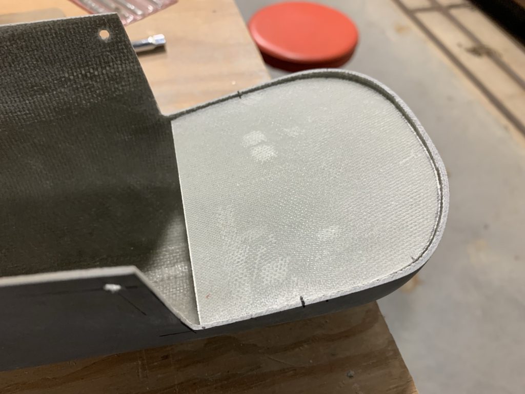
That’ll need another sanding tomorrow, then I think it’ll be time for an epoxy coat, or maybe I’ll locate and drill the wiring entry hole first, not quite sure the order I want to work in just yet. Here’s the sanded area before I filled the holes:

With nothing else to do in fiberglass-land, I decided to finally tackle trimming the control sticks and working installation details for the stick grips. The sticks are provided longer than needed, to accommodate various grip types; the Tosten MS grips I’m adding are pretty long, so quite a bit of trimming is required. First up I worked on the pilot stick; I marked where it interfered with the bottom of the panel, measured the height of the grip, and used that to mark my first trim line.

The fun part here is that in order to install the grip for a fit test, the wiring pigtail use be dealt with, which meant I also had to drill a hole for the pigtail to exit through; I put this on the front of the stick, just above the pivot point. Then there was the fun of fishing the pigtail down and out the hole, and finally I could see how it fit. Somehow, despite measuring carefully and adding an extra inch for clearance, I still ended up with the whole assembly a bit too long; here it’s contacting the bottom of the panel:

So I got to pull it off, fish the pigtail back out, trim again, and repeat the fishing maneuver. But then it cleared the panel, yay! (side note: look at that pollen on the panel displays…I should start covering this thing when I’m not working it…)

I still wasn’t quite sure about the length, though – from reaching over the cockpit rail, it seems there was enough room to move the stick under the panel even with my thumb on the hat switch, but I kind of felt like the best thing to do here was to actually sit in the seat and try it out. So I put the seat floors in place and the seats, starting with just the back. The rear stick needs to be trimmed as well, but here the interference concern is with the backrest for the front seat. First I climbed in the back seat, and ensured that that stick had good travel all around, and didn’t interfere with the seat bottom. Next I used a yardstick to simulate the location of the front backrest, and made a mark for the desired trim line, then reproached the process of subtracting the height of the grip.

One thing I’m read before was that the rear stick ends up being kind of absurdly short, and it definitely seemed that way once I got to trimming:

It looked even more absurd once I’d finished the trim:

At least in this case, the length ended up being just right, so I didn’t have to iterate on the trims.

Of course, this also meant I had to drill another passthrough hole for the pigtail. One important note here: this hole is kind of sizable, and there is a concern here about weakening the stick itself. In reality, I shouldn’t ever be putting the kinds of loads on this stick where it might matter, but this still calls for some special treatment. I wanted the insides of these holes to be as smooth as possible, with no stress risers that might allow a crack to start. So I rolled up some emery cloth, chucked it in the drill, and used that to really work on those holes:

Finally, I got around to trying out the front seat with the stick in place. Turns out doing this was a good idea; holding the stick naturally in this position, if I put my thumb on the hat switch, it hit the bottom of the panel. I probably could have worked around it in the air, but in the end it seemed better to trim just a little bit more. But with that done, I could finally get a decent grip and clear the panel:

The final bit for both sticks was drilling a hole near the top for the set screw that holds the grip in place. The pilot stick needed a bit of touch up paint where some of the powder coat got damager, but the rear stick I was able to finish up, including adding the snap bushing where the pigtail exits.

Next step here will be to trim the pigtails – as you can see above, there’s a lot of excess length – and add the terminations for the pigtails as well as the harness in the plane. I’m also going to add a closeout panel around the rear stick instead of leaving that hole open; I think I’ll have a bulkhead d-sub connector there for the removable rear stick. I suppose I need to do that before I can finish up the wiring back here.

Hopefully I’ll be finishing up that rudder bottom soon, and I can keep working on closing out the remainder of the fuselage wiring.

Posted in Electrical, Empennage, Fiberglass | Hours Logged: 4.5

Tail light wire routing

So I had assorted other things going on today, but I did find an hour to get in a bit of shop time. I skim sanded the micro I added previously for pinhole filling, then got to looking at locating where I wanted the tail light wire to enter the new bulkhead. This involved a fair bit of head-scratching and staring off into space. Optimally, I’d place the hole in line with the rudder hinge point, so that it’d have no movement at all relative to the fuselage, but I didn’t want the wires possibly rubbing on the rudder hardware. In the end, I chose to put the hole on centerline, but as far forward as possible. This is only about an inch or so off the hinge line, so it still doesn’t move much with the rudder going stop-to-stop.

Here’s a look at the finished hole with the wire in place for checking clearances and such. When it’s done, that hole will have a snap bushing, but first I have to do all the fiberglass finish work on this piece:

One fun bit that came out of this tinkering: what I thought was a generous amount of wire from back when I built the harnesses is, in fact, just barely enough. I kind of wonder whether this will end up being too short once I add the conduit run I’m putting inside the fairing. Worst case, I can just extend the two wires…it just might make routing things through the conduit slightly more interesting:

Posted in Electrical, Empennage, Fiberglass | Hours Logged: 1

Rudder bottom finishing work

Another quick session. I did a bit of sanding on the rudder bottom edge where it was a bit wavy compared to the rudder skin profile. Next, I removed the bottom, gave it a good sanding (I made some epoxy spots while working on the bulkhead), and countersunk all the attach holes. Finally, it got a coat of System 3 epoxy to hopefully plug any remaining pinholes.

Next up, primer…and hopefully not any more filler…

Posted in Empennage, Fiberglass | Hours Logged: 1

More rudder bottom finishing

Nothing exciting to take photos of this time around. Last night I sanded down the previous night’s epoxy coat to get rid of some mild runs that developed, then shot my first coat of primer. This turned out fairly well – the bulkhead I added had no pinholes whatsoever, but I did find a few back in the tail light area. Additionally, there were some chips around a few of the rivet holes that needed some attention, so after letting the primer cure for a few hours, I mixed up a small batch of body filler and took care of the couple pinholes. For the countersink chip fixes, I put a little glob of filler in each one, then inserted an unused CS4-4 rivet that had been dipped in acetone; this roughly formed the filler to the countersink profile.

That primer coat also revealed – as they tend to do – a few more imperfections that needed cleaning up, so tonight was another sanding night. In addition to cleaning up the areas where I added filler, I also took care of a few lumpy spots, and then shot yet another coat of primer. At a glance, things are looking good, but there are just a couple more spots I want to give some attention to, and after that I think I can apply the final coat and call the finish done.

At that point I’ll just need to install the conduit for the wire routing, and this thing should be able to install.

Posted in Empennage, Fiberglass | Hours Logged: 1