I should just stop thinking that, on any particular day, I’m going to finally nail down this throttle stuff. You’d think I would have learned this lesson way back with the empennage, but apparently not.
With the linkage roughly laid out, I figured tonight I’d mark the throttle arms for the linkage connection holes, mark the linkage for shortening (it was still a little long), and finalize the necessary spacer to locate both throttle quadrants correctly. I started by pulling the linkage and shortening it, removing about 1/4” from each end. Then I drilled a little deeper in each and and re-tapped the holes so I could have proper thread depth for the rod ends.
Next, I pulled the rear throttle apart (for the 900th time or so). Going the rod end route here means that I need some extra clearance on the outboard side of the throttle, so I fabricated a 1/8” thick spacer and added it to the assembly. I also had to add washers to the pivot point, which ended up with me realizing that I’ll need yet more bolts from Spruce. I can get the stop nut started on the pivot point, but it doesn’t have sufficient engagement. It’s enough to hold everything together for now, but not acceptable as a long-term solution:

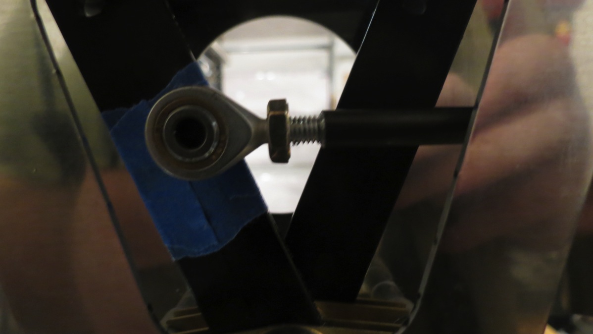
I also went ahead and drilled the new linkage connection point on the rear throttle before reassembling the entire thing. Here’s the new assembly:

Next, I removed the front throttle, disassembled it, and fabricated spacers of aluminum tube to move it outboard to the appropriate location. I also fabricated another 1/8” thick spacer to give the extra space needed for the rod end on the outboard side. The only thing left to do was to drill the linkage connection hole at the spot I’d marked (using the actual linkage in place). As a sanity check, I compared this mark to the hole in the rear throttle, and…uh-oh. The mark on the front throttle is a good 1/4” higher than the hole on the rear one. That’s not good – I want those to be the same distance from the pivot point so both throttles have identical travel. Having the point higher on the front throttle would mean that the front throttle would have reduced travel as compared to the rear one.
So now, the question is: how do I handle this? I’ve worked out a couple options so far:
The simplest option would be to simply drill the hole in the front throttle as marked. Based on my math, this would result in the front throttle travel being reduced by about 6.5° from the rear (43.44° vs 50°). I’m not sure this would make a huge difference, but the bigger question regards how the throttle rigging itself works. I don’t know if proper throttle rigging depends on the lever having the proper travel, or if this is easily adjustable using a linkage at the engine. I need to do some more research before I know whether or not this is a feasible option.
Another option would be to use the rear throttle arm as a template, drill the front arm to match, and enlarge the bulkhead passthrough holes as needed. By my calculations, I’d need to enlarge the center section bulkhead holes by roughly .2” downward. This would put the lower edge of each slot roughly vertically in line with a rivet hole shared with the bulkhead cap. I think this could be down without causing edge distance issues, but it would be close. This would probably be the most preferable option, assuming it causes no edge distance issues. I’ve only done rough measurements regarding edge distance, so I need to go measure precisely to determine the feasibility of this option.
The third option would be to drill the front arm as marked, and then red rill the rear throttle arm to match. This would allow me to basically leave the passthrough holes in the center section alone. The passthrough in the armrest bulkhead would need to be expanded, but I’m far more comfortable enlarging the hole there instead of the center section. The big downside here is that I’m 99% sure this can’t be done without replacing the throttle arm. I could probably just fabricate a new arm from 1/8” bar stock. The only other consideration would be finding somewhere local to black anodize the arm so it would match the rest of the quadrant.
Off the bat, #3 sounds the best to me. #2 might work, provided edge distance isn’t an issue. #1 seems like a bit of a hack that requires justification. I’ll have to think this over before deciding how to proceed.
In the meantime, here’s a photo of both throttles mounted with the linkage sitting in place:


