Firewall Forward

Mostly just FWF head-scratching

So yeah, not exactly a super productive evening. The sort of infinite recursion of dependencies is not playing well with my inherent tendency to overthink everything. I started out tonight thinking I’d hash out the exhaust hanger setup, but that didn’t go too well. There’s a whole debate around how best to secure the exhaust on these planes. Most people us a hanger setup that consists of two pieces of tubing, with the ends flattened and drilled for bolts, and joined together with a short piece of rubber tubing to provide some flexibility. Vetterman suggests securing one end to the exhaust and the other to an engine mount tube, but this seems to frequently lead to cracked hangers. So folks instead suggest securing the other end of the hanger to the engine itself, but the ones provided with the exhaust are too short for this.

That doesn’t even get into the other question of where on the exhaust pipes to secure the hangers. To figure this out on the #1 and 3 cylinders, I have to look at where to put the cabin heat muff. That probably needs to go as far forward as possible, but the next question is how the scat tubing for the heat muff inlet is routed. That got me pulling parts of the baffling out, which made me realize that’ll I need to rework a brace for the baffles due to both the case-top ignition coil mount and the injector tubes, as well as worrying about whether the case-top coil might hit the cowl.

This is a really long and drawn-out way to say that I’m not going to work not he exhaust right now. The baffling seems like the most pertinent thing to get going on, so I’m going to switch gears to that. In the meantime, I decided to switch to shop cleanup for the rest of the night. My big work table is a disaster, and there’s a bunch of crap piled on top of the finish kit crate. I want to be able to spread some stuff out on the table, and also pull the cowling halves out so I have them on hand for rough fitment checks.

Things sure aren’t spic-and-span as of yet, but I made good progress. I suppose I’ll keep going on that tomorrow, though I’ll have some electrical stuff coming in, so I might also fab up some more cables – there’s some stuff I can do there that’s not dependent on 40 other things…I think.

Posted in Firewall Forward | Hours Logged: .5

Baffles!

In my continuing quest to find something FWF to work on that didn’t have infinite dependencies, I drug out all the baffle components after work today. A nice touch here is that the instructions for the baffling come in the style of the newer kits – these combined instruction and drawing pages. So instead of constantly referring from a big page of text to a drawing, each page of the instructions has smaller, more focused drawings for reference. However, I kind of found myself uncomfortable with the very prescriptive nature of these instructions, and so I found myself skipping steps in short order.

The first step was just separating some angle/brace type pieces and doing some trimming on them. This was where I started skipping steps – in some cases the trimming of pieces was pretty obvious, in others it seemed less clear. I decided that I wanted to see these pieces in assembly with their neighbors to better understand the trimming, so I set them aside and moved on.

From there, we jumped to working on the left rear baffle components. This sent me in a new direction of uncertainty, though. The first bits were easy – just fitting and riveting a couple of reinforcements where the side baffle piece will be screwed into a cylinder head. The next bit involves fitting the oil cooler, though…and despite the drawings showing a pre-existing hole in the left rear baffle for this, my piece had no such hole. Some research indicated that it’s up to the builder to figure out this location. It also turns out that RV-8 builders quite frequently have clearance issues between the oil cooler and the cowling. Oh, and almost everyone adds extra reinforcement in this area, as it’s a common location for cracking from vibration.

The end result of all that is that I’m skipping the part where I fit the oil cooler for now. Presumably there’s plenty to do with the baffling before I get to that requirement…I guess we’ll see. In the meantime, as part of my goal to comprehend how the baffling comes together, I decided to temporarily fit most of the left-side baffling in place on the engine:

It’s nice to see that despite abundant uncertainty, this stuff all fits like a glove. Unfortunately, I wasn’t so lucky with the right baffling, which I tried stuffing in place as well. The right rear piece doesn’t seem to be shaped properly to fit against the engine, so it looks like I’ll have to do some strategic trimming there.

Basically, tonight once again involved a nontrivial amount of head-scratching, but I think I’m starting to wrap my brain around how all this stuff fits together. Hopefully I can at least make some good progress in getting this stuff together, even if I have to keep deferring things.

Posted in Firewall Forward | Hours Logged: 1

Chafe-proof firewall penetration

We were out and about tonight, so only limited time to do shop stuff, but my shipment from McMaster came in and I couldn’t resist having a go at my penetration solution. I ended up ordering slightly different tubing than what I originally expected to line this. At first I was looking at some nylon 6/6 tubing that was only 1/32” thick, but the minimum length was 5’. Instead, after some poking around, I realized that double that wall thickness would still give me a larger OD than the snap bushing I was using previously. So instead I ended up ordering some 3/4” OD, 1/16” wall thickness Delrin tubing – and I only had to order a foot, In addition to cutting down on wastage, this also reducing the shipping cost a lot.

The fun thing here is that the stainless penetration is a little less than 3/4” OD, not including the bit of taper on the forward end. So I needed to turn down the Delrin to get the press fit I wanted. Though I should say that “turning down” implies a lot more precision than what I did, which was to figure a way to chuck a short piece of tubing with the drill and then gradually sand down the OD while repeatedly checking the fit in the penetration. Once I had the fit I wanted, I cut off excess tubing length on the backside, carefully sanded and rounded both ends of the Delrin, and finally pressed it into the stainless tube.

The resulting piece is just long enough to protrude about 1/8” on both ends of the fitting:


And a test fit confirms that it’ll accommodate all the wires needed here with room to spare:

I do think I’m going to remove the insert and add some glue before reinserting it, just to be extremely sure that it’s not going to slide out. Probably overkill, but…that might as well be the name of this project at this point.

Posted in Firewall Forward | Hours Logged: .5

Baffles #2

Today was a day of lots of trial and error. As mentioned previously, the right rear baffle piece didn’t fit the engine as well as its left rear companion. Last night I put in a little bit of time to get ahead of this – I traced the baffle piece on cardboard and cut that out, to use as a starting point for the trimming. It only took a few iterations of trimming the cardboard to get a shape that seemed like a pretty good fit.

Today I traced that new shape on the baffle and did some trimming, before going for the first trial fit on the engine. Much closer to fitting, but not quite – I guess the flexibility of the cardboard hid some remaining fitment issues. The basic frame of reference I was using here was a screw attach hole for this piece, which is located near the top right engine mount. My goal was to get this piece to where I could install that screw and pull the baffle snug against the engine.

This ended up requiring something like five or six iterations…just lots of fitting, marking interference points, removing, trimming, deburring (this piece rubs on everything while weaseling it into place), then doing it all over again. But finally I had it in a state where I could actually mount it and mate it to the adjacent piece that attaches to the cylinder head.

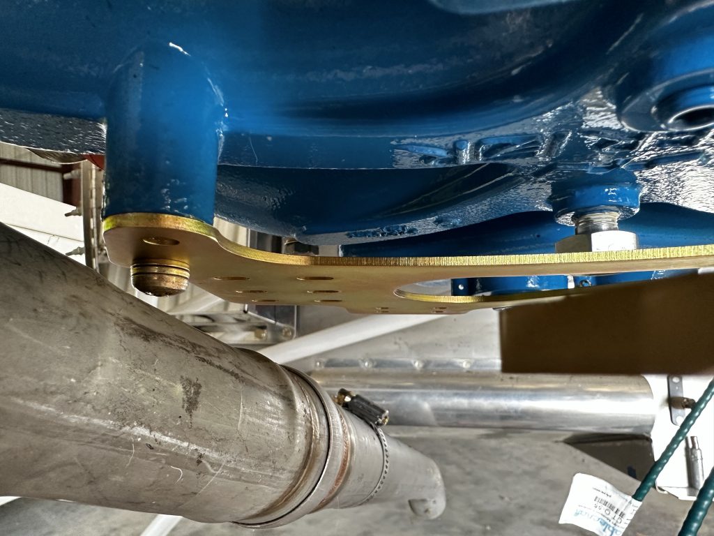
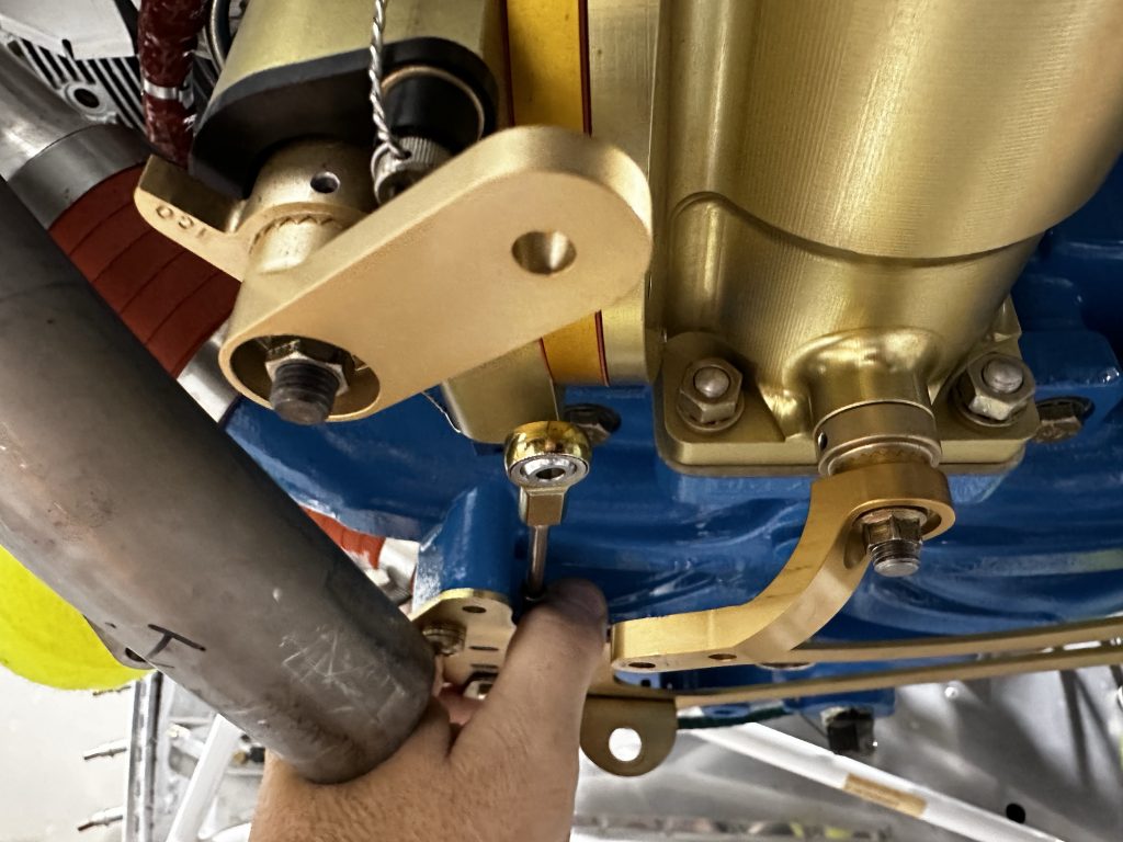
The next step was to evaluate how both of these pieces fit against the center brace. This is a little triangular piece that attaches to the top of the engine, and then to the baffling, to hold it in place. Getting this piece in required removing two case bolts, along with a mount for one of the injector lines. Notably, I won’t be actually using this brace, since I’ll be putting a coil pack in this same spot, but the brace is still useful for getting the baffle location right. And once I get that right, I can use that original brace to fab up an equivalent piece, which will end up being part of the coil pack mount.

Anyway, adding that brace to the mix set off another few rounds of trimming. In this case, the left rear piece did end up needing some work after all – it couldn’t quite scoot far enough aft to accommodate the brace. Fortunately, that only required maybe two iterations. The right rear piece took quite a bit more before I was finally satisfied with its positioning.

I figured the smart direction to go from here was to look at the coil pack mount. I still have some concerns about interference with the pack and the upper cowl, so the first step was just holding the pack roughly in place to see how it looked. The good news was that the rear edge sits well below the baffling, which implies that that area should be fine. However, it’s not clear exactly how the cowl will slope down from the baffle area to the front of the engine. I did a rough check by laying a yardstick from the baffle to the flywheel, which seemed encouraging but not particularly satisfying.

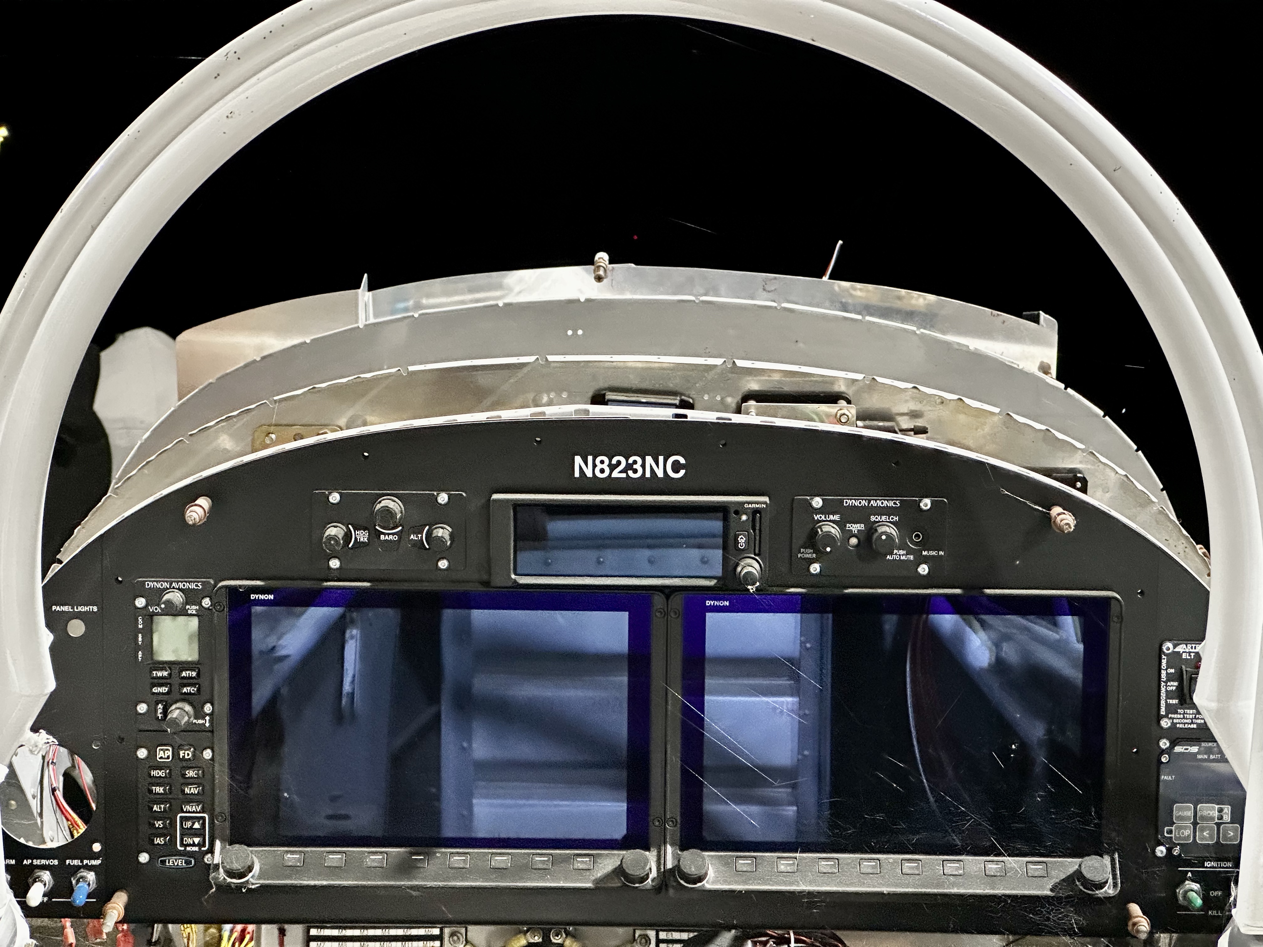
So I decided this was as good a time as any to drag the cowling halves out of their crate and see what things looked like. Hey, it’d have the side benefit of briefly making this thing look even more airplane-y, right?

Unfortunately, this ended up sort of derailing the day, as it turned out. After extracting the cowl halves, I tried draping the upper cowl over everything. I knew it probably wasn’t going to fit perfectly, but I just wanted some sort of rough idea. Thing was, it just wouldn’t drape properly. It would either rest on the flywheel and the baffles, or the baffles and the firewall flange. The baffles themselves seemed way too high. A closer look revealed that it was mostly the outboard corners of those baffles.

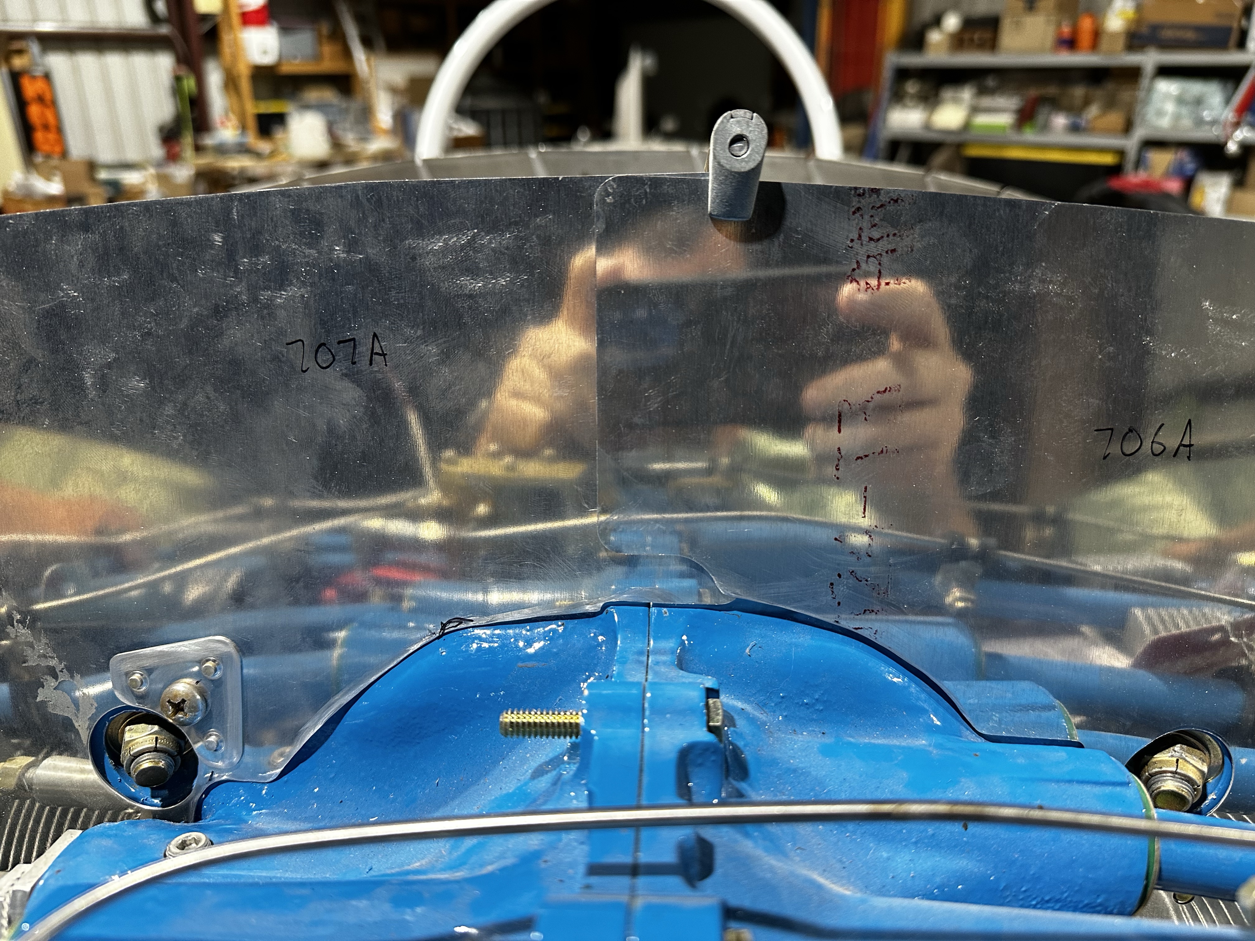
At this point I took a step back and observed, for the first time, just how different the top contour of the baffles were compared to the firewall:

I also had a moment of clarity regarding the part numbers for these pieces. Everything had been either CB-7xx or CB-10xx. It’s worth noting that for kit part numbers, the first number generally designates the model – so -8 parts might be W-8xx or F-8xx or whatever. The logical conclusion was that these were parts originally specified for an RV-7 or RV-10. Uh, did I get the wrong parts?

Digging up the FWF packing list showed that yes, I really did receive a kit for an RV-8. So I went looking for RV-8 build logs, and found one with lots of good baffle pictures, which…looked just like mine. And the builder made note of how they’d need substantial trimming to fit an -8. Well hey, there’s something I didn’t realize before…

Further digging showed that while Van’s does have an -8-specific baffle kit for an angle-valve IO-360, there’s no such thing for a parallel-valve like mine. Well, there’s something fun to look forward to.

The other thing I learned from this research is that I’m jumping the gun on some work again. I was thinking that the baffles needed to be in place before the cowl was fitted, but it seems that it’s the other way around. Which probably means that I’ll be switching gears to that task pretty soon. In the meantime I’m going to continue working on the baffles, since I already have all the parts pulled out and spread on the work table – I guess I’ll get as much done as I can right now, then put it all aside to work on the cowl instead.

Boy howdy, there’s sure a lot of jumping around and false starting on this FWF stuff.

Posted in Firewall Forward | Hours Logged: 4.5

Cabin heat feed, ignition mount start

This is another two-day post; yesterday I was mostly busy working on Helio stuff, but I did get some time in the shop in the evening. The first thing I was working on was making the hole in the right rear baffle that will feed air to the exhaust heat muff, and thence into the cabin. I used the provided flange part to outline the required hole, and marked the center. Unfortunately, because of the bends in the baffle here, I couldn’t use my trusty hole cutter, but I was able to use the largest of my knockout punch set to make a starting hole that was only about 1/8” undersize. Then I just opened the hole up to my outline with a Dremel cutting bit.

Next I clamped the flange in place and drilled the four rivet holes, followed by some fine-tuning of the hole. At this point I was ready to rivet the piece in place…or so I thought. There’s a provide piece of metal screen that’s to be trapped between the flange and the baffle, I guess to prevent debris (like insects) from entering the cabin in-flight. The plans call for tank sealant to be used in between the flange and baffle, I assume to keep the joint well-sealed. I was planning on using some good old RTV, but…turns out I don’t have any. I think now I remember that the last time I needed RTV, I had to poke a hole in the side of my tube because it was so dried up.

So I just set this aside for now, and moved on to starting on the real fun fabrication work: the case top mount for the ignition coil pack. I busted out the angle I bought for this purpose, did a bunch of measuring, marking, and laying out, and got to work. After drilling the two bolt holes, I outlined the material I needed to remove from the vertical flange. This is necessary both to ensure the mount fits well against the case, as well as to provide an aperture for the fuel injector line to go through. After all, the whole reason for this custom mount is to work around that line.

After all that layout work was the usual dance of drilling holes, rough cutting with the bandsaw, refining the shape with a cutter in the Dremel, and straightening things up with the file. Then it was time for the big event: a test fit on the engine. It lines up nicely and provides good space underneath for the injector line, so it looks like it’ll achieve its purpose:


Of course this is only one of the two mount pieces; I’ll need to make essentially a mirror image that will go on the other side of the case. There will also be more trimming to be done – these pieces are intentionally oversize, and once I get the location of the coil pack right, I should be able to remove a good bit more material. I’ve also got to think of how I’ll adapt a brace on the backside of this piece for the rear baffles.

But hey, things are going well so far. I’m thinking that from here, I’ll finish the coil mount, get the coil in place, then set the baffles aside and start working on fitting the cowl. That way I’ll get my look at whether the cowl properly clears the coil pack – it’s still possible I might have to relocate the coil elsewhere, though I sure hope not.

Posted in Firewall Forward | Hours Logged: 2.5

More coil mount work, getting ready for cowl fitting

Tonight I picked up where I left off with the coil pack mount. Since the first piece from last night fit up nicely, I used it as a pattern for making its mirror-image mate. Drilling the two bolts holes and roughing out the cuts went pretty quickly, but it took a little more work than that. Turns out the case casting is slightly different on the left side, and I needed to remove a little more material to get it to fit nice and flush on the case.

Once I got both pieces bolted in place, it was time to set the coil pack on top and evaluate the fit. One concern I had after last night was whether these two pieces of angle would actually provide a large enough mount pad for the coil pack. After the test fit, I think this is going to be fine, though there’s not a lot of extra space. I could make this a little better by adding some washers or spacers between the brackets and the case, but doing that would make this a lot more annoying to install or remove. I’ll have to evaluate the actual edge distance on these bolts to make a decision here.

The other thing to evaluate here is the clearance between the coil pack and the cowl. In an attempt to get a first approximation of this, I once again draped the cowl over the top of the engine and firewall. I found that the cowl would rest on the coil before it contacted the flywheel, which isn’t necessarily a bad thing. After all, the cowling isn’t supposed to contact the flywheel, but the unanswered question here was what the right position for the cowl nose ought to be. Both the vertical and longitudinal positions here can make a good bit of difference in clearance with the coil pack.

So I decided that this was a good time to do some of the prep work for fitting the cowl. The nose of the cowl gets its position set relative to the prop spinner backplate, so that backplate needs to be in place for this. In the case of a CS prop like what I have, the backplate attaches to the prop itself, which means that I need the prop in place to fit the cowl. So I got to work breaking out the prop and spinner, installing the backplate, and finally actually hanging the prop.

Installing the prop is a bit of a slog, though that slog is balanced out by, well, by the fact that I’m installing the prop, which is sort of a cool milestone. The thing is that the six prop bolts are captive inside the prop hub, and the arrangement means that each bolt can be turned about one flat at a time with a wrench. Additionally, the bolts need to be tightened gradually and equally, to pull the prop squarely onto the crank flange. What this means is that I did a lot of walking from one side of the prop to the other and back. All told I think I spent 40 minutes tightening those bolts.

I haven’t done a real recheck of clearance with the coil – I also need to rig up something at the front of the engine to support the cowl nose at the proper height – but I did lay it back on top just to help get some “hey, it looks even more like an airplane” photos:

Fun fact: you may notice some mud dauber nests on the prop blades. At least those are easy to clean off, right now they’re making my nice carbon fiber blades look not as good as they’re supposed to.

So there we are. I need to get some hardware to rig the from cowl support, and also install the forward top skin, but I’m in a decent spot to start thinking about laying out the first big trim cut on the upper cowl.

Posted in Cowl, Firewall Forward | Hours Logged: 2

Standby alternator install

So, in sort of an attempt to get some momentum going on this project, I’m pausing on the cowl stuff for a bit, just to get some more fun stuff done. This was somewhat enabled by receiving some parts that I’ve been waiting on for almost a year. Way back when I was trying to get all my accessories mounted before hanging the engine, I discovered that the 90° oil filter interferes with the B&C vacuum pad alternator I’d bought. So at the same time I was ordering a different oil adapter from B&C to work around my engine mount, I also ordered a drive extension kit from them. The extension kit was backordered, but that was OK…I wasn’t in any huge hurry, and worst case the airplane could fly just fine without the standby alt.

Of course, that backorder period was a good bit longer than expected, but it matched up fine with my work ethic (or lack thereof). In any case, last week I got an email from B&C that the parts were finally in, and they showed up here a couple days later. Finally, something relatively simple and fun to do!

The kit consists of a few different parts: first, a longer shear coupling that’s installed on the alternator spline drive, a spacer for the mount pad, and the most fun part: four longer mount studs. So Job #1, after removing the existing blanking plate, was to remove the old studs. In a pattern well-known to any DIY mechanic, the first three studs came off with relative ease, but the last one was a real bear, and required some torching to remove. Really fun trying to heat the stud without scorching anything else nearby…

After that, it went well…new studs went in easily with the provided stud installation tool, then I just had to stack everything together. There’s a gasket, then an adapter with a gear to the accessory drive inside and the splined socket outside, then another gasket, then the spacer, then another gasket, and finally the alternator.

That said, this isn’t 100% done yet. I unwisely used the same mount nuts for the stud removal, and a couple of them got rounded while working on that one stubborn stud. I went ahead and used them to mount the alternator, but I’m going to replace them with new nuts at some point. Oh, and did I mention that I just placed an Aircraft Spruce order today? No matter how hard I try to combine Spruce orders to save on shipping, it seems my efforts are doomed to failure…

Anyway, here’s a shiny new alternator on my shiny new engine:

Posted in Firewall Forward | Hours Logged: 1.5

Injection servo mount fix

This was another of my FWF tasks that I’ve been putting off for a while. I discovered some time ago that as provided, the FM150 fuel injection servo interfered with the bottom cowl. I also determined that if I removed the 1/2” spacer between the sump and the servo, the clearance issue went away. Some research indicated that the only reason that spacer is there is because Superior provides really long studs with their cold air sump. That is, it’s just there to accommodate the mount hardware.

Well, as part of a Spruce order I put together last week, I figured out what studs I needed here and got those added to the order. That just left the fun of removing the old ones and installing the new ones. Removing these was a lot more fun than the alternator ones from a few days ago – these were really tight, to the point that my first attempt to remove one using two nuts and some heat failed miserably

I was on the brink of ordering a special stud removal tool, but I decided to give it one more try, this time being more generous with the heat. Turns out that about a 30-second blast with a Mapp gas torch puts enough heat in to break the stud loose, so I was back in business. Most of the fun came from figuring out how to orient the torch to heat the stud without destroying anything else in the area, like the rubber intake boots visible in this photo of the stud-less sump:

This led to a surprisingly long and tortuous discovery session. You see, at a glance, it looked like the studs I ordered were too short to fully engage the sump while also providing enough length for the servo and the mount nuts. I actually came pretty close to ordering another set of studs that were 1/4” longer…oh, and those studs were $18 each.

What made this fun was that I didn’t want to just install a new stud without knowing it was right – so I ended up measuring, re-measuring, reading up on proper thread engagement, and so on. Eventually I decided that these studs would work, to the point that I was confident installing one. But it was also critical that I thread the studs in to a very specific depth, so I ended up using a washer stack on each stud to give me a nice precise stopping point during installation.

After all that worrying, the first stud I installed gave me the chance to verify I had good engagement with the servo, and then the other three went in in about ten minutes. Finally, I got the servo back in place, torqued all the mount nuts, and reinstalled the fuel lines. After being temporarily mounted with a lot of stacked washers for a while, this servo is finally back in place for real:

I guess I can’t really put off cowl trimming any more now. That’s going to be a lot of fun, seeing as how it looks like we’re going to have near-triple-digit high temperatures for the foreseeable future. Sweat and fiberglass dust are not a very enjoyable combination…

Posted in Firewall Forward | Hours Logged: 1

Injector line reroute

So, I’m pretty happy tonight – I worked out a problem that’s been nagging at me for a while. Previously I’ve mentioned how one of the injector lines interfered with the case top mount for the SDS coil pack, and a while back I took a crack at making a custom mount out of some angle. While the mount itself turned out OK, I discovered while fitting the top cowl that the mount was too tall, causing the coil pack to contact the cowl.

I’ve been rolling around ways to address this for a while. I’d initially thought about making a new custom mount that sat lower, but since the whole idea of that mount was to let the injector line pass below it, there wasn’t really any room to make much of a difference. This week I got back to brainstorming how to handle this, and eventually I decided I only had two real options: either relocate the injector line, or put the coil pack somewhere else. Mocking the coil pack up on the other magneto pad wasn’t encouraging; between the oil pressure sender line and the CS prop oil line, it’s pretty tight back there.

So I went on a research journey on the topic of these injector lines, starting with the intent to buy the materials needed to make a new line. It turns out that these lines can be bought prefabricated, in whatever length you need, and they’re hand-bent to the required routing. That indicated to me that simply massaging the routing of the line I had was a reasonable way to approach this, so I started down that road.

The good news is that this line had enough slack in it to allow for the rerouting I had in mind. A little more bend at the flow divider allowed the line to cross the case a couple inches further forward, in front of the SDS case top mount. I was able to reuse the previous retention mount on the side of the coil mount, thus securing the line just past the case split. Further over, the adel clamps already in place on the pushrod tube still worked just fine.

With the coil pack loosely in place on the mount, we can see the routing. The main area of concern while I was doing this was the spot in this photo – the clearance between that bend and the coil pack mount. I was able to get about an inch of clearance without violating the minimum bend radius specs for this line:

From the other side, we can see how the nice billet mount was reused to secure the line:

This was very satisfying, but it left one more question: supporting the rear baffle. Normally, there’s a brace that goes from the case top to the baffle, but the coil pack mount precludes using that. I’d been planning on figuring some way to brace from my custom mount to the baffle, but hadn’t really worked it out. Since I had the coil pack mocked up in place, I decided to put in the baffles to see how things looked. It turns out that the baffles are close enough to the coil pack that this will be an easy problem to solve – I can just use a small piece of angle to tie the baffle into this mount screw on the coil pack.

I still need to go back and permanently mount all this stuff – for example, the coil pack mount bolts are only hand-tight right now. They’ll need lock washers and torquing as well. I suppose I can go ahead and bolt the coil pack itself in place as well; that way I can double-check the cowl clearance next time I put the top cowl on.

I’m somewhat tempted to quit working on cowl fitting for the time being, and get back to general FWF cable routing and so forth. The whole reason I started on the cowl was to allow working on the baffles, which I guess I’ll still need to resume before I can finish off all the FWF stuff. I think I’m just trying to avoid that whole fiberglass + sweat situation, but there’s not going to be any way around that for probably another four months or so.

Posted in Firewall Forward | Hours Logged: 1

Control cable planning

Today, in my continuing effort to avoid sanding fiberglass, I decided to take a stab at routing and so forth for the engine control cables. The idea wasn’t to end up with them final-installed with the throttle quadrant in place, but i did want to verify that the cables Van’s had supplied with my FWF kit would work with my nonstandard fuel injection and sump setup.

The cables are identical in design, but different lengths – there are two 55” cables and one 60” one. Despite looking all through my plans, construction manual, and other materials, I couldn’t find anything specifying which cable was for what. But it’s not really hard to figure out – for example, the prop governor is mounted on the back of the engine, close to the firewall, so clearly that’s where one of the shorter cables should be used. And the mixture arm is further forward and right than the throttle, so logically it should require a longer cable than the throttle.

In order to test all this, I routed the cables through the firewall and the left gear tower, and simply secured them to back side of the gear tower. This places them close enough to where they’ll eventually be affixed to the quadrant to allow for fitting – there might be an inch or so of variance, but that shouldn’t be enough to make the fit-up invalid.

Meanwhile, I got the required cable bracket attached to the prop governor, and routed one of the 55” cables over to it and temporarily added the nuts to secure the cable. This application, as expected, worked just fine. Honestly the 55” cable is a bit long, and I briefly considered replacing it with a short one, but considering this is the cable Van’s specs here, I don’t think there’s any reason to second-guess things. The extra length my be a good thing to help keep the bend radii in the cable larger.

Well, that was easy…time to start looking at the throttle and mixture cables. Before doing that, I needed to test-fit the cable bracket I bought from Showplanes. This piece is CNC cut to mount to the Superior cold air sump, and provides several sets of holed for attaching cable brackets. I still need to order the right bolts to attach this, so for now I’m just using some 1/4-20 screws from the cylinder baffles to secure the bracket for test-fitting.

The example photos on the Showplanes site show the cables routing above the bracket – that is, between it and the sump – but that seems way too cramped to me. It’s definitely too cramped to use the cable brackets that I also got from Showplanes. I thought about maybe using washers to space the bracket down a bit for more space, but the real critical concern here is clearance with the exhaust. The #1 pipe is really close here, to the point that even the attach bolt is going to be a tight squeeze. Moving this entire assembly down by even 1/8” just isn’t going to happen:

That got me to trying the throttle cable routing; this uses the rightmost set of holes in the above photo. For this spot, putting the cable bracket on the bottom of the mount bracket works fine. and it lines up nicely with the throttle arm. The only downside is that the 55” cable is too short – but the 60” cable works perfectly. I was able to fully mock this up, with the rod end on the cable, a bolt through the throttle arm, and of course I had to go reach in the cockpit, move the end of the cable, and make the throttle arm move.

So the next question was – could I also use the 60” cable for the mixture. Since I only had one 60” cable on hand, that meant I had to detach the throttle stuff and try routing that same cable to the mixture arm. But before anything, there was the issue of the exhaust clearance. The mixture bracket is further left and forward, and none of the mount hole options clear the exhaust.

To make a long story short, after a lot of thinking and trying a lot of different stuff, I hit on the idea of mounting the cable bracket from below the mount plate, but with the actual bracket posting up. This allows the cable to route between the plate and sump, and to sit low enough to clear the sump. Doing it this way did require me to grind some material off the cable bracket, and also to open up the holes on the mount plate, but in the end I got a setup that allowed the cable to properly align with the mixture arm:

The only problem, as seen above, is that the cable doesn’t reach the mixture arm. A longer cable also won’t help here, because that would require the cable bracket o be further forward, which isn’t possible with this positioning. Instead, I’m going to add a 3” extension to the end of the cable to get the reach I need…which is something else to throw on my Aircraft Spruce order list.

Posted in Firewall Forward | Hours Logged: 5