After an overnight stay in Houston for the FlightAware holiday party, we got back home early this afternoon, and I found a few hours to get a spot of work done. I decided to go ahead and attack stringing the rudder cables, even though I won’t have a rudder to connect them to until my rudder stop comes off backorder and ships (hopefully this week).
Stringing the cables is a fairly straightforward procedure; you feed them in from the rear and just slowly move them forwards. There are two sections of protective plastic tubing around the cables; a short section at the rear avoids chafing where the cables pass through the aft side skins, and a longer section further forward protects where the cables run in close proximity to the rear-seat footwells.
The cables end up passing through essentially every bulkhead from rear to front, and as the cable is threaded through each passthrough, a snap bushing is slid over the cable end and popped into place. Things get interesting, though, when you make it up to the seat floor area. This is where we need to rig that long plastic tube in the footwell area. Here, the cable passthrough is a small detachable piece on each side, which is attached to a seat floor angle with a screw. I’d already riveted the nutplates here, so it was time to do the snap bushing rigging.
We want the plastic tube to be fixed in place, so it gets secured to the snap bushing and the cable guide at its aft end. This is just a matter of cutting a small hole in the tubing, forward of the snap bushing, and threading a zip tie through that hole and the end of the tubing, to secure it to the support.
Here’s the support threaded into place:

And here it is with the zip tie installed. Note that I chose bright orange for really no reason whatsoever:

With that done, I returned to the rudder pedal assembly that I was working on last Friday. I’d mostly reassembled this, save for reattaching the brake pedals, so I got those back in place. I still haven’t installed the cotter pins on these pivot pieces – I thought about doing that today, but decided there’s still no reason to finalize the assembly yet. Then I got the pedals installed on the forward floor.
This was a bit interesting, and where my delaying of riveting the forward bottom skins caught up with me a bit. The pedals attach to two nutplates through the firewall on the forward end, and two nutplates through the floor at the aft end. Well, those aft nutplates aren’t there yet, since they’re riveted as part of the forward lower skin procedure. For now, I just put two bolts through to locate the pedals there, though it occurs to me I can cleco two nutplates in place, and will need to do so to actually test this stuff out. That’ll be another day, though.
From there, I wasn’t quite sure what to do, so I decided it was time to mock up the cockpit a bit more and start evaluating my panel/control layout. Of particular concern was the location I’d chosen for the SDS CPI2 electronic ignition system’s controller. In my mockup, it fits fine on the left panel wing, but in the cockpit, there’s a canopy rail that seemed like it might make access interesting. Also, the forward top skin/glareshield figured in here too, so I dragged that out and clecoed it into place. I also stuck in the throttle quadrant for maximum realism.
It’s really looking airplane-y now:
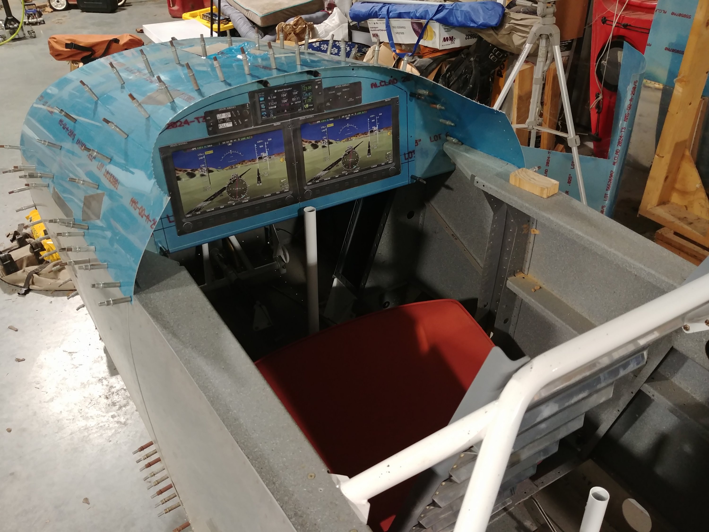
And then I hopped in and spent a fair amount of time just sort of chair-flying:

And lest anyone thing this was just a chance for me to sit in there and make airplane noises, I was attempting to really evaluate how the cockpit flow would work out, and I’m actually considering making some changes. For one thing, the paper cutouts I have now aren’t quite right. The displays are older Skyview Touch units, whereas I’ll be using newer HDX units. They’re essentially identical in size, though, so this doesn’t really affect the mockup hugely. More notable is that the TSO’d GPS I have is a GTN650; I think I made these before Garmin announced the much more budget-friendly GPS175 earlier this year. The GPS175 has a bit less screen height that the 650, so what I have here is a bit off.
The big remaining question is how I want to lay out my various switches. I’ve already decided that lighting and other similar stuff will go down on the right-side console, and common in-flight switches (that won’t be on the stick grip) I intend to put on the left wing panel, just above the throttle – but that still leaves me with a handful of switches to manage the electrical system. Most of these I’ll only be touching at startup/shutdown, but some will also be emergency-procedure items, ie handling in-flight electrical failures. So there’s the question of location there – I don’t want them in an annoying place no matter what, but I’m not sure how close at hand they need to be. And really, after sitting in here, the panel is so small that I’m not even sure I need to be careful about location – nothing on the panel is going to be hard to reach.
Anyway, I’m leaning towards something like this:

Its not quite as OCD symmetrical as previous designs, but I don’t think it looks horribly unbalanced or anything, and I like how it moves some of the controls. Shifting the displays right a bit means that the left display (PFD) is a little closer to centerline. I may even run that screen normally split between the flight controls and engine instruments, and have the left one be all map all the time. This also moves the com radio down closer to where my hands will be, and the power distribution switches all end up where they’re easily reachable by my “free” left hand.
One thing that may be smarter would be to swap the intercom and autopilot panels. I like having the intercom panel by the radio, since they’re sort of associated, but the intercom isn’t something I’ll be messing with frequently. The AP panel, though, is way more likely to be used in-flight. Of course, functions for both the AP panel and radio will also be able to be accessed through the touch screens.
Anyway, I could go on about this all night, but I should probably sleep at some point. So I’ll just stop here…