Hall sensor install

Seems like it’s been tough to find shop time recently…we’ve got a lot of stuff going on weeknights, and even weekends get busy sometimes. I did get some time in Sunday afternoon, though, which is where most of what I’m writing about here happened. It was just this afternoon that I finished up this bit of work and decided it was worth writing about.

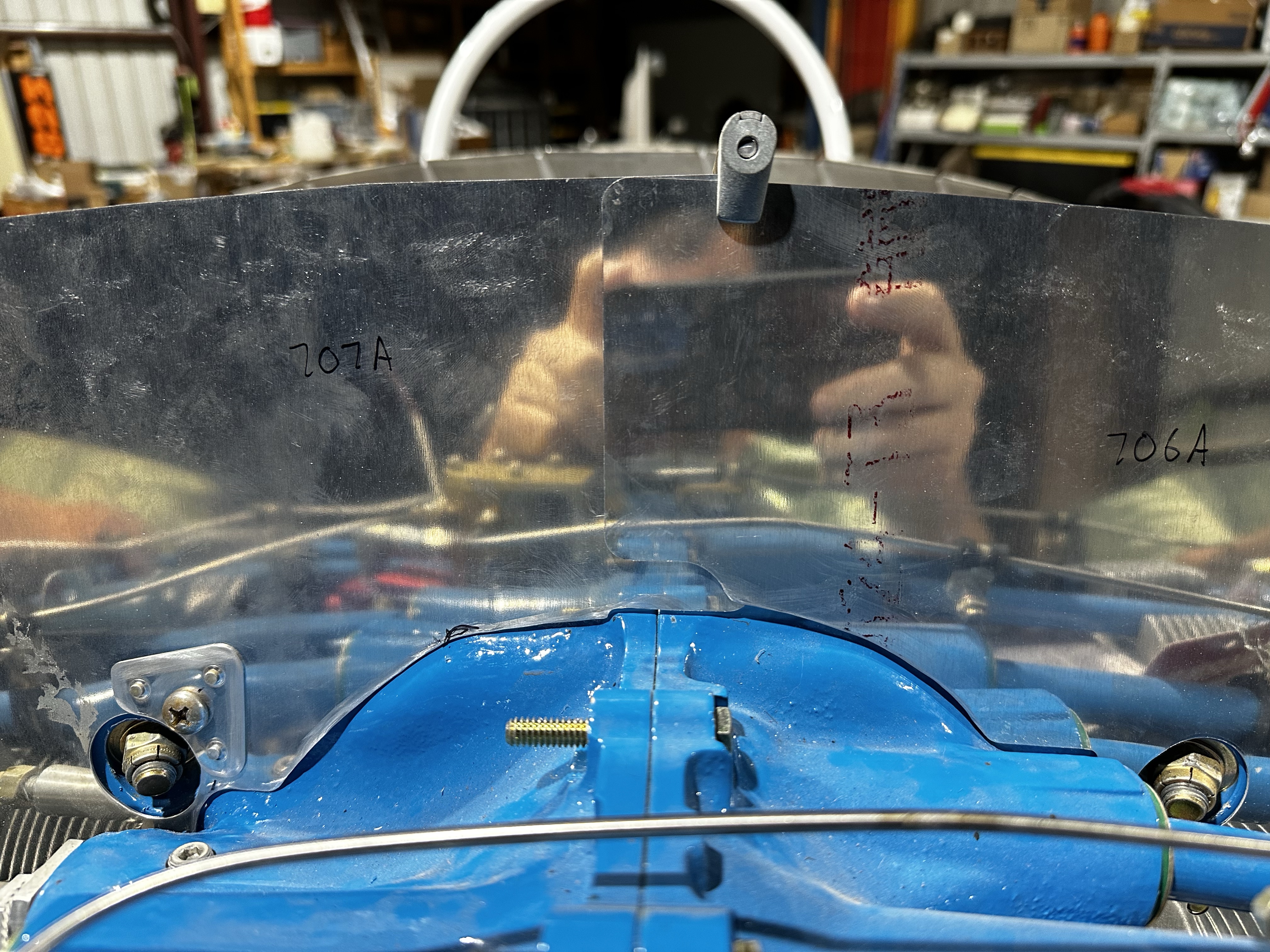
As mentioned previously (I think), I wanted to make a wire guard for the SDS hall sensor. Most folks seem to add some protection here – if the alternator belt fails, it’d be A Bad Thing for it to take out this sensor wiring as well. I followed the lead of other folks here, using some aluminum angle to fabricate the guard. The sensor mount includes a few different 3/16 threaded holes for mounting guards, which I took advantage of. Most of the work here was just laying out the cutout for the wires to pass through, then fine-tuning it for proper fit. Lots of drilling, dremel-ing, and filing.

Also, another fun part of this work – remember all those repeated tries the other day to get the safety wiring job on the sensor mount to my satisfaction? It was pretty clear that the best way to fit this guard was with the sensor mount removed, so I cut off that safety wire work, which made me a tiny bit sad.

Anyway, here’s a look at the backside of the finished guard, showing the two mount bolts. This was just a temporary assembly – for final assembly, both these bolts got lock washers and torque seal for good measure.

Next, a look at the reinstalled mount with the guard and sensor installed:

The next question is where/how to route the sensor wires. I’m thinking about first securing them to the prop oil line (seen in the left of the photo above), but the question is whether they should then go above or below the cylinders. I’m pretty sure above is the right answer, but like all things FWF, it’s something else to go read about.

In other good news, I got my Spruce order in, which includes some raw materials I needed, plus the hardware with which to finally mount my mag-pad coil pack, plus the blanking plate for the other mag pad. I’ve also got my new fuel hoses from AS Specialty coming in Thursday, so I should be able to finalize the fuel line routing this weekend.

I’m thinking I’m pretty close to wanting to hang the engine on the fuselage again, mainly so I can finalize planning the battery box mount and other firewall stuff. I figure I’ll remove the engine one more time to have room to work on that stuff, and then I’ll hang it for good, and start thinking about routing wires and so forth through the firewall…

Posted in Firewall Forward | Hours Logged: 3

Fuel system planning

OK, so today I completely changed gears and didn’t do any more ignition-related work – instead I got to playing around with fuel-related stuff. Ever since I received the engine, I’ve been bothered by the routing of the supply line to the throttle body. This line goes from the mechanical pump at the back left of the engine, and just sort of hangs underneath the sump on its way forward. That’s not great because…that’s where the exhaust will be.

This was one thing I was interested in while looking at RVs at Oshkosh. One I saw with the cowl off had a pretty obvious solution – just route the line around one side of the engine, above the intake runners. But that plane had a different fuel injection setup from mine, so it still required some thinking on my part. That setup had the throttle body inlet on the middle left side, whereas mine is low on the right side. That’d make for some interesting routing to get the line up above the intake runners.

However, while looking over documentation on my injection setup, I found an example photo that showed a really simple solution. The throttle body doesn’t have to be oriented any particular way, and in this example photo it was rotated 90° from my orientation. This moves the fuel inlet to be high on the right side. A quick test run of this setup showed that it makes for great positioning of the inlet – the hose is at the perfect level to route around the right side above the runners:

An additional benefit is that after moving the throttle arm to the opposite side of the body, both it and the mixture arm are in a great position to mate with the control cables, which can come right underneath the oil sump:

And at the back of the engine, the hose has plenty of room, as well as plenty of spots to secure it along the way:

The only thing that was going to be odd about this was connecting the hose to the mechanical pump. This came with 45° fittings on both the inlet and outlet side, which weren’t ideal for my new arrangement. But I figured that’d be easy to solve, I could just find the right 90° replacement fitting. Fortunately, before I added that to my shopping list, I went to go looking through the FWF kit to see what hoses were in there – mainly I was thinking of the feed hose from the throttle body to the flow divider on top of the engine. Turns out there are already two of the 90° fittings I need in there. I should probably look in that kit more often, this surely isn’t the last challenge I’ll try to puzzle out on my own unnecessarily.

The one thing I haven’t decided yet is whether I want to get a new supply hose. The one I have is the right length, but would need another 90° adapter on the fuel pump end. This would be easy enough to get, but I’m kind of wondering if it would be better to get a new hose with 90° fittings on each end. This way, I could eliminate two adapters, both of which are additional potential leak points. The downside of this approach is that a new hose is…let’s just say quite a bit more expensive than an adapter. Then again, I could probably resell the hose I have now and recoup some money.

Anyway, that’s where I’m at today. I’m holding off on my Spruce order for the time being; I want to look at my firewall component mounting and see if I may need some additional hardware for those items. It’d be nice to get as much stuff on hand as possible, so I can roll with the momentum I’m feeling right now. Mounting everything on the firewall means I can be free to re-hang the engine when I’m ready, which will in turn allow me to start working on really fun stuff like control cables, engine sensor wiring, and so on.

Posted in Firewall Forward | Hours Logged: 2

Ignition stuff

Today was mostly one of those sort of head-scratching days. I did some research last night about mounting the SDS coil packs, mainly wondering if there was a way around using the case top mount even with the fuel injection lines. Oddly enough, I never had the obvious thought of just fabricating my own mount, but I ran across someone who’d done just that. Pretty simple too, just need some angle of the right size to make the mounts and raise the coil pack a bit for the lines to pass underneath. I just don’t have the right size angle on hand, so that’s something I’ll need to order.

Having decided to stick with the case top mount simplifies some stuff for me, though. I never got around to ordering another mag mount from SDS, and now I don’t need it. It does add a new decision, though – which mag mount should I use for the one coil pack I am using? I did some test fitting of the coil and eventually decided that the left side of the engine was better – the right offers lots more obstacles thanks to the prop governor below and the standby alternator above the mag mount.

It would have been nice to go ahead and mount that coil pack, as well as the blanking plate on the other side, but…I don’t have the right nuts on hand. More stuff for the to-order list. I ended up just pausing and focusing on fleshing out a Spruce order. I know I’ll want some more adel clamps to use for FWF routing of stuff, plus I’ll just want a general stock of the metal lock nuts for FWF mounting. I suppose I’ll wait and see if I come up with anything else tomorrow before maybe placing the order on Monday.

So finally I moved to something I could actually do and not just plan – mounting the Hall sensor up on the nose of the engine. This requires loosening the two front case bolts and replacing the nuts with standoff nuts that the sensor can then bolt to. The sensor mount itself requires a bit of trial and error to get the proper air gap between the sensor and the inside of the flywheel – there are a few washers to move around to tune the spacing. Once I’d worked that out I torqued the bolts and…it was time for some safety wiring.

To make a long story short, it took me about four tries before I was satisfied with my work here. I haven’t done a ton of this, so I’m still kind of learning the ropes. And probably the second and third tries would have been serviceable, but…I guess I get a little perfectionist with this stuff. Here’s the final product on the sensor mount:

At this point, since I already had the wire stuff out and was in the mood, I went ahead and final torqued the alternator mount boss bolts and safety wired those as well:

I’ve still got a little work to do with the hall sensor mount – most folks fabricate a cable guard out of small angle to protect the sensor cable in case the alternator belt breaks. Seems like a good, cheap insurance idea, so I’ll be doing that tomorrow. Once that’s done I should be able to mount the sensor, and then I get the fun of drilling the flywheel for the trigger magnets.

Posted in Firewall Forward | Hours Logged: 3

New oil filter adapter

As the title indicates, tonight I worked on swapping in the new shorter oil filter adapter from B&C. This is half of the work needed to allow the standby alternator to be mounted, but it’s all I can do for now. The drive adapter is backordered with no estimated ship date, so I have no idea when I can expect it. I guess maybe I’ll see about mocking up the alternator for the purposes of firewall planning…

Anyway, not a lot to be said about the adapter swap – the hardest part was breaking the oil filter loose. I’m not sure who installed that thing but I’m pretty sure they exceeded the torque spec by quite a bit. I also had to move over the vernatherm (which regulates flow to the oil cooler) from the old unit, and I went ahead and installed the oil temperature sensor as well. These can be seen in this photo; the vernatherm is the large piece below the smaller sensor:

The one thing left to do here is to get this stuff safety wired. That might be interesting, as the temp sensor isn’t drilled for safety wire. I’ll either need to drill it myself, or take the common alternate approach of adding a stainless clamp around the hex portion to wire to. I’m not too sure how I feel about the clamp approach, but I also don’t have a jig for the drilling, so…still gotta think about that one.

Posted in Firewall Forward | Hours Logged: 1.5

Assorted FWF research

OK, so this is mostly an I’m-still-here type of post. I spent a week at Oshkosh, plus all the pre- and post-vacation stuff that tends to happen, and while I don’t have a lot to physically show on the build, I have been making small progress. The thing is, there are lots of knowledge cliffs I have to climb for the FWF stuff.

First, let’s revisit the topic of my last post – the oil filter adapter conundrum. After some research, I decided that my best bet was to get some parts from B&C, the same folks who made my alternators. They specify a particular oil filter adapter, as well as a drive extension for the alternator, that will work together. The combination wasn’t cheap, but knowing that they’d work is worth some money to me. Unfortunately, the drive extension is backordered for some indeterminate period of time. I’ve got the new filter adapter, so I guess I can at least install that, but I should probably just move past the standby alternator installation for now. Maybe I can figure a way to mock up the alternator just to make sure I don’t cause problems while working on other stuff.

Outside of that, I’ve been thinking through some of the other concerns I have. A big one is the routing of the fuel line from the mechanical pump to the throttle body. As provided from Titan, this line just passes down under the sump, which puts its uncomfortably close to the exhaust. I got a look inside the cowl of a couple planes at Oshkosh, and saw where some folks had routed this line above the intake runners. I think this is a reasonable course, but I’ll probably need a new fuel line. And before I could even think about that, I wanted to verify that the orientation of the throttle body was correct for my expected mixture/throttle cable routing. Cue some more digging into plans drawings…but hey, good news, the current orientation is correct.

Then there were other menial tasks. For example, the CHT thermocouples – I know they get installed into the cylinders, but where? More documentation diving. Oh, it’s that little hole by the lower spark plug. Also, where do I tap to get manifold pressure? Oh, apparently these little primer ports. Also I need to think about getting MAP to both the EMS sensor as well as the SDS CPI ignition unit. I spent some time mocking up where the vacuum block and sensor might get mounted.

So that’s where I’m at. Not a lot of “shop hours” logged, but plenty of time diving into documentation and doing research. It doesn’t feel especially productive, but it’s stuff that has to get done.

Posted in Firewall Forward | Hours Logged: 1

Prop governor install

Nothing too exciting tonight. I wanted to start adding more accessories to the back of the engine, and the prop governor seemed like a reasonable place to start. I just had to remove the blanking plate left by the folk at Titan, and get the mounting pad nice and clean:

Then paint up the new gasket with sealant and get the governor in place. It only mounts one way so there’s no concern of whether I should clock it a certain way or anything. Sorry for the dark photo; the high bay lights in the hangar are out of commission, so this was taken as we crept towards dusk:

I also attempted to install the standby alternator on the vacuum pump pad, only to find that it interferes with the oil filter adapter. Unlike the governor, the alternator can be clocked one of four ways, but all four had interference issues. I guess I’ll be needing some other kind of oil filter mount; this will require some research on my part.

One final point – I got in the longer belt I ordered for the primary alternator. When I installed it, I was a little surprised that the alternator ended up at about the middle of the adjustment rang provided by the bracket; I’d figured it’d be much tighter against the engine. It got me wondering whether I’d been careless with the shorter belt, so I tried using the original one and…yup, it fits after all. I’m guessing when I tried before I didn’t have it fully seated in the flywheel groove. Long story short, the second belt I ordered wasn’t necessary at all.

Now I guess I need to start figuring out the oil filter issue.

Posted in Firewall Forward | Hours Logged: .5

Shop wheels, engine accessories

So, here we are, back at it. Vacation is over (well, vacation #1, at least), plus some other personal stuff, and I’m also having to deal with this super-hot Houston summer. This is actually work I did yesterday, too, I just forgot to write it up before going to bed.

Item #1 was to replace the actual main wheels with some smaller (and disposable) wheels to use for moving around the shop. This lets the fuselage sit a little lower, while still retaining the ability to go over the sliding hangar door tracks if I want to roll the fuselage outside. The wheels were removed from some heavy-duty casters I got at Home Depot, and the lumber is just scrap I had lying around.  Pretty straightforward setup, just took a bit of time to drill the mount holes and get everything assembled:

Next up was removing the engine and mount from the fuselage to give me some room to start working on accessories, as well as getting into firewall planning. Sliding this whole assembly off the fuselage and onto the fixture I made is really easy; all told I think it took maybe 20 minutes. The fixture is super stable, though a bit cumbersome to move around with all the weight on the casters. Gets the job done, though:

I decided from there to try the easy accessory first, namely the main alternator. The boss mount went on easily, as did the alternator itself and the belt tension adjustment bracket. Then I tried adding the V-belt I’d bought with it, and…it’s too short. B&S specifically mentioned using the shortest belt possible to pull the alternator tight against the engine, since RV cowls tend to be tight. I intentionally bought the shortest one they recommended, knowing this might happen, so it wasn’t a huge surprise. I’ve already ordered the next-longest one from Amazon, and it should be here tomorrow.

I also did a bit of working on where I wanted to mount the battery box. I already know I want to mounted low on the right side of the firewall, but I hadn’t really got into the exact location and orientation. I’ve seen several folks suggest mounting the box sideways, so the battery is removed by sliding out the side, as opposed to from the top. I’m not really sure I can make this work, though – if I orient the top of the box outboard, the the firewall flange interferes with sliding the battery out. This will only get worse later on when I add the hinge for cowl attachment. So maybe upright is the right way to go; I’ll just have to think through where to put the contactors and battery bus so they don’t block battery removal. I didn’t get very far with this before the midday heat drove me inside, though.

One interesting thing I found from some battery-box research was someone with the box sideways, but the top facing inboard – an interesting idea. I’m not sure this is great for me, though, as I suspect the prop governor on the back of the engine will interfere with removal. I might just have to rehang the engine once I get the governor installed to see how that works in practice, though. I’m a little intrigued by the idea, but also skeptical…

Posted in Firewall Forward, Fuselage | Hours Logged: 3

Engine is hung!

So technically, the most reasonable next thing for me to work on after adding the gear legs would have been the brake lines, but…well, I couldn’t resist the allure of getting the engine off its pallet and attached to the engine mount. This was never intended to be a permanent arrangement, but with the engine and mount married, I can install/remove the assembly with relative ease.

Yesterday, while out, I picked up some lumber and other supplies and built out an engine stand. This stand has four bolts that match with the firewall side of the engine mount, and I’ll be able to store the engine on that while I work on mounting accessories to it as well as building out the firewall. Once that was done, I got to work on actually mounting the engine.

I first attempted to put the engine on the mount with the mount on the firewall, but it was clear that wouldn’t work without removing several parts. There was no way to slide the engine straight into the mount ring without the oil filter, fuel pump, and prop governor line interfering. Some more trial showed that with the engine hanging on the hoist, I could maneuver the mount over it if I detached the output line from the fuel pump.

I was able to get the two upper mounts installed with the engine on the hoist, and at that point I remounted the assembly to the fuselage. The construction manual suggests pulling upwards on the engine to help align the lower mounts, and after a good bit of tinkering, I was able to get one of the lower mounts installed, but I called it a night on Saturday after being unable to get the fourth one installed.

This afternoon, with some help from a neighbor and my father, who was visiting, we were able to maneuver things such that that fourth mount got installed, which was a real moment of victory. In barely over a week this project has gone from a canoe on sawhorses to really starting to look like an airplane.

That was the end of useful work for the day, but I was unable to resist the opportunity to temporarily mount the prop as well, just to make for an even shiner picture:

Unfortunately, that will probably be the end of productivity for a bit. We’re heading out on vacation this Friday, so I think this week will be taken by preparation, and once we get back I’ll only be home for about a week and a half before I head up to Oshkosh. I have a few odds and ends I’d like to get done in that time – most notably, some more testing of my intercom setup. A friend lent me his Lightspeed Zulu headset to test with, in order to see if the feedback problem happens with two different Lightspeed sets. If that band out, then I’ll feel pretty confident going to Lightspeed with my concerns.

Posted in Firewall Forward | Hours Logged: 4.5

Main gear install, part 3

Another composite posting here – this encompasses work from the last couple days. Productivity is kind of difficult when we’re getting highs up near 100…at least on the weekends I can get an early start art and beat the heat a bit, but weekday evenings just end up being sweat-drenched affairs. Anyway, with those tough close-tolerance outboard bolts installed, the next prep step was installing the upper brake fittings on the legs. Those came in as expected, along with the thread sealant I needed, so I got those installed.

I also went ahead and pulled out the main wheels, tires, and tubes, and set about assembling those. Aircraft wheels are an interesting affair; they split down the middle and get assembled into the middle of the tire-tube combination. Also, the only experience I had with inner tubes was with bicycles as a kid, so there was a bit of a learning curve here. All told, though, it was pretty straightforward. I think I spent about an hour on the first one and 15 minutes on the second.

That left today for the real fun. My shiny new engine hoist did its duty in raising the front of the plane, and I got to work underneath. I was expecting it to be a two-person job to get each leg in place, but it turned out to be pretty easy to manage alone. About the only hangup I ran into was forgetting to grease the inside of the first saddle bracket I installed, requiring a bit of backtracking (the grease is just for corrosion prevention). I only had to recruit Josie’s help for actually torquing the inboard bolts, since that requires one person holding the bolts from beneath while the other tightens from above.

The final step was really the most tedious – torquing the critical outboard bolts. These nuts are to be tightened until the gear leg is clamped between the saddle and the wear plate, and then the nuts get gradually torqued, increasing 5 in-lbs at a time, until the final torque of 240 in-lbs is reached. So basically it’s a repetitive process of turning each nut, adjusting the wrench, and repeating – about 20 times per side. The desired result is for the brackets to sit clear of the wear plate by about .030”, which worked out fine for me.

At this point, it was another one of those times to go through an assembly step for the sole purpose of motivation, ie seeing something especially airplane-like. So I got out some hardware-store temporary bolts I’d bought previously, bolted the axles onto the legs, and then installed the wheels. Then I had the great fun of rolling my airplane fuselage out onto the ramp for a photo op. (not to mention a good thorough sweep under where it’s been sitting for some time)

The wheels aren’t going to stay on, though – as fun as it is to have them in place, it makes the fuselage sit even higher than it already does on the legs alone, and the wheels will have to come off for stuff like brake setup and so forth down the road anyway. So my plane is to build some temporary shop wheels to go on the legs. I’d originally thought about using dollies, but I think I can build something that’ll take up less space while still providing large enough wheels to go over the lip to the ramp if I need to move the plane. I’ve already got a loose plane in my mind, I’ll just need to snag some parts, maybe while we’re out tomorrow.

In other news, I got to looking at the engine some more today, mainly thinking about what I might want to do prior to hanging it for the first time. Seems like it’s probably a good idea to get some of the rear-mounted accessories in place, like the prop governor and standby alternator. This also includes the ignition coil mounts, and this is where today’s fun came in. When I ordered the CPI2 system, I specified one magneto coil mount for the lower spark plugs and a mount for the top of the engine case for the upper ones. Unfortunately the fuel injection lines on top of the engine are going to interfere with that case top mount, so I need to get with the SDS folks about ordering a second magneto mount. I also need to get some retaining clamps to actually hold the magneto mount plates to the engine – got to figure out what I need there.

Basically, my short-term plan is to reinstall the interior brake lines, then fabricate the short ones to connect to the upper gear legs. I may go ahead and do the rest of the interior plumbing, including mounting the pedals, but I’m not quite sure about that. Once I get to a stopping point on the brakes, I’ll probably be getting that engine hung for the first time.

Posted in Fuselage | Hours Logged: 3.5

Main gear install, part 2

Tonight’s goal was to see about figuring out those outboard saddle bolts and the anti-rotation tabs. I started off with the one that just barely wouldn’t sit on the hole – that is, the easiest one. Just a bit of time on the bench grinder removed enough material for it to clear the adjacent nut, and I was able to get the bolt started. But as I tapped it into place, it stopped about halfway in, and…I saw that there was a nut in the way, from one of the batch of screws around the base of the gear tower. So I had to pull the bolt back out and remove that screw as well – but after that, I finally got the bolt installed.

With that lesson learned, I removed three more screws – one that would interfere with each bolt, and then it was just a matter of modifying the other three tabs. Two of them needed a decent amount of material removed, to the point that I sliced off a portion with a Dremel cutoff wheel before fine-tuning with the grinder. In the end, though, I got them all in, and with only a minimum of drama. I’m glad it went faster than the five hours the other guy said he spent on this.

To commemorate the occasion, I figured out a contortion that allowed me to both shine a flashlight on a pair of bolts and also point my phone in there, to illustrate the tab installation:

I haven’t yet reinstalled those four screws I took out, just on the off chance that I might need to remove the bolts yet again before this is all said and done. There’s also one more chore to do before actually installing the legs, which I’m glad I thought about last night. Since the legs include the brake passages, NPT-AN fittings need to be installed at the upper and lower ends of the legs. The upper fittings will be 90° elbows, and I don’t think there will be enough room to turn them with the leg in place – so I’d better install the fittings first. Fortunately, I found them on Amazon and they’ll be here tomorrow, so no delays from this.

Speaking of tomorrow, we’ve got other stuff going on, but maybe Friday evening we can get these things hung…

Posted in Fuselage | Hours Logged: 1.5