Worked on a few different things today, all of it looking towards getting those hinges riveted in place. First item of business was laying out and rough cutting the cowl pin covers. With both cowl halves in place and pinned together, I used the cover templates to trace the outline off each side of the cowl:

Then I super rough cut the openings with a spiral bit in the Dremel – that worked mostly OK but boy does that thing like to wander around. Next I used a rotary file bit to shape the edges and get them a little closer to the cut line. The final cut will wait until after I’ve riveted the hinges so I know everything is fixed in place:

Well, mostly. After working on the layup on the upper cowl (more on that in a moment), I went ahead and sanded the cutouts in the lower cowl to snugly fit the template covers. These cheap covers are slightly oversize compared to the actual ones; a snug fit for these templates will allow for a nice paint gap around the final covers:

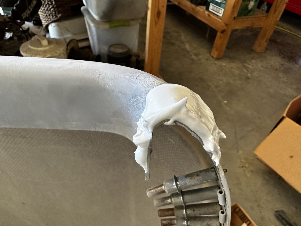
OK, so about that layup on the upper cowl. I decided I didn’t like how the gap ended up between the right side of the upper cowl and the firewall, so I wanted to add some material so I could rework the gap. The basic idea here was to sand a scarf joint and lay up a bunch of layers of cloth to overhang the edge. To get the contour of the cowl right, I clecoed a piece of aluminum scrap in place on the outside and covered it with packing tape to keep the fiberglass from sticking:

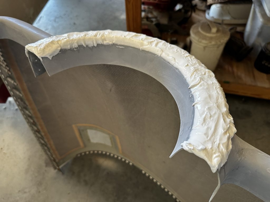
Then I laid up eight layers of cloth on the inside, which should give me about the same thickness as the original cowl edge. Once this cures, I’ll have a lot of sanding to do to clean up the scarf joint here, before I even get to working on the actual edge:

Finally, while working on other stuff, I had an idea for improving the cowl alignment at the firewall. The basic issue here is that the very upper edge of the lower cowl is unsupported, along with about a 6” portion of the upper cowl in the same area. So while everything else is pulled into nice alignment the upper edge of the lower cowl sits a bit proud of the fuselage skin:

The construction manual suggests possibly drilling a hole in the firewall for the hinge pin to slide into, this providing some additional support for this area. That seems like a decent idea, but I’m not a big fan of unsealed holes in my firewall, no matter how small they are. But I realized that I might be able to add some aluminum blocks inside the firewall flange, which could in turn force the pins inboard and pull the cowl edge into alignment.
Some experimentation with scrap from my panel cutout looked promising, so I cut a couple pieces and match drilled them. I also added a taper on the forward edge of the spacers, to help guide the pins into place as they’re inserted. These pieces still need some final trimming and cleanup, but the idea seems sound:

Much better alignment with the spacer in place:

I guess the next order of business will be cleaning up that flange extension – as mentioned, lots of fun sanding in the works there. Then maybe I’ll see about riveting all these assorted hinges in place…