Firewall Forward

Fuel system planning

OK, so today I completely changed gears and didn’t do any more ignition-related work – instead I got to playing around with fuel-related stuff. Ever since I received the engine, I’ve been bothered by the routing of the supply line to the throttle body. This line goes from the mechanical pump at the back left of the engine, and just sort of hangs underneath the sump on its way forward. That’s not great because…that’s where the exhaust will be.

This was one thing I was interested in while looking at RVs at Oshkosh. One I saw with the cowl off had a pretty obvious solution – just route the line around one side of the engine, above the intake runners. But that plane had a different fuel injection setup from mine, so it still required some thinking on my part. That setup had the throttle body inlet on the middle left side, whereas mine is low on the right side. That’d make for some interesting routing to get the line up above the intake runners.

However, while looking over documentation on my injection setup, I found an example photo that showed a really simple solution. The throttle body doesn’t have to be oriented any particular way, and in this example photo it was rotated 90° from my orientation. This moves the fuel inlet to be high on the right side. A quick test run of this setup showed that it makes for great positioning of the inlet – the hose is at the perfect level to route around the right side above the runners:

An additional benefit is that after moving the throttle arm to the opposite side of the body, both it and the mixture arm are in a great position to mate with the control cables, which can come right underneath the oil sump:

And at the back of the engine, the hose has plenty of room, as well as plenty of spots to secure it along the way:

The only thing that was going to be odd about this was connecting the hose to the mechanical pump. This came with 45° fittings on both the inlet and outlet side, which weren’t ideal for my new arrangement. But I figured that’d be easy to solve, I could just find the right 90° replacement fitting. Fortunately, before I added that to my shopping list, I went to go looking through the FWF kit to see what hoses were in there – mainly I was thinking of the feed hose from the throttle body to the flow divider on top of the engine. Turns out there are already two of the 90° fittings I need in there. I should probably look in that kit more often, this surely isn’t the last challenge I’ll try to puzzle out on my own unnecessarily.

The one thing I haven’t decided yet is whether I want to get a new supply hose. The one I have is the right length, but would need another 90° adapter on the fuel pump end. This would be easy enough to get, but I’m kind of wondering if it would be better to get a new hose with 90° fittings on each end. This way, I could eliminate two adapters, both of which are additional potential leak points. The downside of this approach is that a new hose is…let’s just say quite a bit more expensive than an adapter. Then again, I could probably resell the hose I have now and recoup some money.

Anyway, that’s where I’m at today. I’m holding off on my Spruce order for the time being; I want to look at my firewall component mounting and see if I may need some additional hardware for those items. It’d be nice to get as much stuff on hand as possible, so I can roll with the momentum I’m feeling right now. Mounting everything on the firewall means I can be free to re-hang the engine when I’m ready, which will in turn allow me to start working on really fun stuff like control cables, engine sensor wiring, and so on.

Posted in Firewall Forward | Hours Logged: 2

Hall sensor install

Seems like it’s been tough to find shop time recently…we’ve got a lot of stuff going on weeknights, and even weekends get busy sometimes. I did get some time in Sunday afternoon, though, which is where most of what I’m writing about here happened. It was just this afternoon that I finished up this bit of work and decided it was worth writing about.

As mentioned previously (I think), I wanted to make a wire guard for the SDS hall sensor. Most folks seem to add some protection here – if the alternator belt fails, it’d be A Bad Thing for it to take out this sensor wiring as well. I followed the lead of other folks here, using some aluminum angle to fabricate the guard. The sensor mount includes a few different 3/16 threaded holes for mounting guards, which I took advantage of. Most of the work here was just laying out the cutout for the wires to pass through, then fine-tuning it for proper fit. Lots of drilling, dremel-ing, and filing.

Also, another fun part of this work – remember all those repeated tries the other day to get the safety wiring job on the sensor mount to my satisfaction? It was pretty clear that the best way to fit this guard was with the sensor mount removed, so I cut off that safety wire work, which made me a tiny bit sad.

Anyway, here’s a look at the backside of the finished guard, showing the two mount bolts. This was just a temporary assembly – for final assembly, both these bolts got lock washers and torque seal for good measure.

Next, a look at the reinstalled mount with the guard and sensor installed:

The next question is where/how to route the sensor wires. I’m thinking about first securing them to the prop oil line (seen in the left of the photo above), but the question is whether they should then go above or below the cylinders. I’m pretty sure above is the right answer, but like all things FWF, it’s something else to go read about.

In other good news, I got my Spruce order in, which includes some raw materials I needed, plus the hardware with which to finally mount my mag-pad coil pack, plus the blanking plate for the other mag pad. I’ve also got my new fuel hoses from AS Specialty coming in Thursday, so I should be able to finalize the fuel line routing this weekend.

I’m thinking I’m pretty close to wanting to hang the engine on the fuselage again, mainly so I can finalize planning the battery box mount and other firewall stuff. I figure I’ll remove the engine one more time to have room to work on that stuff, and then I’ll hang it for good, and start thinking about routing wires and so forth through the firewall…

Posted in Firewall Forward | Hours Logged: 3

Fuel transducer futzing, other miscellaneous stuff

So…I picked up on engine work yesterday, with the intent of installing the fuel flow transducer, along with the short fuel hose between it and the throttle body. Let’s just say that I vastly underestimated the challenges in getting that thing mounted. I’m using a mount kit that I got from AS Flightlines, which includes a little bracket that bolts to the engine case and houses the transducer itself.

The challenges here are multiple: First, the transducer is a very tight fit in the bracket…to the point that I couldn’t get it in far enough for the mount bolt holes to line up. Second, with the bracket mounted on the case, it’s impossible to even get the through bolts in due to the proximity of the pushrod tubes. That second issue could be fixed by installing the transducer into the mount off the engine, but then the bolt to attach the bracket to the engine is behind the transducer.

Eventually I gave up in frustration and made a post on VAF to try and figure out if I was doing something wrong. Much to my surprise, I got an email this morning from Tom Swearingen, the vendor in question, with some tips for getting the thing installed. While this helped quite a bit, I still was never able to get the thing installed today. The basic procedure is to loosely install the bracket, insert the transducer (side note: I just needed a bit more force to solve Problem #1 above), then rotate the entire assembly to where the upper through bolt can be inserted, thus solving Problem #2.

This still leaves a significant challenge, which is figuring out how to tighten that mount bolt. Tom suggested that it could be done with a stubby wrench and “some patience,” but I was never able to even get a wrench on the thing once, much less the who-knows-how-many times I’d need to snug the bolt up. I think I have a solution to this, involving some modifications to a cheap combination wrench, but I need to get a better torch for the heating & bending portion of that program, so I’ll have to try and pick back up on this tomorrow.

Having set that aside for the day, I decided to move on to some other minor stuff. I got out my neat little safety-wire jig and used it to drill two opposite corners of the oil temp sensor, after which I final-torqued it and worked on safety wiring. My initial plan was to safety the sensor to the vernatherm right below it, but the relative positions were such that the wire wanted to slide off the back of the sensor. Instead I used the two provided holes in the filter adapter and safetied each item individually:

Although now that I look at this photo, I safetied the vernatherm the wrong way. Well, that’s kinda embarrassing…

Next, I moved on to the magneto pads. My Spruce order included the hardware required to take care of this stuff, so first up I installed the blanking plate on the right-side pad:

The left side gets the coil pack base plate, installed using two nicely machined hold-downs:

And then the coil pack mount gets bolted onto the base plate:

Those three bolts still need to be safety-wired, but I think I’ll remove the coil pack from its mount to do that – that’s gonna be some tight-quarters work.

So that’s it for tonight, though I think now I’m going to go out and fix that safety-wire job on the vernatherm, before I forget about it…

Posted in Firewall Forward | Hours Logged: 4.5

Transducer install complete!

It’s funny how a task that seems nigh-impossible can suddenly become really easy once you introduce the proper tool. That’s basically the story of today. When we left off yesterday I’d decided to try bending a cheap Harbor Freight wrench to make a special tool for installing the transducer. Today, while I was out, I picked up a nicer Mapp gas torch, and when I got home, I went to town on said wrench.

In the end, I basically put one 90° bend, plus a second smaller one. Combined with the existing angle of the box end of the wrench, the result is basically a U-shaped wrench that clears the AN fitting on the bottom of the transducer. In addition to the bending, I also did some grinding on the box end, thinning it out to better work in the tight confines of the mount bracket:

Armed with this device, it took me barely half an hour to get the transducer installed. Those hours of futzing with a stubby wrench were replaced by about five minutes of carefully maneuvering my special tool in between the cylinders:

So now I have the plumbing between the throttle body and the flow divider complete. Just need to add some torque seal on those fittings:

The other thing I got done tonight was safety wiring those ignition coil mount bolts. This is definitely not the best work I’ve done, but it’s almost impossible to get good angles on things in this tight spot. I’m honestly kind of inclined to install lock washers here in place of the safety wire, but I think even a not-great safety wire job is probably more secure than a lock washer, so I’m leaving it like this for now:

My second fuel supply hose shipped today, so hopefully I should have that this week. At that point I can finish this plumbing work, and I think it’ll be time to hang this thing on the fuselage again to finish the firewall layout.

Posted in Firewall Forward | Hours Logged: 1

Fuel line routing/install

OK, so yesterday I got my (second) fuel hose from AS Flightlines, and this time I got the hose size right. Getting it installed and properly secured seemed like a nice little evening task. The routing was easy since I’d previously figured out the general idea, and just needed to tweak some things a bit, most notably the clocking of the 90° fitting on the outlet side of the mechanical pump.

The real fun was in securing the hose. I had two points where I wanted to use double adel clamps, one on a mount tube and the other on an intake pipe. Thing is, adel clamps are kind of fun to work with – you’ve got to squeeze the ears closed and hold the thing in place while also putting a bolt through it and starting a nut. And that’s just one clamp – with this setup, I had to do that with two clamps at once.

Fortunately I’d previously read about a technique for handling this – using safety wire to hold the ears of each clamp together. I’d hoped this would be a way to use up the really fine wire that came in my safety-wire kit, but turns out that stuff isn’t stiff enough to really pull the clamp ears together. Oh well.

Anyway, things are wrapped up now. The line exits the pump, then heads over to the right side of the engine. It gets secured to a mount tube as it crosses under:

Then it makes the turn forward and is secured to the #3 intake pipe:

And finally it loops around front to the injection servo. I’d initially thought I’d secure it to the prop oil line (the hard tube visible nearby), but there doesn’t seem to be enough freedom of movement here for there to be a chafing issue. It’s possible I might change my mind in that, though:

The rest of the work was getting the end fittings torqued, along with the clocking and torquing the 90° adapter fitting on the pump.

I did run into one possible hangup, though, which can be seen back in the first photo. Van’s provides another 90° adapter fitting on the inlet side of the pump, and I figured I’d replace the 45° one that came with the engine while I was in the neighborhood. Unfortunately, trying to thread it out of the pump, it interferes with the governor mounting pad after only about one turn. The only way to remove that fitting seems to be to loosen and/or remove the mechanical pump.

I’m hoping I can get by with the 45° fitting and not deal with removing the pump – I suppose once i get this hung on the fuselage again, doing a test-fit of that fuel line will be on the short list of things to do.

Posted in Firewall Forward | Hours Logged: 1

Flywheel magnet install, baffle tinkering

Today I decided to start by working on the other half of the flywheel-area stuff for the SDS ignition. Previously I installed the hall sensor, now I just needed the actual magnets in the flywheel to trigger that sensor. The procedure itself is fairly straightforward, and Ross provides both clear instructions and a nice drill block for the job, but there’s still a bit of nervousness that comes with poking holes in a shiny and no doubt expensive engine part.

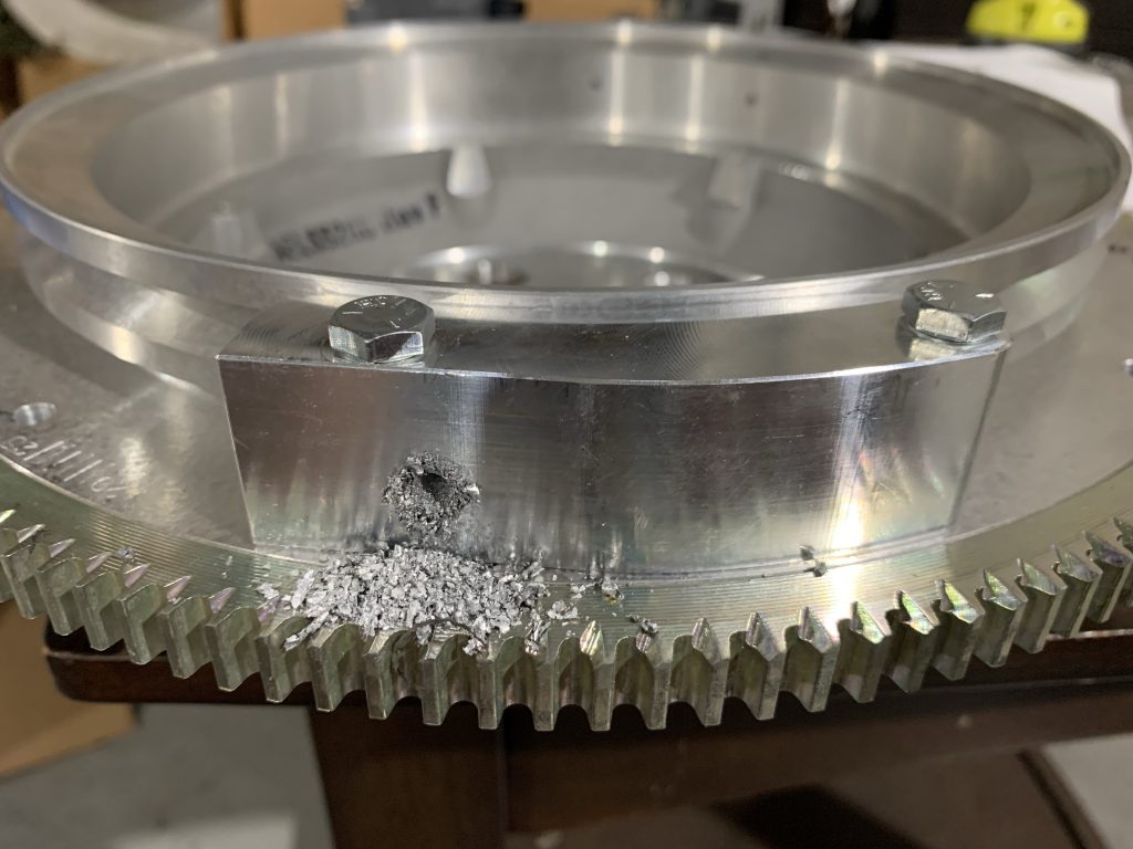
In short, the procedure calls for installing two trigger magnets 180° apart, plus a sync magnet near the first trigger magnet. Existing holes in the flywheel are used, along with the timing marks, to position the drill block in the three required positions. At each spot, the block is secured with a pair of bolts, and then it’s drilling time. We’re going through a good 3/4” or so of material, so it takes a bit of time for each hole, and you end up with plenty of chips:

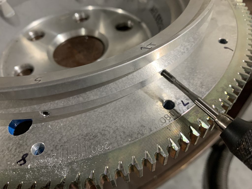
Next, after drilling all the holes, each one gets tapped for an allen-head set screw, which will be used to put the magnet in the proper radial position. Note the markings inside the flywheel; this is the #1 trigger hole I’m tapping, with the sync hole just to the left:

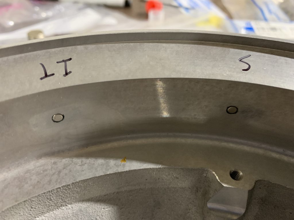
Next, we install the set screws, and test fit a magnet in each hole, adjusting the screw until the magnet sits flush with the inside flywheel surface. Finally, we remove the magnets, mix up some epoxy, then dab it in each hole before reinstalling the magnets:

There is one last step, which doesn’t merit a photo: after letting the epoxy cure, a second set screw is installed in each hole, with a bit of Loctite, thus providing some extra security that nothing will come loose.

After having some dinner, I decided to start looking at the engine baffling. I actually unpacked all this stuff a couple nights ago with the intent of doing this, but got slightly intimidated at the sheer number of parts and had one of those moments where I had to set it aside and come back with a clearer head. As per usual, the second look at the parts and plans made things seem a lot clearer. It was still obvious that I wasn’t going to start really assembling any of this stuff yet, but I did want to get a big-picture idea of how it would all fit around the engine, to identify any issues I might have with all the other systems stuff I’m doing. Sure enough, a few things presented themselves immediately.

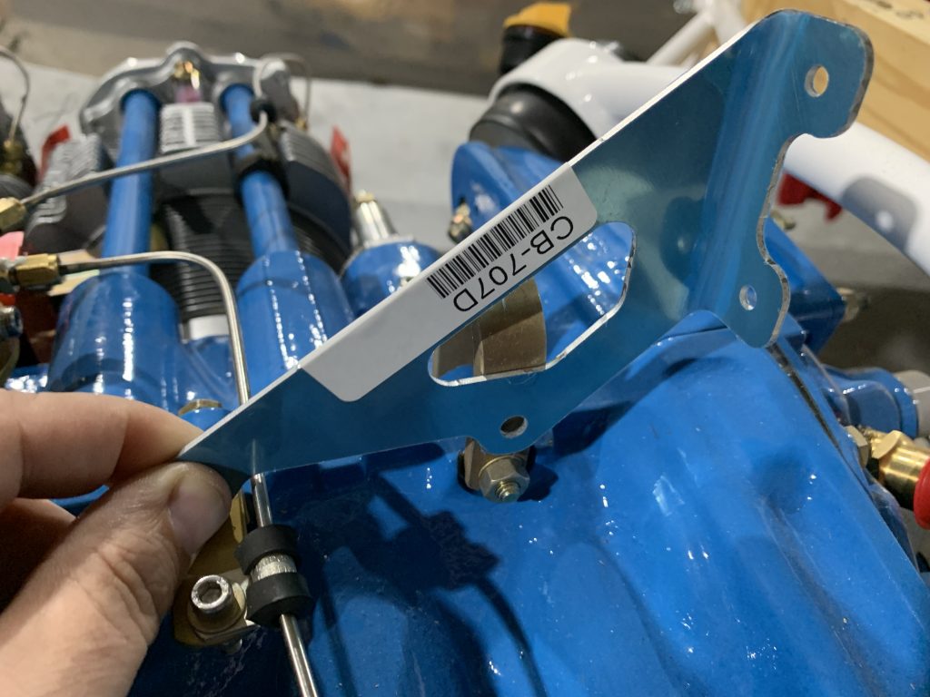
The first item is at the rear of the case. Here, the vertical back portion of the baffling is braced against the case with a little gusset piece, which uses the two rear upper case bolts to attach to the engine. This it notable because these are the same two bolts I was going to use for the coil pack mount. This probably isn’t a super difficult job to solve, but I definitely won’t be using this piece – I’ll need to fab up something that will end up being part of the coil pack mount.

The next item is one that I knew was coming, but is still worth noting. Most Lycoming cylinders have fins at the base with a, well, cylindrical profile. Titan/ECI cylinders, on the other hand, have a tapered/conical profile. The result is that the provided baffle pieces in this area won’t fit the Titan cylinders very well.

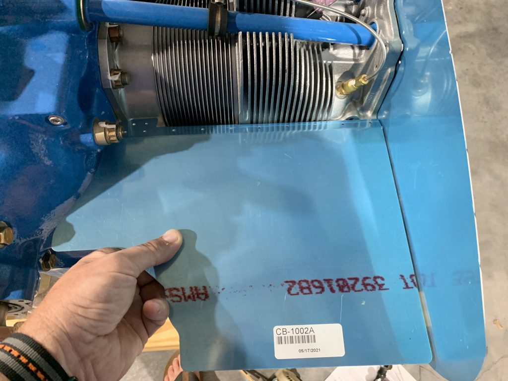
Here’s one example; we’re looking at the #2 (left front) cylinder. The piece I’m holding will form a ramp between the cylinder and the air inlet on that side of the cowl. Keep in mind that the purpose of all this baffling is to force the flow of cooling air as close to the cylinders as possible:

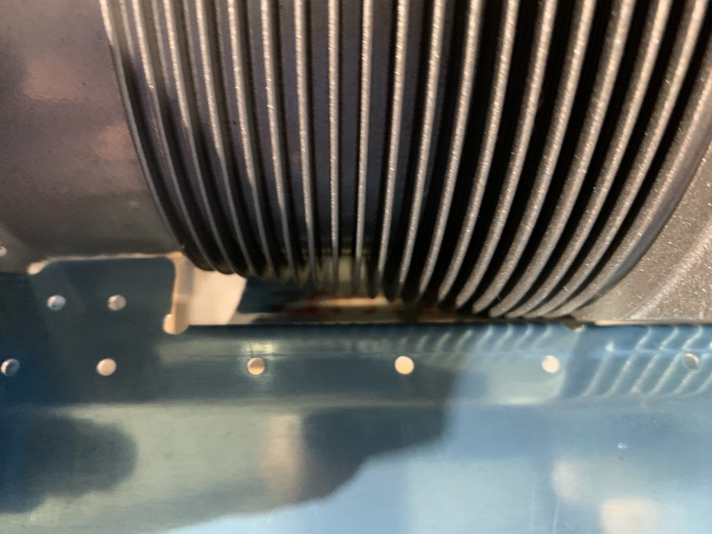
The issue is more obvious in a close-up photo: the gap between the baffle and the tapered cylinder is evident here. This is an area where air isn’t going to be kept close to the cylinder. Also somewhat visible is a curved piece of material that wraps around the cylinder; this also isn’t going to fit close to the fins.

A similar issue will exist at three other places: on the other inlet ramp to #1 cylinder, plus similar pieces that butt up to the #3 and #4 cylinders at the back of the engine. Fortunately, this is a solved problem; previous builders have fabricated new pieces to better fit the conical profile, and even have templates available online to cut these pieces. The existing wraparound bits will be cut off and the new pieces riveted in their place.

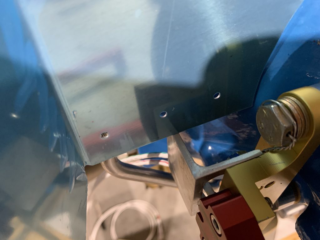
Finally, we come to the front of the engine. Here we have another vertical piece, which fits tightly around the case just behind the crank snout. Another wide shot gives an idea of the big picture:

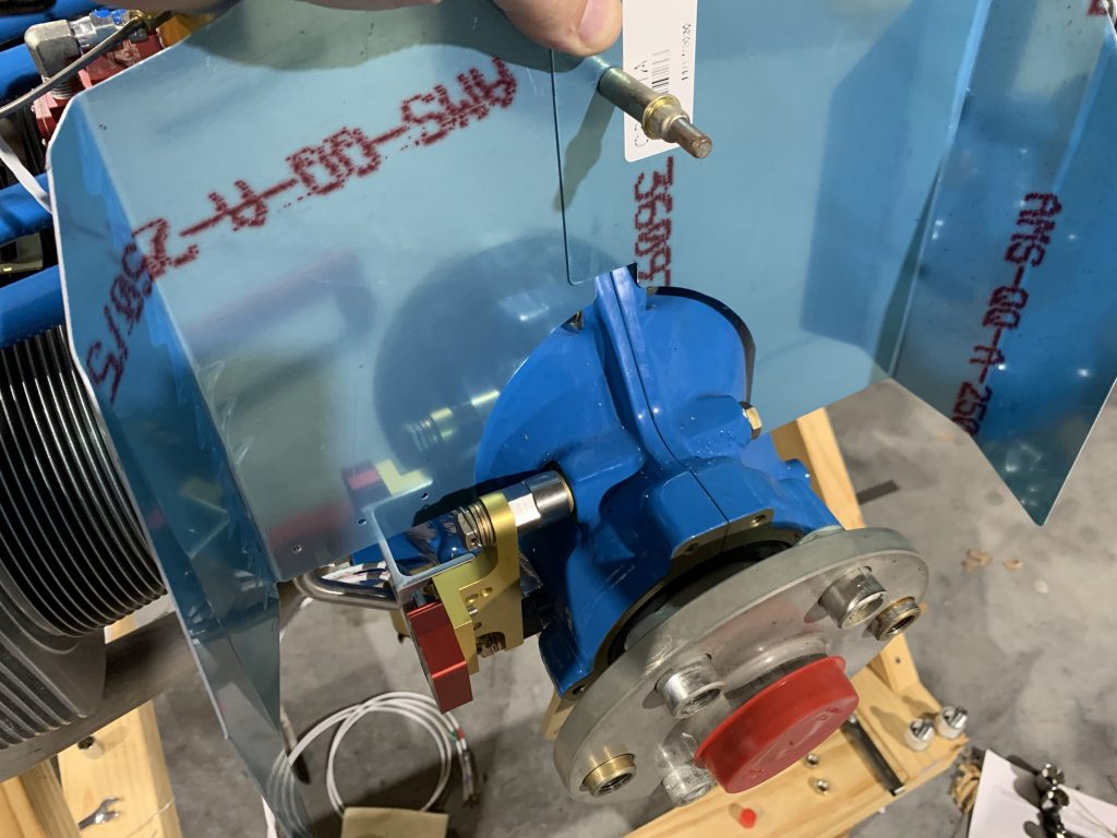
Moving closer, we can see the issue here – that nice big cable guard I made for the hall sensor protrudes too far back. I can’t even slide this piece down to where it’s supposed to be with that guard in place. So I’ll have to remove that when the time comes to fit the baffling, and get it trimmed to fit better:

All this baffling stuff also raises some order-of-operation concerns. I’ve been holding off on riveting the forward upper skin in place until I can finalize the wiring runs. Finalizing those runs requires getting the engine hung and at least some of the wiring fed through, most notably the ignition stuff. Finalizing those runs in the engine compartment, in turn, will probably require doing some baffle fitting to handle spots where the runs will need to penetrate the baffling. It’s possible that properly fitting the baffling will require having the cowl in place. And I don’t think I can fit the cowl until…the forward top skin is riveted. Maybe. I’m not at all sure there’s actually a problem here, but it’s going to be a thing to keep in the back of my head while mucking with FWF stuff.

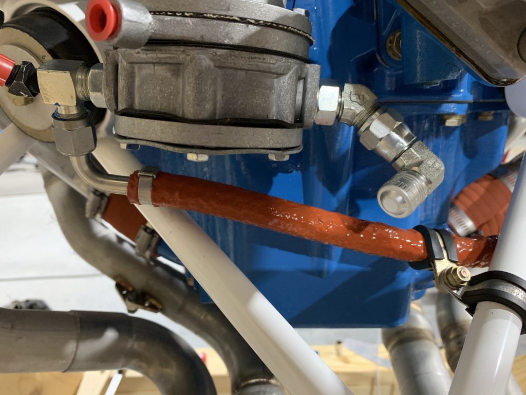
Ok, enough of that…let’s get on to a few more minor items. Last time I was concerned about the mechanical fuel pump’s inlet fitting, which I couldn’t remove without removing the pump itself. The main concern I had about plumbing with the provided 45° fitting in place was that the fitting is pointing to the right side of the aircraft, whereas the firewall penetration for fuel supply is located to the left of the pump. That is, a slight difference in fitting orientation could require a somewhat longer fuel line.

However, a potential solution occurred to me: I had an extra 90° AN adapter, which was originally installed on the injection servo. Since the custom hose I got has 90° fittings on each end, that adapter was now unused…and adding it to the inlet fitting means I now have a potentially straighter shot to the firewall penetration. This would also give a lot more freedom for orienting this fitting to work nicely with the line. It’s still something to test fit next time I hang the engine, but I feel really confident I can make this work without having to remove and then reinstall the pump:

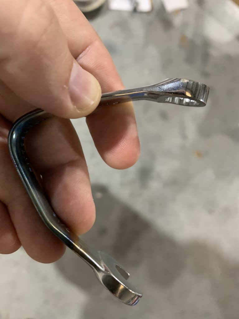
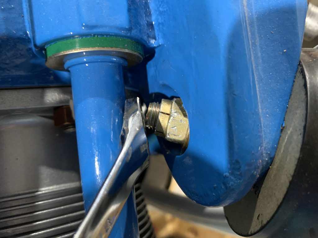
The last item was fixing a long-incomplete task. Back when I first got the engine installed on the mount, I was only able to fully tighten three of the four mount bolts. For the fourth, the nut on the forward side of the mount was super close to the #4 pushrod tube. I could get a wrench on it to start tightening the bolt, but as more and more of the bolt protruded, it would end up trapping my box end wrench. And there’s no room to use the open end in the engine case recess.

This was actually why I originally bought that cheap wrench set – the same one I grabbed the 7/16” wrench for to make my torch-bent tool earlier this week. Tonight I finally got around to grinding the 5/8” box end down to a really slim head, which can fit in the tight space and allow the bolt to be properly torqued:

Whew! That was a lot of writing for a relatively small amount of shop time. I think it may be about time to hang this engine again and start working on some of the fitting/locating work that requires it in place. Maybe that’s what I’ll get to tomorrow.

Posted in Firewall Forward | Hours Logged: 2

Engine re-hang, firewall layout

Well, not a ton of shop time today thanks to other stuff going on (including unexpected mower maintenance), but I still got some stuff done. I decided it was high time to move the engine back to the fuselage so I could finalize things like the battery box location. Moving the engine took a bit more time than I expected…but still better than the initial hack getting it bolted to the mount.

The next bit of fun was playing with the battery box. I already knew that I wanted to mount it low on the right side of the firewall, but there were a couple questions still to answer, mainly 1) exactly how low to mount it and 2) whether to orient it with the top of the battery up or sideways. There’s also the consideration of being able to tie the backer plate I’ll be making for the box into the firewall angles.

To make a long story short, I’m going to mount the box sideways. With the top up, the upper left engine mount tubes become problematic for getting the battery in and out, unless the battery either goes so far to the center as to make the backing plate a problem, or so low that tying into the lower angle is also a challenge.

The downside to this position is that the firewall flange will be in the way of removing the battery, which means that I’ll have to loosen the mount bolts to the firewall for battery service. This will be mildly annoying, but not horribly so; with the box so close to the edge, access should be very good here.

The other thing I wanted to verify was the fuel hose routing from the firewall to the mechanical pump. This was to verify that the fittings I had would allow for suitable routing – I was pretty sure I could make it work, but definitely wanted to verify. And I’m happy to say that it looks just fine:

I suppose next steps will be to draw the final location of the battery box, the start looking at where I want to put the master/starter contractors, the battery bus fuse block, and the E-bus relay. Once I get the layout finalized…I get to remove the engine yet again and start working out actual mount hardware and such.

Posted in Firewall Forward | Hours Logged: 1.5

Still playing with the firewall layout

Well, the work ethic still hasn’t been great, but I keep trying to chip away. Over this past weekend I did some more poking around with how to lay out firewall stuff. Deciding on the battery box position and orientation was helpful, but there was still the question of other electrical stuff. Specifically, I also need to locate the master and starter contractors, the ammeter shunt, a big fat ANL fuse to protect the alternator B-leads as well as the supply line to the fuse blocks inside the cockpit, plus the battery bus and e-bus relay.

Basically, there’s a bunch of stuff here and a lot of considerations. I’d like to avoid placing anything so that it’s a huge pain to access for service. At one point I was considering locating the ANL holder and shunt inboard of the battery box, but that would mean that if that big ANL fuse ever popped, I’d have to pull the whole cowl and probably crawl under the airplane to service it.

The contactor locations, at least, were straightforward: I can place both of them just above the battery box. The battery bus and e-bus relay can probably go basically anywhere; they barely weigh anything and thus I don’t need to worry a lot about the structure they’re attached to. But positioning that ANL holder and shunt was giving me fits.

I eventually arrived at a somewhat obvious solution – namely, neither of those need to be mounted to the firewall. And since they’re both sort of oblong pieces, each with two large screw holes, they’re good candidates for just mounting on an engine mount tube with adel clamps. I tried a few different spots, and for the moment they’re living on one of the upper tubes. I think this location should be good, though one of the fun things in the back of my head is where lots of other wires and things are eventually going to be routed.

Still, I feel good enough about this to go ahead and work on the mount plate for the battery box and contactors. I think the biggest obstacle for that is going to be getting over my reluctance to go drill holes in the firewall, but it’s got to be done.

I also did some other tinkering along the way; for example, I wanted to have some general mental picture of where the fuel and oil lines to the pressure sender manifold would live. That required some digging into plans and researching. (example: where does the oil pressure sender line even connect?)

In any case, I think this is the point where there’s nothing for me to do but to pull the engine back off and get going on that battery mount. I’ll also want to drill the holes for the control cable passthroughs while the engine is out of the way. One of these evenings I’ll work up the wherewithal to do it…

Posted in Firewall Forward | Hours Logged: 3

Even more firewall layout

Yes, it’s me again. I guess the motivation switch has flipped again and I’m back to doing stuff. Basically, I’m continuing with the goal of finishing layout stuff that I want the engine in place for; once that’s done, I’ll remove it again to provide good access for poking holes and such into the firewall, and then when it goes back on it can be permanent.

One thing I’ve been mulling over a bit for a week or so has been the location and layout of the pressure sender manifold. This little dude gets mounted on the firewall, with incoming lines for fuel and oil pressure, and then the actual pressure senders get attached as well. An interesting tidbit here is the orientation of this device. For whatever reason, the OP plans for an injected engine call for placing the manifold vertically, and adding a small stiffener on the backside of the firewall for support. The carbureted OP plans, on the other hand, place it horizontally, and the existing firewall angle provided support.

It seems to me that it’d be much easier to use the horizontal placement and not have to add an extra piece. I asked around on the Van’s forum and there seems to be no reason for the orientation difference, and plenty of people have done the horizontal setup, so that’s why I’m going with. So I installed the oil pressure fitting on the engine block, installed the fittings on the manifold, and put the hoses in place. This allowed me to experiment with placement, and ensure that I liked the way the houses were routed.

With a little bit of trial and error, I worked out the location I wanted, as well as which two of the three manifold ports I’d be using. This will be ready for the mount points to be drilled once the engine comes off:

Next was the age-old problem – working out the battery mount area. I’ve mulled this one to death, over and over again, and it’s past time to stop mulling and start doing. At first I was going to use some cardboard to mock up the mount plate, but given that things are pretty straightforward here, I decided to go straight to cutting on one of my sheet pieces I bought for this. Here again, it took a bit of trial and error to get the angles to match like I wanted, but I’ve at least got this roughly cut the way I want it:

My general idea of how to go from here will be to find a way to fix this in place on the firewall, and then do a full mockup with the battery box, as well as the master and starter contactors. Once I get that done and I’m happy with the layout, I think it’ll be time to pull the engine and start making holes…which is a little scary, but it’s got to be done.

Posted in Firewall Forward | Hours Logged: 2

Battery mount layout

So as alluded to last time, the work since then has revolved around nailing down the battery box mount layout. Basically, I did some incremental trimming on the mount plate I rough-cut last time out, and then transferred some of the location lines I’d drawn on the firewall onto it – stuff like rivet locations and a line I drew to approximate where I wanted the battery box to go.

This mount is actually going to sort of do double duty – in addition to mounting the battery box, I’ll be mounting the master and starter contactors on this plate as well. So that makes for some additional layout work to be done, much of which I was firming up earlier this week.

Today i transitioned into figuring out exactly how I wanted to mount the plate to the firewall. The general plan has always been to remove a few of the existing rivets and enlarge their holes for bolts instead. Today I was figuring out which of these existing holes to use – ensuring I picked ones that wouldn’t interfere with the battery or the contactors, roughing out those locations on the plate, double-checking things…let’s just say “multiple” times.

Finally, I was happy with the rough layout, to the point that I felt like it was time for the engine to get out of the way – so I brought over the engine fixture and pulled that beast off, hopefully for the last time. With it out of the way, I can get to work on finalizing a few different firewall items. The most obvious of these are the battery mount and pressure manifold, but there were also a couple rivet hole that I never filled before for some reason, plus I want to fit the eyeball passthroughs for the control cables. So my first order of business after removing the engine was to mark up all this stuff on the firewall, as a sort of visual checklist.

Those missing rivets got taken care of first up, then I moved to removing the rivets where the battery mount holes will go. With those out of the way, it seemed like a good time to call it a night. The next order of business will be to figure out how to hold the mount in place while I use the rivet holes to drill #30 pilots into the mount – that will fix its location, and once that’s done I’ll drill them to final size, then get to finalizing the mount itself.

Posted in Firewall Forward | Hours Logged: 2.5