So with new parts in hand, I got right to work this evening. It was a good night for it, too – some rain during the day today seems to have dropped the temperature nicely.
The funny thing is, I waited until today to work on this so I could print out the updated construction manual pages, and then I proceeded to mostly ignore them today. They seem to be kind of inaccurate, actually – for example, they speak of drawing rivet lines on the doublers to help lay out the holes, but the doublers I got are already almost totally prepunched, so there’s no leeway to play with spacing here.
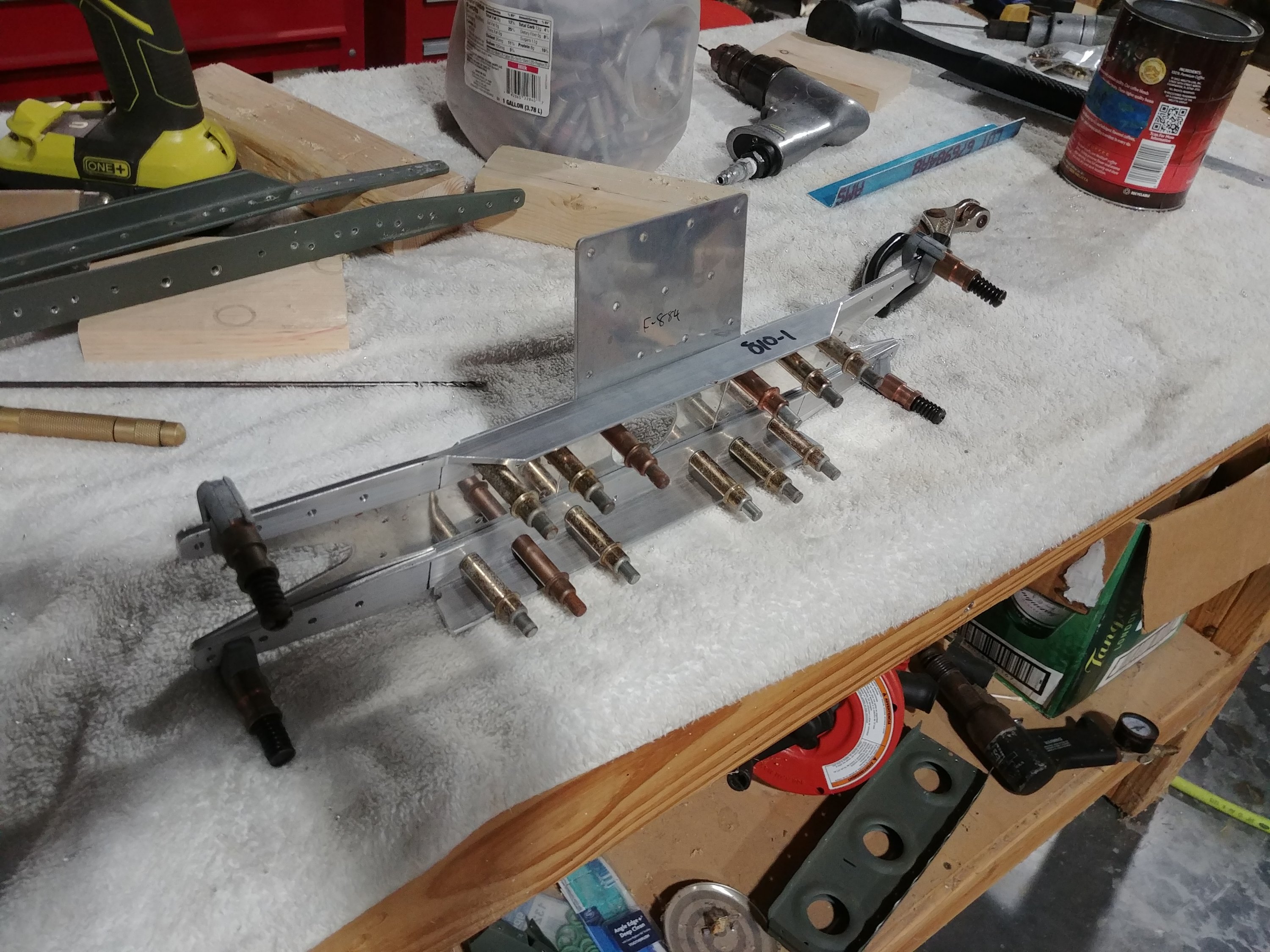
With that in mind, I decided to start by drilling the reinforcing angles to the spar channels – at least the center holes, inboard of where the channels will get bent to match the sweep of the spar. Doing this meant I had the holes in place that I needed to cleco the doublers and the v-stab splice plate in place to see how everything fit together. As you’d expect from prepunched parts, there was no interference between anything.
Next, I removed the reinforcement angles and marked the required tapers on their ends, then made the tapers. I rough-cut on the band saw, cleaned up the long cut lines with a vixen file, and then used the scotchbrite wheel to round the corners and clean everything up.
With that done, I got to thinking about how I could verify that I’d have good edge distance on the new doublers. Seeing as how they’re prepunched, I figured they ought to be fine, but since I’m rebuilding after ruining the old spar, I’m feeling a bit conservative with this stuff. The only holes that aren’t prepunched in the doublers are those in assembly with the inboard ribs, and those that will match the outboard holes the angles (outboard of the bend line). Those outboard holes aren’t prepunched in the spar; they get drilled in assembly with the angles. That meant I couldn’t easily mark the prospective hole locations on the doublers either…hmm.
Then it hit me…I could just cleco the angles to the splice plate and doublers, without the spar involved. The alignment wouldn’t be precisely the same as when everything is together, but it’d be plenty good enough for verifying the edge distance. And it was super easy to do:

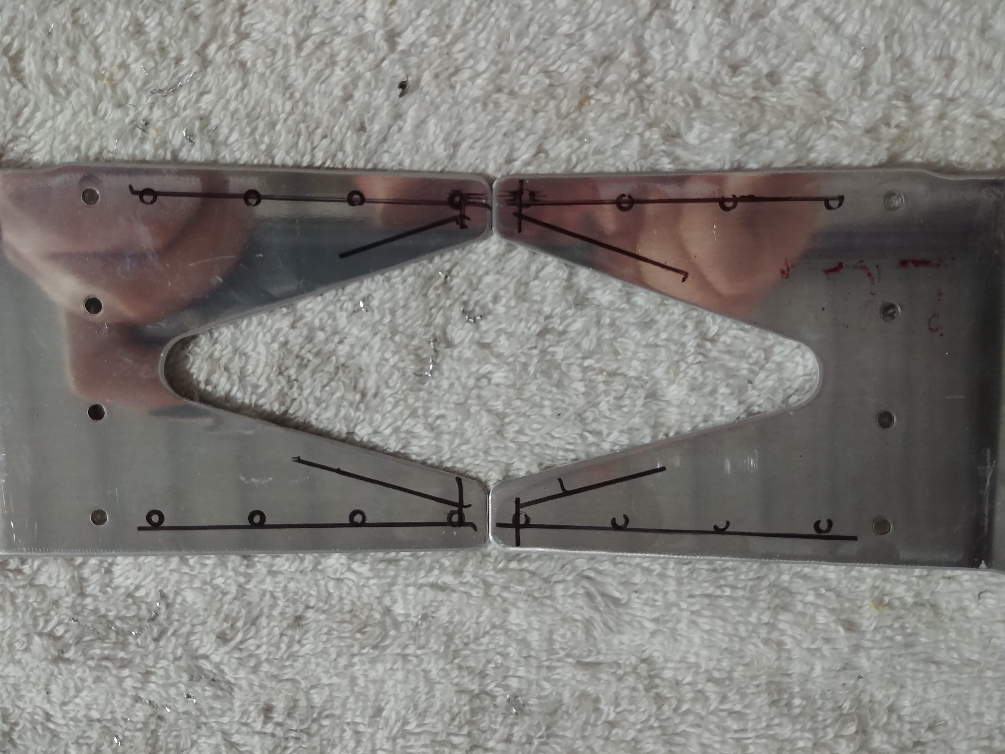
So I marked the holes, disassembled everything, and then marked an edge distance line around the perimeter of the doublers. The results are not really what I’d hoped for, though. The holes on the bottom are OK, but the top is a different matter. The inboard holes are slightly out of spec, but the outboard ones are way worse. The edge distance lines drawn here shouldn’t overlap the edges of the holes:

So now I get to decide how to handle this. I can only think of two real options: first, accept the edge distance as it is and build on. Second, try and modify the upper angle a bit to tweak the holes downwards. That second option actually isn’t as wacky as it sounds at first. The angles already have to be bent to match the swept portion of the spar – I could maybe apply the mallet to bend the “ears” down a bit to migrate those holes. It wouldn’t take much at all, really…but it is still finagling with a kind-of important structural piece.
And of course I had to hit this on a Friday night, when there will be no Van’s support available until Monday. I guess I’ll start by asking around on VAF and see what kind of stuff I hear. I really don’t want to stop work for the weekend…
UPDATE: Actually, this isn’t as bad as I thought. The common rule of thumb for rivet edge distance is 2x the rivet diameter to the hole center, or 1.5x the diameter to the edge of the hole. However, a closer look at the mil-specs provides a more precise number…specifically, for 1/8” rivets, the minimum distance to the hole center is 0.219”, or about 7/32”. Using that number, and measuring with my calipers (much more accurate the two sharpie lines), I’m find on edge distance everywhere except the inboard most hole on that top angle, and in that case it’s barely out of spec. With that in mind, I’m going to build on.