So, it turns out that bending hard lines is…somewhat challenging. I kind of knew that would be the case, but I was maybe a bit too buoyed by the first line I made a couple days ago. Suffice it to say that I made a lot of scrap material today. Still, I almost got all the lines done with the material I had on hand, but for one final annoying foul-up…more on that in a bit.
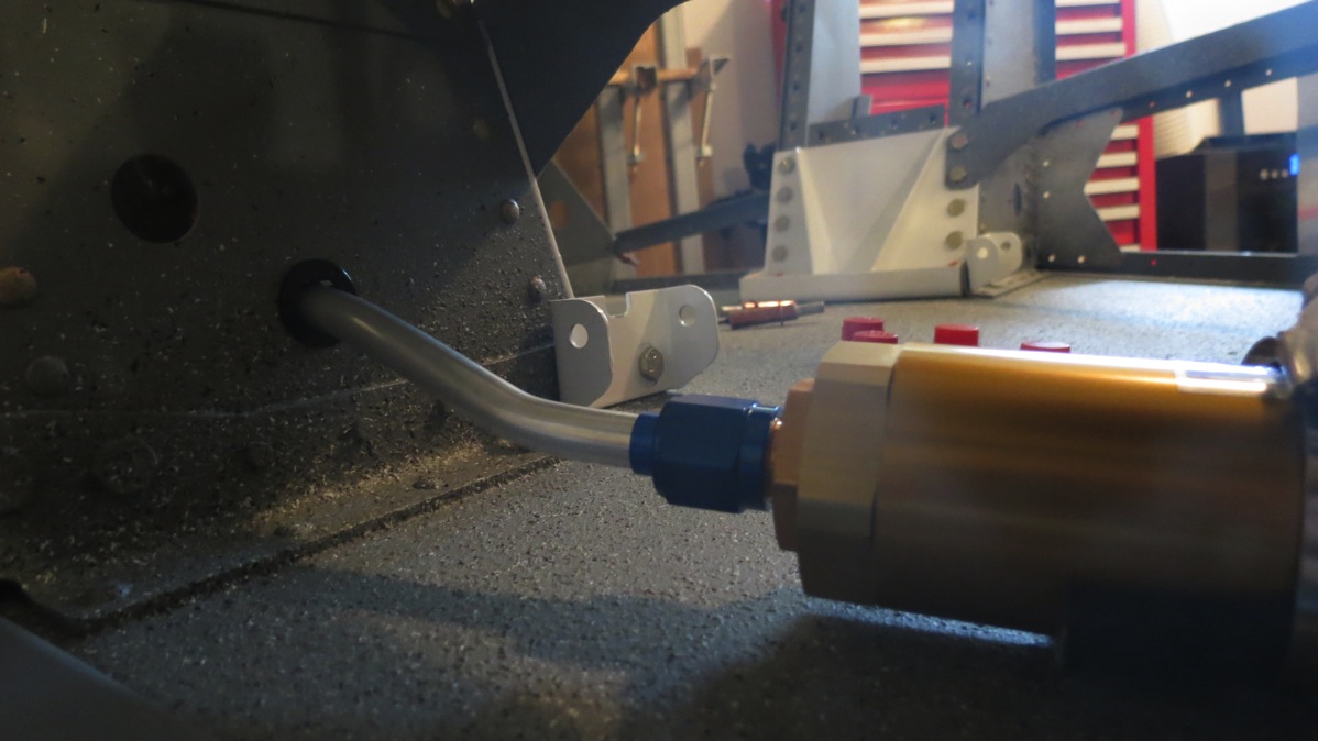
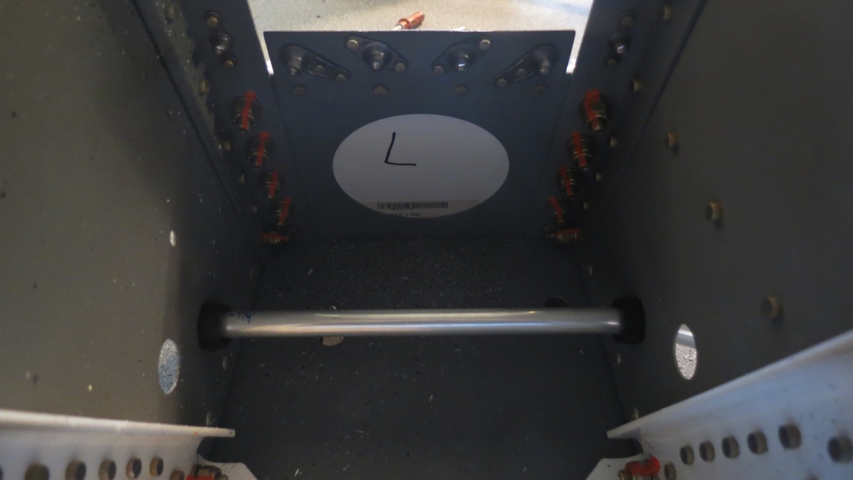
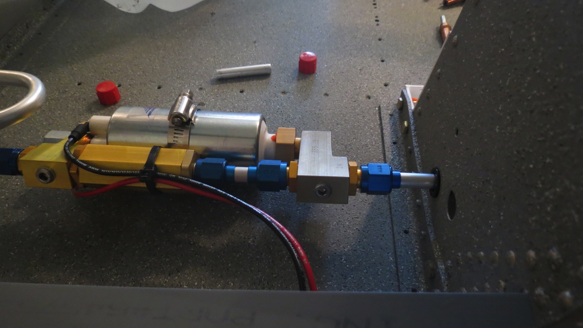
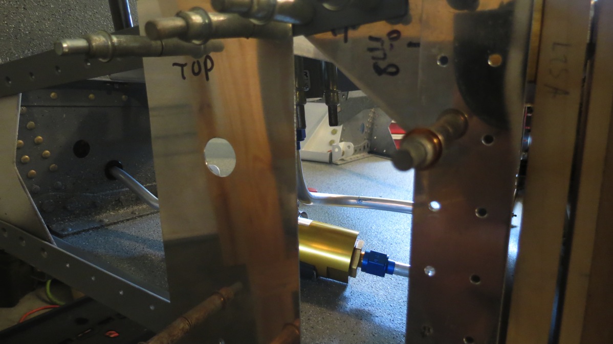
I started out trying to make the line between the fuel selector and the filter, which wasn’t exactly sensible, since the line between the filter and pump was going to be the annoying one, but I was kind of punting on that particular problem. Except I managed to foul up two attempts at the select-filter line in a row, for various and sundry reasons. Then, I oddly decided that maybe the filter-pump line was a better idea. And surprisingly enough, it went pretty well. I knew going in that I would have to flare at least one end of the line in place – the flares won’t pass through the snap bushings where the line goes through the gear towers. Fortunately, I didn’t have to do the actual bending in place; that would have been no fun at all. I actually got this one done on the first try; despite the annoyance of going through the tower, it’s a much simpler line than the other ones, with just two very slight bends.
Out of the filter…:
…through the tower…:
…and into the pump:
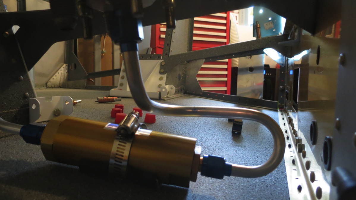
Next up was that pesky selector-filter line. This time I took a few moments to figure out the dimensions of the bends from my tubing bender – approximate radius and circumference. This allowed me to plan the line a bit better. A fun thing to consider while working on this is that the line from the right tank will be attached to the center section web in close proximity. To simulate the presence of that line, I put a length of tubing into a coupe of the adel clamps that will hold the actual line – this way I could be sure the two lines wouldn’t be rubbing or anything undesirable like that.
The finished selector-filter line:
Then there was the line to the left tank. Here, I took a few minutes and made a template from one of the forward side skins so I could approximate the passthrough hole for the fuel line:
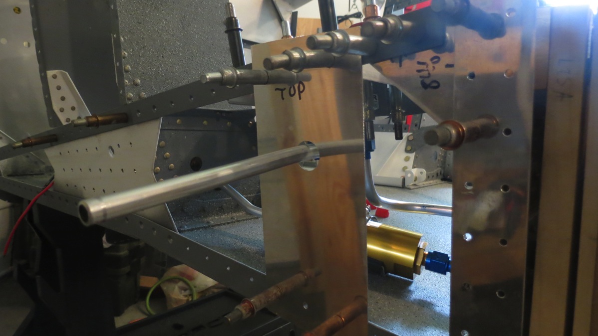
The line here was pretty simple too; just down from the selector, a 180° bend back up to the passthrough, and a 90° bend to go through the hole. My previous note of the bend radius made this actually match up on the first try:
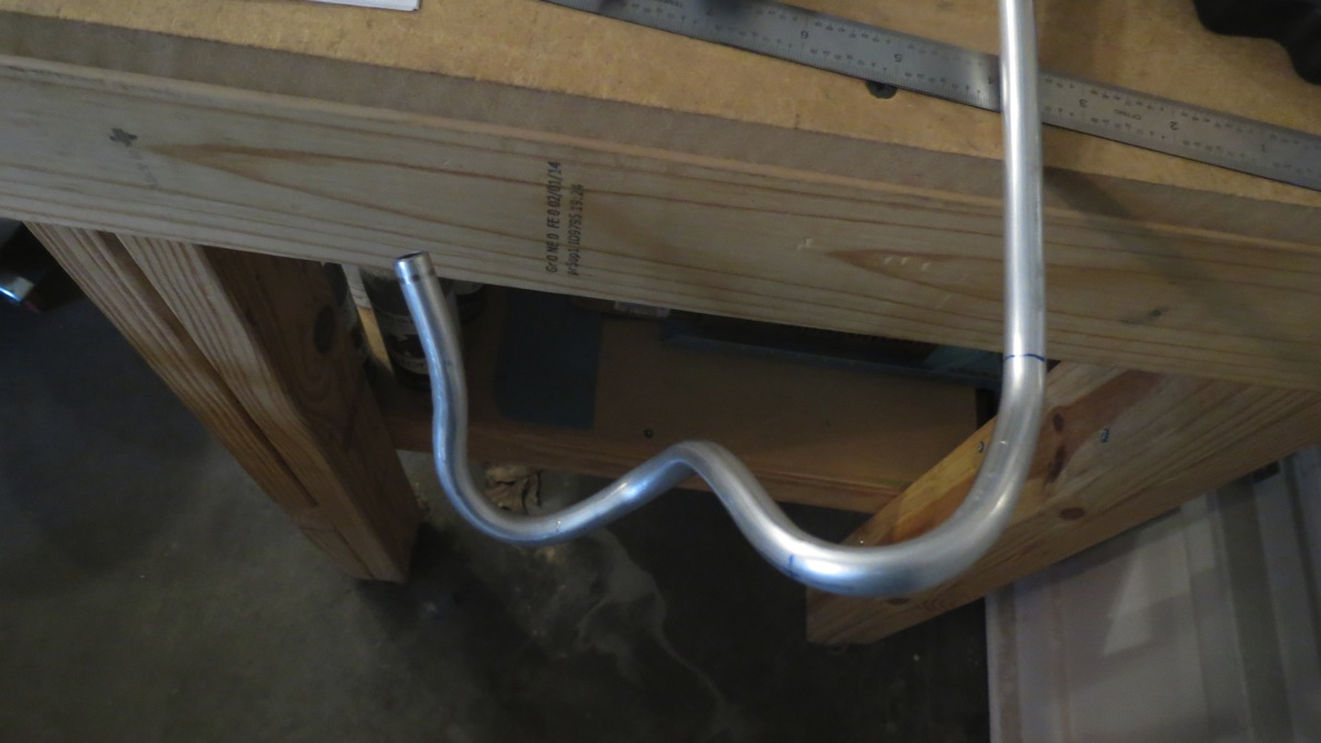
That only left one more line – the long one over to the right tank. Amazingly enough, despite my early mistakes, I still had enough tubing left to make this line. So I measured everything carefully, plotting out my first couple bends to get from the selector back to the center section web, did my bends, and…I forgot to subtract the bend radii. With the line against the center section, the end by the selector was at least 1.5” too far forward. I tried to salvage the line by adding some extra bends to account for the extra length, but it was too much – eventually I started to collapse a couple of the bends, and so I admitted defeat. This is the modern art masterpiece that resulted from trying to salvage that line:
So I’ll have to order some more tubing from Spruce this week. The good news is that this stuff is super cheap, like 75 cents a foot.
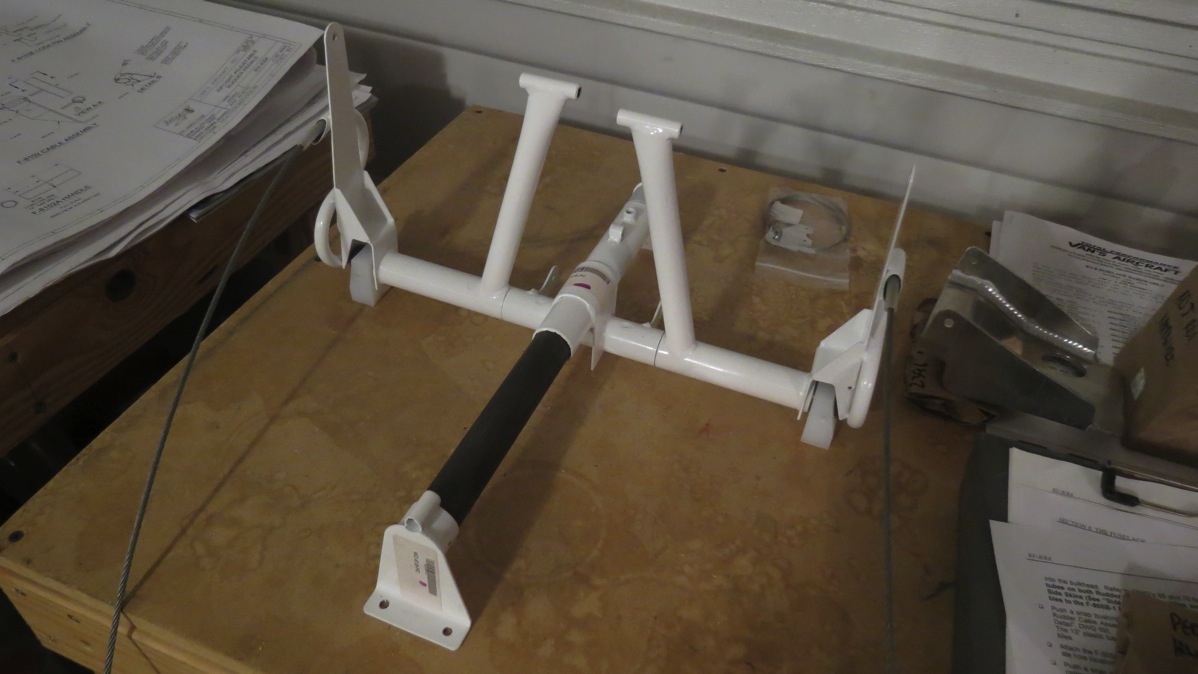
I wasn’t quite ready to quit for the day, so now what? I could either keep with the tubing-bending fun and work on some brake lines, or I could start paying with the rudder pedal assembly. The latter seemed like a lot more fun, so I started a full-fledged hunt for all the required parts. Rather than just jumping into the assembly instructions, I started roughly assembling the parts just to get an idea of how everything went together. But I could only go so far without having to final-drill some holes. I’d hoped to at least get the brake pedals in place so it looked like something…but they needed final drilling, So I just ended up with this:
The first actual assembly step was to final-drill the mounting bole holes in the slide bar to #12, so the assembly could be temporarily bolted into the fuselage. Well, I got exactly two holes drilled on the drill press; on the second one, the piece slipped, and the drill bit caught and promptly detonated. The part turned out OK, but obviously I needed a new drill bit. Oh, look – it turns out that was the only #12 drill bit I have. I had extras of literally every other size except for #12. Well, that pretty much put a stop to work on the rudder assembly – it seems that every hole in this thing is #12.
I tinkered a bit with the brake system, looking over the line layouts and gathering parts, but ultimately I didn’t really get anything done. I’m going to have to modify the line routing here a bit, so I’ve got to figure that out. The plans route the brake lines through the second lightening hole from the top in the gear towers – but that hole is in the middle of the removable plates I made. Having a brake line go through the would kind of put a kink in the whole “removable” thing. So I guess I’ll have to route the lines a bit higher and go down through the top hole.
Anyway, I’m going to sleep on that and give it a whirl tomorrow, I suppose. I’ve done enough damage for one day.