Well, today turned out to mostly be a construction day. I set off for Home Depot with a bit of a shopping list and came home with quite the assortment of lumber. The first thing I wanted to get done – which I’ve been planning for a while now – is a work surface for building the ailerons and flaps. The instructions specifically mention using a good flat surface when building these parts, lest one accidentally build in a twist. Problem is, my workbench tops are not flat, they both have a bit of bow to them. After some research, I went with an idea I got from VAF to construct a work surface. The basic idea is to use two pieces of MDF and sandwich pieces of good straight hardwood between them. The result is a very stiff unit sort of reminiscent in construction to a hollow core door.
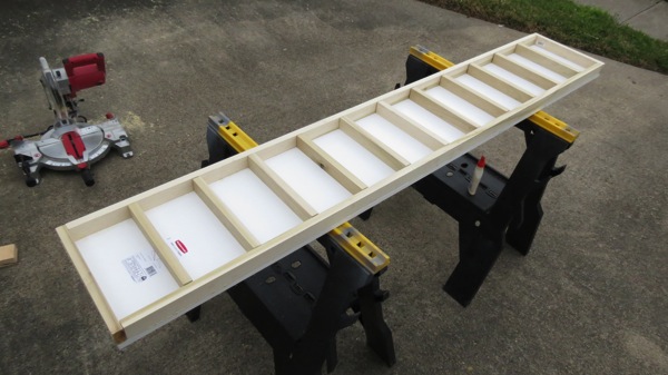
In lieu of MDF that I’ve have to cut – which I hate doing, it generates ridiculous amounts of fine dust – I bought two 12”x6’ veneered MDF shelves, along with a few pieces of 1×2 poplar (and I spent a fair amount of time going through the pieces of poplar to find really good straight ones). Once home, I cut two long poplar pieces to go lengthwise on the shelves, then cut the rest of what I had into short cross pieces. Then there was a lot of measuring, drawing layout lines, and so forth, until I finally got to start putting stuff together. The shelves and poplar pieces are joined using wood glue and finishing nails. Here’s the first shelf with all the poplar nailed/glued in place, just before I put the other shelf on:
After nailing/gluing the second shelf to complete the sandwich, I put the finished unit on the sawhorses and used a digital level to check for twist:
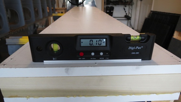
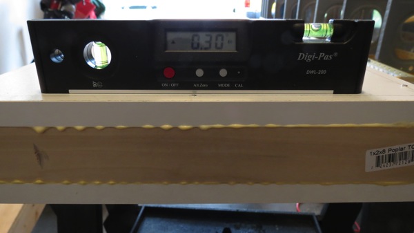
I figure .2° of twist is an acceptable margin of error. And before anyone feel compelled to comment that it’s actually .4°, remember that the level was rotated. so the sign of one of those numbers has to be inverted before comparison. So it’s not .3 – -.1 = .4, it’s .3 – .1 = .2. Anyway, sorry for the math lesson.
With that done, I moved on to putting together the bending brake. I’d already cut the 2×6 I had into two lengths for this earlier, so now all I had to do was install the hinges to make the brake. I didn’t get any pictures of the brake by itself, because I was so eager to use the thing that I recruited Josie to come out and help me complete the skin bends. Here’s a 100% staged photo of the bending process:
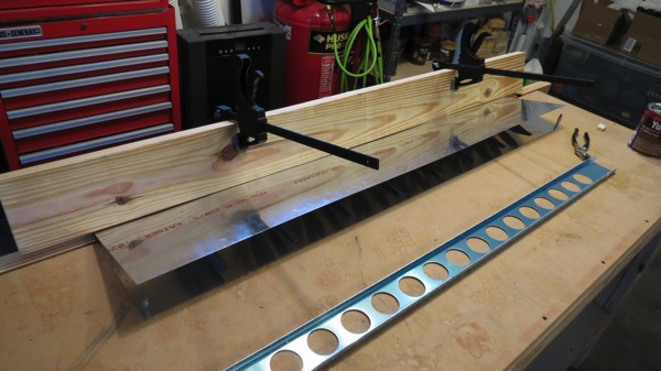
Note the two large clamps on the top half of the brake. These were necessary in order to get sufficient leverage. That is, I couldn’t get the skin to bend simply by pushing on the board itself. In fact, to get the bend done, I was pushing down on the ends of those clamps with most of my (considerable) body weight while also leaning into the top of the board. If you’re wondering if it feels wrong to put that much force into a carefully-constructed aircraft part, then you’re 100% right. Funny thing is, I did this same thing with the elevators and rudder and I don’t remember it being this bad. I think maybe those skins were thinner than the aileron skin, but who knows.
Anyway, after finishing both bends, I clecoed the aileron spars into place so I could check the bends. The plans say the skins should be straight right up to the bend, and the bend itself should have a 1/8-3/32 radius. My bend radius actually came in a hair under the minimum (5/64), but I imagine that should be fine. It’s not as if I’m off by a huge degree. And the skins right up to the bend do look nice and straight:
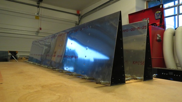
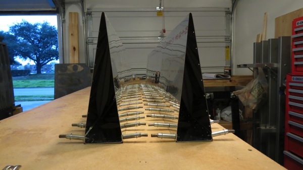
After that, I removed the spars and went to work preparing those. The next step in the plans is to clamp the spar reinforcements into place and match drill with the spar ends, then clamp the hinge points into place and drill their mount holes to full size. I meant to get a photo of this assembly, but I got carried away and tore everything apart for deburring before I remember about the photo. Whoops. I’m sure you’ll get to see it at some point down the road.
(Somewhere in the middle of all this I remembered that I was going to rivet the flap braces today. I got so carried away with the ailerons that I forgot. Guess I’ll backtrack to that maybe tomorrow night.)
Anyway, that’s it for tonight. Tomorrow my Stewart Systems epoxy primer is supposed to arrive, which is good, since I want to use that on the aileron counterweights. If I haven’t mentioned it before, the counterweights are galvanized water pipe. I want to take particular care to avoid having any direct contact between the steel pipe and the aluminum skins, to head off any possible galvanic corrosion. Probably overkill, but hey, it’s a primary flight control. Plus it’ll be a good thing for me to try the epoxy primer out on.
Update: I did a bit of research about the trailing edge bend radius. It seems that the bend radius has a significant effect on control forces; a larger radius reduces forces, whereas smaller increases them. Similarly, if the skins are slight convex up to the bend, this decreases forces, and concavity would increase forces. Some reports are that any significant concavity can lead to the ailerons being so sensitive as to be unpleasant…I’ll be paying close attention to that when the ailerons come together for good. But my slightly-undersize bends err on the better side, I think. It sounds like I can always increase the radius a bit by tapping on the bend with a piece of wood to swell it a bit, but I’m not going to bother with that unless flight testing makes me feel that the roll forces are too much. Even then, I think it’d have to be pretty bad for me to go monkeying with the ailerons.