Yet another multi-way post. When we left off last time, I’d been working on trimming the baffles in an attempt to get the lower cowl in place. At that time I thought I was pretty close when I quit for the night. Turns out I was “pretty close” in the same way that I’m “pretty close” to having a flying airplane…
Basically, it took about another four or five iterations of 1) remove some material, 2) clean up the cut edges, 3) try to put the cowl in place, and 4) find the new spot where something was interfering. But eventually, I got the lower cowl attached with the baffles in place:

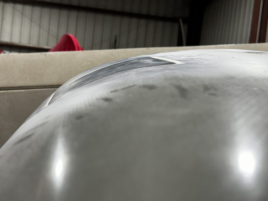
That got me to the point of laying the upper cowl in place just to try and get a very generic idea of what I’d be trimming and where. That line of thought also led me to go read through the instructions to try and get a high level idea of how things fit together. I was specifically interested in how the baffle ramps and the forward side baffles pieces interfaced with the cowling inlets. None of that was immediately relevant to work that needed to be done, but it’s always nice to clear up the big picture a bit.
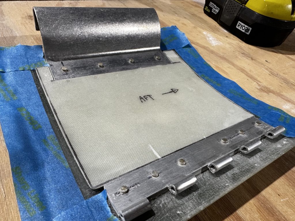
The next time I got out to do some work, it was pretty unseasonably warm. This was a good thing, because something I needed to address before even thinking about trimming anything was adding the upper inlet ramps in the cowl. These are two fiberglass curved pieces that basically block off the hollow area inside the inlets, preventing turbulence from the air entering and keeping it smoothly moving towards those toasty cylinders. These ramps get located on either side of the upper cowl and epoxied into place. And that’s why the weather was important – fiberglass epoxy doesn’t like to kick off when it’s cold outside, but 75° and sunny works just fine.
That’s a really long introduction for the next photo, which shows the ramps clecoed in place, right after I’d gooped the mating surfaces with epoxy and a bit of flox. These will later need to be sanded, and I’ll probably add some cloth at the interface just to reinforce things a bit:

After that, it was back to sheetmetal work. I was going through the baffle instructions and trying to figure out what stuff I could do right now. Eventually I decided it’d be a good use of time to start match-drilling and deburring the forward ramp parts. The goal was to go ahead and rivet these subassemblies together, but…this got me to the point of needing to address those custom baffle pieces for the tapered Titan cylinders. Those pieces will need to be riveted in assembly with all those other parts.
As mentioned before, other builders have gone before me here, so all I had to do was download some handy PDF templates (linked here for credit to the creators, as well as to help if anyone else is reading this and needs them). After printing those out and verifying the scale of the printouts, it was time to do some arts & crafts work. First I cut out the paper templates, then taped them to a manila folder and cut out some more rigid templates (much better for tracing on aluminum):

Then I got to trace those on some aluminum sheet stock and cut them out, followed by lots of filing, sanding, and other joyous tedium:

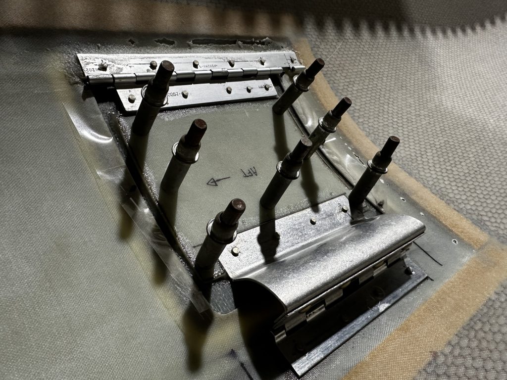
Then there was the real fun, lots of bending. The flanges were pretty easy – mostly just 90° bends, which I was able to do in my trusty Harbor Freight bending brake – but getting the curve around the cylinder was a little more fun. The aluminum is a bit too thick to just sort of bend freehand, but eventually I worked out some techniques with the vise and scrap wood to get things looking pretty good. It’s helpful that I don’t need to get the curve perfect here, because these pieces will be pulled tightly in place by retaining rods when they’re done. So they just need to be relatively close:

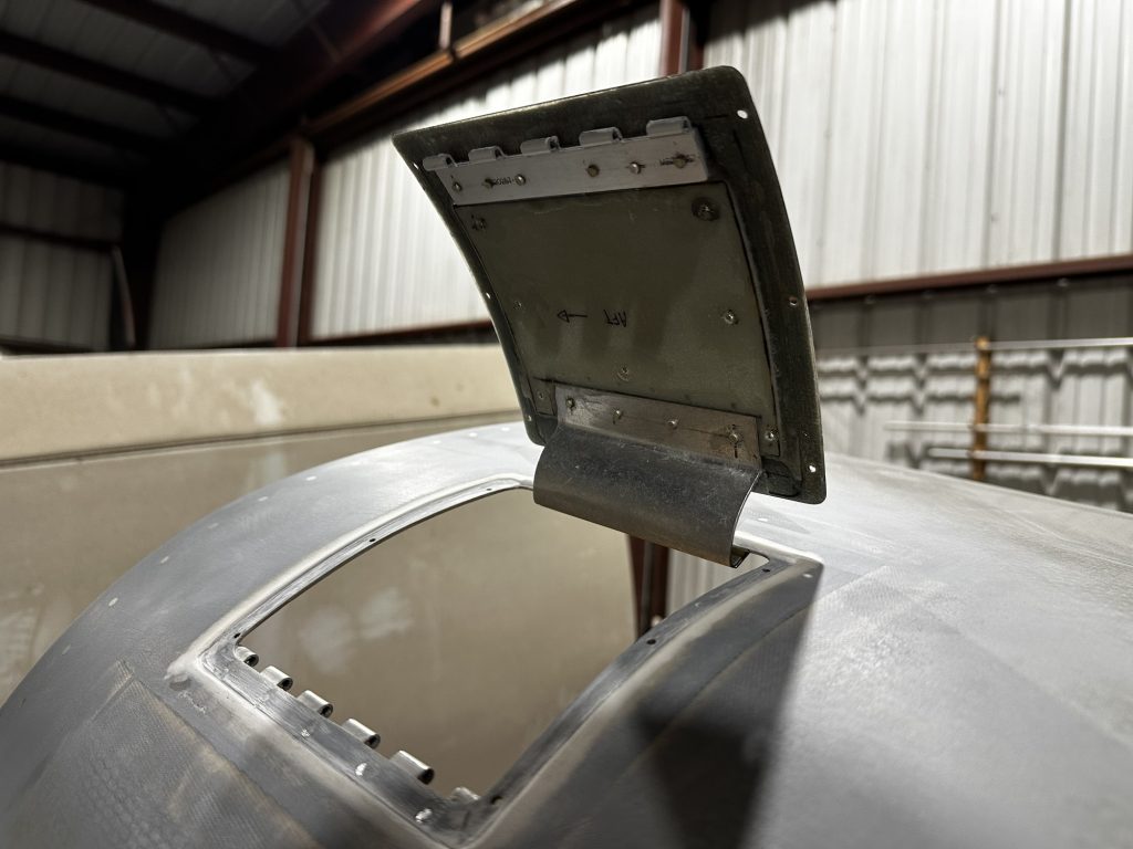
There was one piece that was more challenging than the rest, though; the #3 baffle has this little stair-step bend in it, which is basically closing a gap between the matching rear baffle (which is vertical) and the tapered cylinder. It took a decent amount of thinking to figure out how to do this, and in the end it involved me cutting scrap wood into a properly-shaped wedge to help things out. The actual bending I had to do with hand seamers – no way to get a bending brake or anything like that in here for the second and last bend:

This is a top-down look at that piece in place, showing how that little joggle will fill the gap here:

At the end of the night, I had all four of these tapered baffle pieces bent and ready to go. I guess tomorrow I get to figure out how in the world to clamp these pieces in place so I can drill in assembly with the rest of the baffles.