Another multi-day entry here; been kind of tinkering with this stuff intermittently over the past few days. On Friday, rather than going back to messing with the crank sensor cable guard again, I decided to get back to my primary goal, which was to figure out cable/wire routing under the right side of the engine.
First up was the big item, namely the primary alternator feed. The big item of concern here is that the fuel line to the injector servo runs in this same area, and by necessity it’s going to exist in close quarters with the alternator feed. Since the fuel line is metal braid, and will have a path to ground, the concern here is the possibility of that alternator feed ever being able to ground fault to the fuel line and become a nasty fire hazard. This is one of those items where I feel like the word “overthinking” doesn’t really apply – it’s worth being really careful.
To get better access to tinker with this, I removed the exhaust and intake pipes. Doing trial-and-error fitting while working around those was going to be no fun at all. After a good bit of that trial-and-error, I came up with a routing that I was happy with. At the point where the cable and line are closest together, I used a pair of Adel clamps to ensure they’d keep their distance. Further back, I anchored the cable to a sump bolt. Past that point, it goes away from the fuel line, but then it has to pass close to one of the engine grounds I added, so that spot has a dedicated standoff as well.
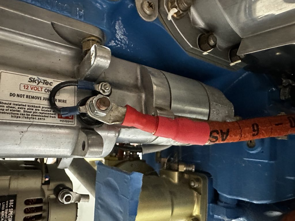
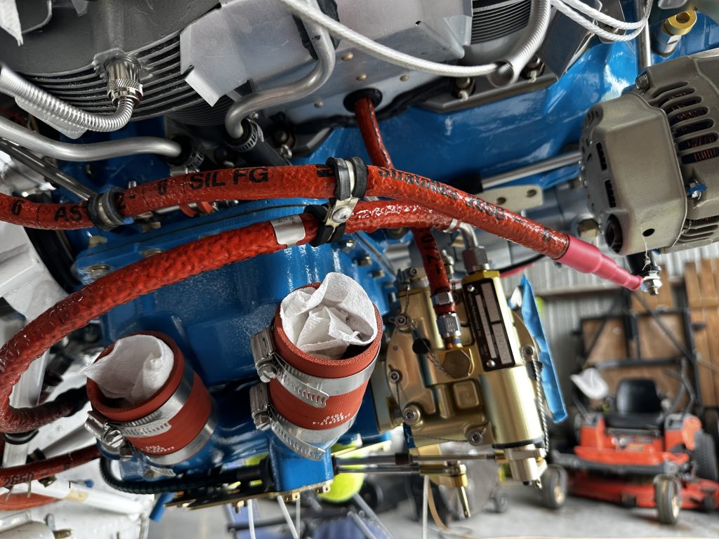
As with the starter cable, I elected to wrap this cable in firesleevea since it’ll be sitting close to the exhaust. After the requisite fitting and experimenting, I got all the fabrication done and routed the completed cable. Here we can see how it’s secured and stood off from the fuel line under the cylinders:
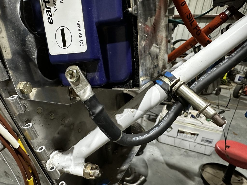
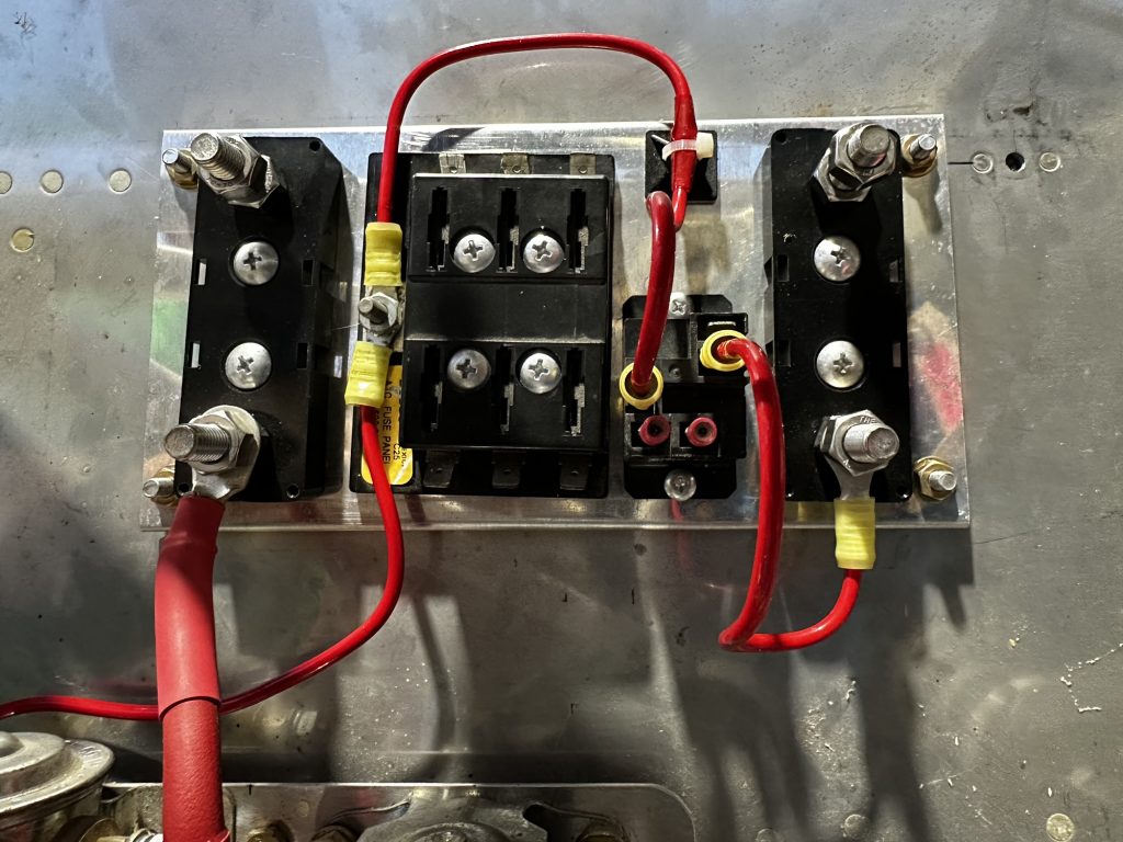
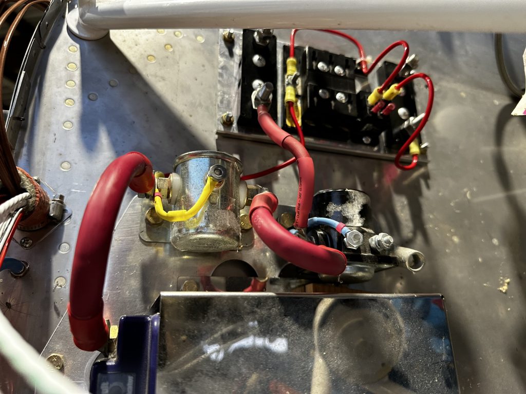
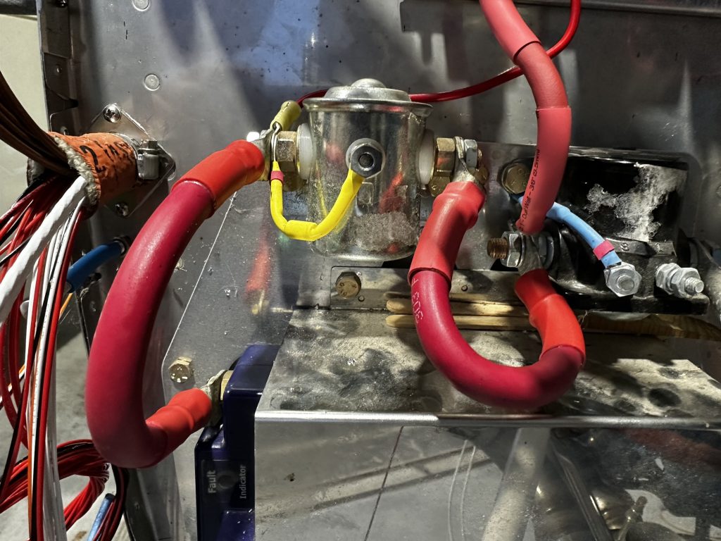
Further back, it crosses the ground cable, then route goes up the engine mount ring, and has one more standoff to the engine wiring bundle before making it to the junction with the battery and standby alternator feeds:
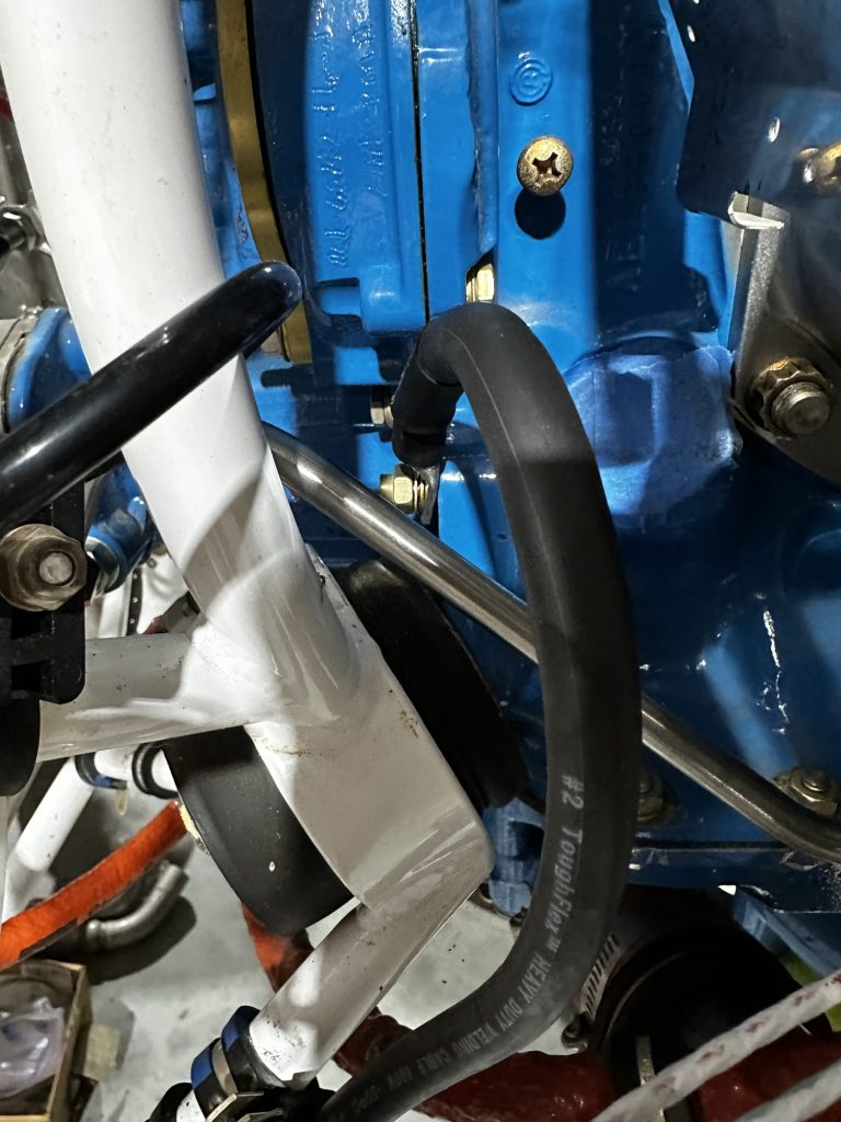
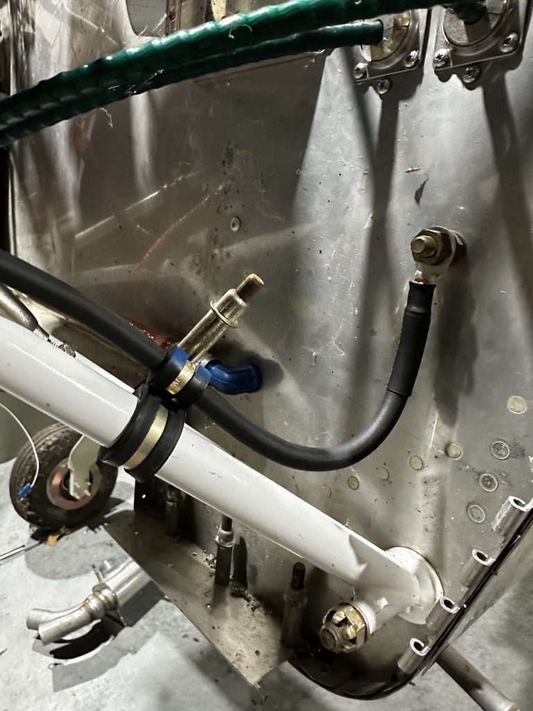
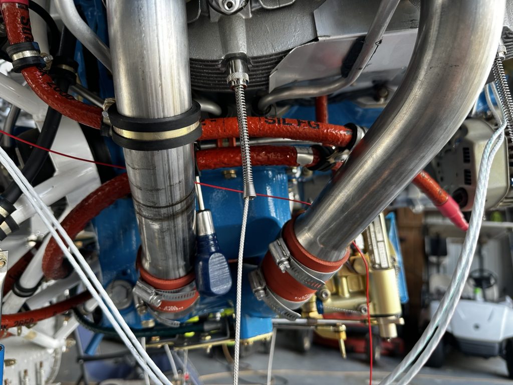
Then came the next moment of truth: I reinstalled the intake pipes to see how everything fit together. After looking at this, I made some routing modifications. Previously, the fuel line was secured to the #4 intake pipe, but that I didn’t like how that setup handled the proximity of the cable and line. So I ended up switching up the mounting; the cable is now secured to the intake pipe, and there’s another pair adel clamps keeping the fuel line at a distance. Kind of hard to see the latter here, but it’s there:
Then came the consideration of the other wires here. Initially I’d planned to route all four thermocouple leads inside the intake pipes, but given how things are a little crowded there, I think it’ll be smarter to route them around the outside. That just leaves the alternator field wire and the crank sensor leads to get routed alongside the alternator cable.
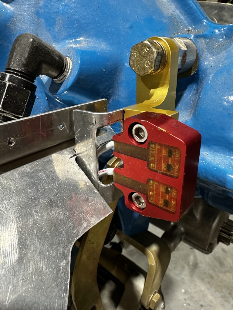
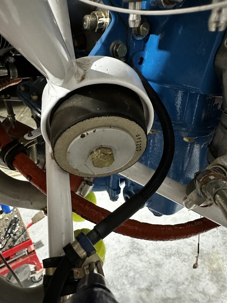
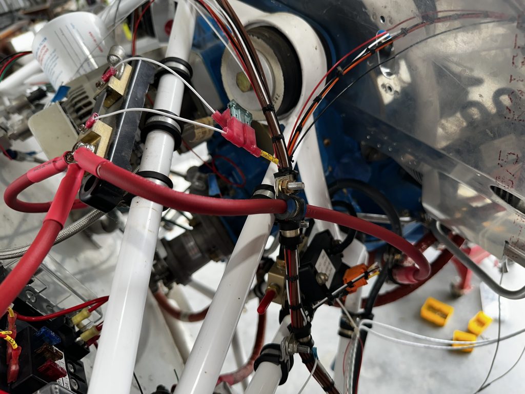
But before I could do much with those, it was time to confront the real fun of routing the crank sensor lead up by the intake ramp. Routing under the cylinders isn’t bad, but figuring out how to handle the lead close to the sensor itself is giving me fits. The leads are pretty stiff, and the angle at which they exist the sensor really want to have them rubbing on the edge of the ramp, which is no good at all. And that’s before I even get into how it should route relative to the prop oil line and the alternator bracket, all in the same area:
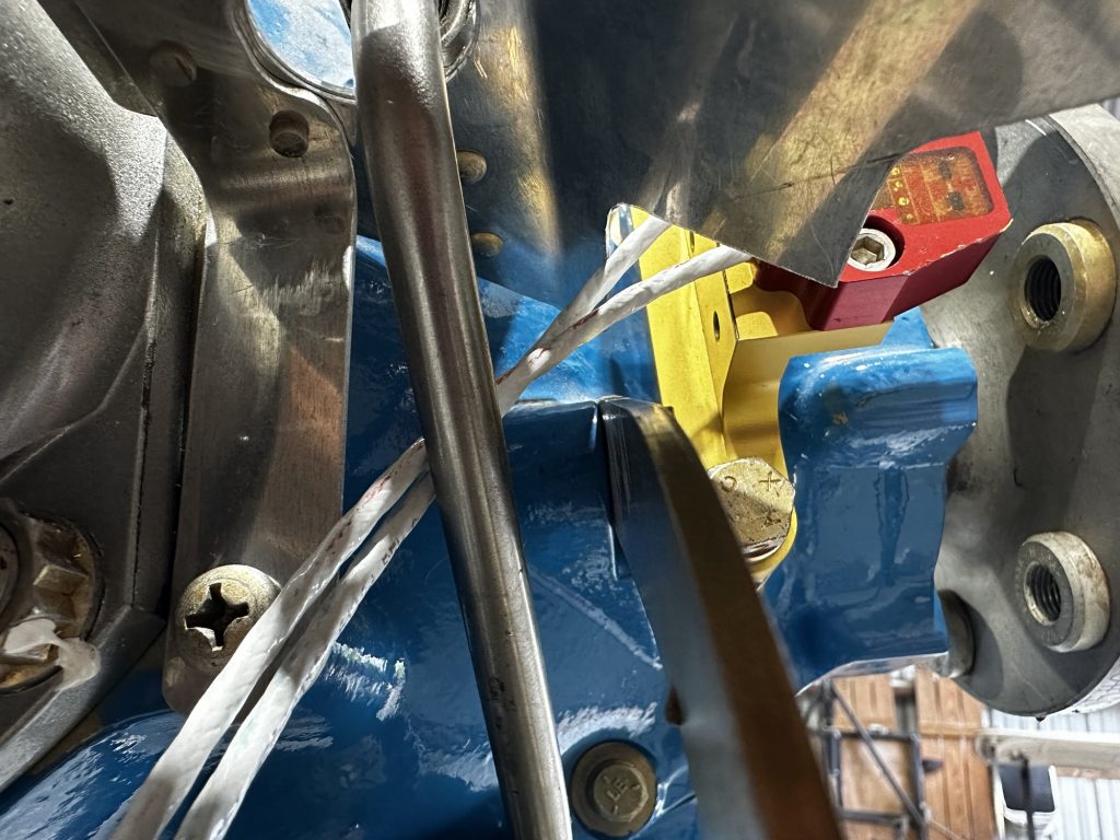
So far I’ve experimented a bit with an adel clamp or cable guide on the back of the cable guard, but neither of those made me particularly happy. After looking at that last photo, I’m considering maybe having an adel clamp or two under the ramp for routing, but that’s going to require more experimentation…which will be a job for another day.