Firewall Forward

Power distribution panel

Well, that was quite a productive day…seems like as of late, even when I work on stuff on the weekends, I can only squeeze out a few hours. Today I managed to get in basically a full day’s work, and ended up with a nice payoff.

I’ve been sort of wracking my brain over today’s assembly for some time. I knew I needed to mount a few fuse holders, plus the E-bus relay, on the firewall, and I was pretty sure I wanted to mount these items to a panel, and then mount the panel to the firewall, rather than just direct-mounting everything. The main reason for this is to have only four new holes in the firewall instead of ten. A side benefit is that if stuff needs to be modified down the road, it’ll be possible to modify or replace the panel, instead of turning the firewall inset Swiss cheese.

About a week ago I made a cardboard mockup just to test the layout of everything, and ensure that it’d all fit where I wanted it. Today I actually got to work on building the panel. It’s fairly straightforward – just a rectangular piece of sheet, to which I added 1/4” flanged top and bottom for some stiffness. It mounts to the firewall at the four corners; the top two screws go through one off the angles, while the bottom two are just through the stainless.

Actually building this was more involved – I worked out an order of operations for things to go relatively smoothly, cutting the panel piece, laying out the flange bends, then the attach screw holes, then transferring those holes to the firewall. That part required some creativity, because things were tight in a few places thanks to the engine mount tubes.

I didn’t bend the flanges until I’d laid out the attach holes for all the components, and drilled the rivet holes for the nutplates. Only then did I bend the flanges in my little sheetmetal brake, followed by riveting a bunch of nutplates, mounting the parts, and doing the most fun part – building out the various wires. I did what I could with the panel on the bench, before mounting it in the airplane and working on integrating it with the battery/contactors/etc.

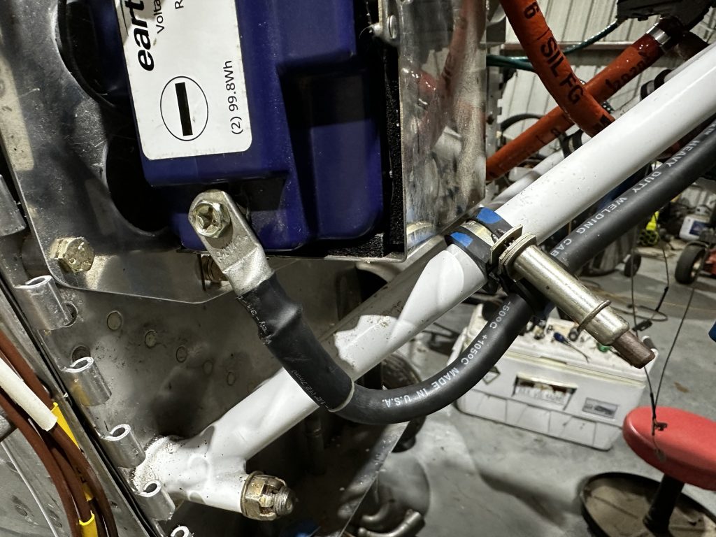
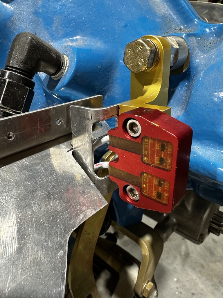
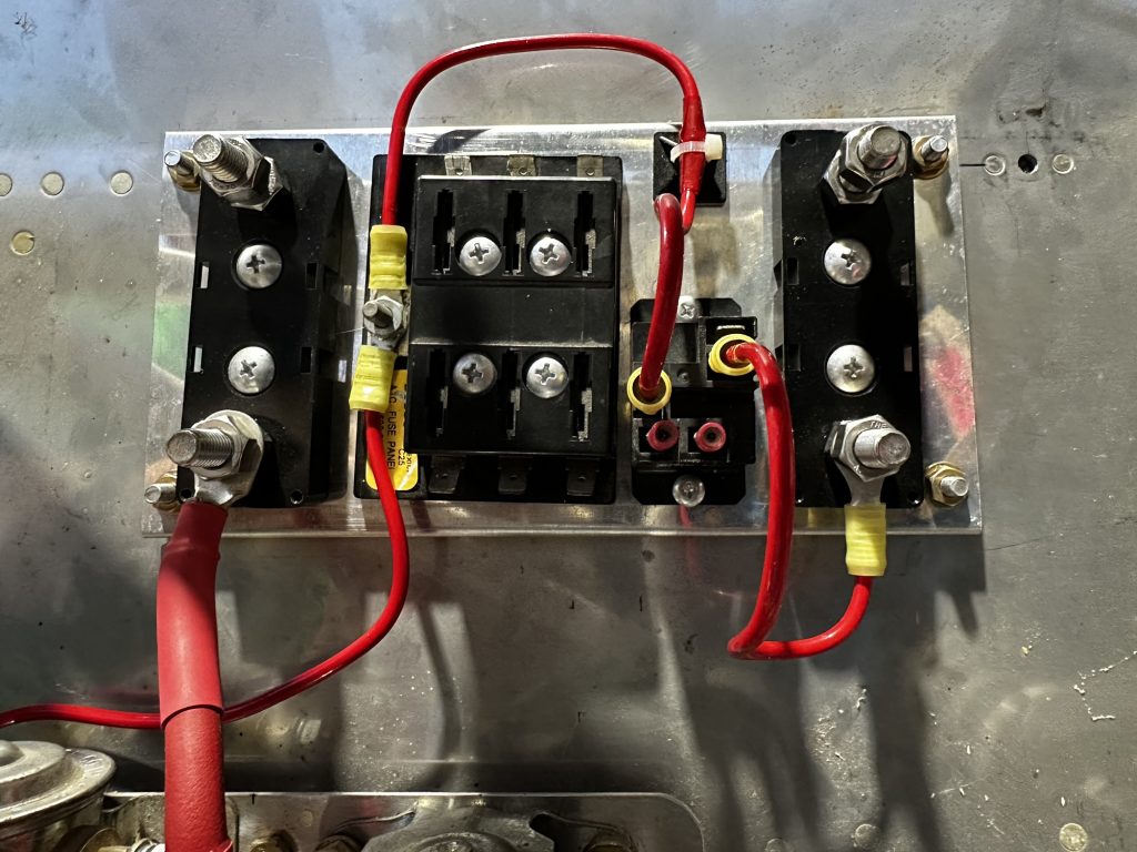
Here’s the final product mounted on the firewall. From left to right, we have:

  • An ANL fuse holder for the main bus feed. This will protect all the circuits downstream of the battery and alternators.
  • The battery bus – just a small fuse block with a few always-hot circuits
  • The battery bus then feeds a relay, which can be activated by a switch in the cockpit. This provides a way to power essential equipment in the event of a master contractor failure
  • Another ANL fuse holder for the alternate feed

Obviously we’re still missing some things here, like the alternator feeds, and the cables from the fuse holders feeding across to the firewall penetration and into the cabin. This long runs will come later.

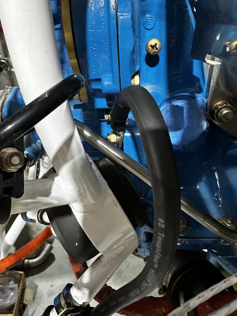
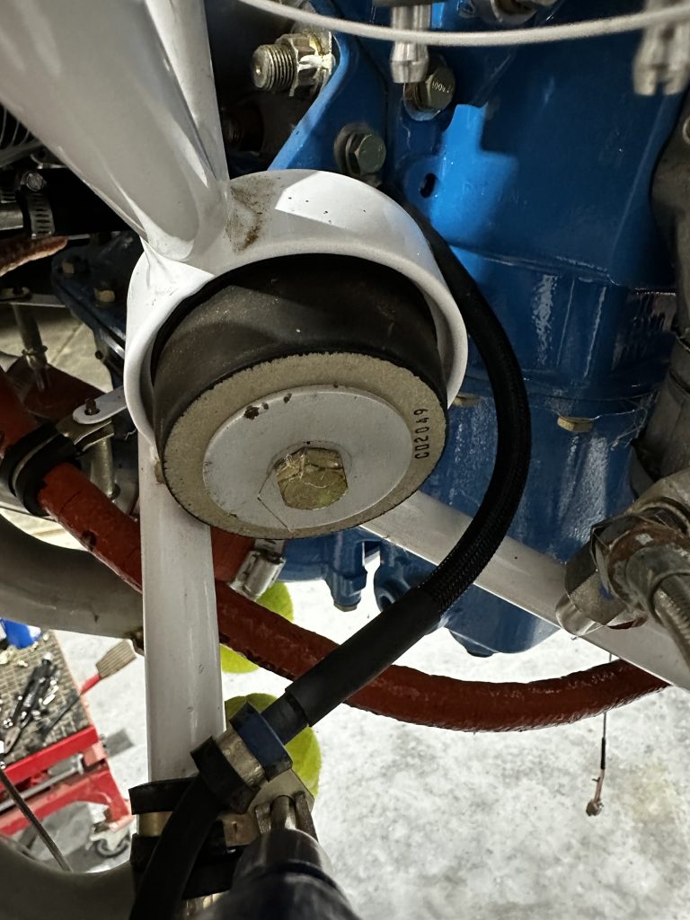
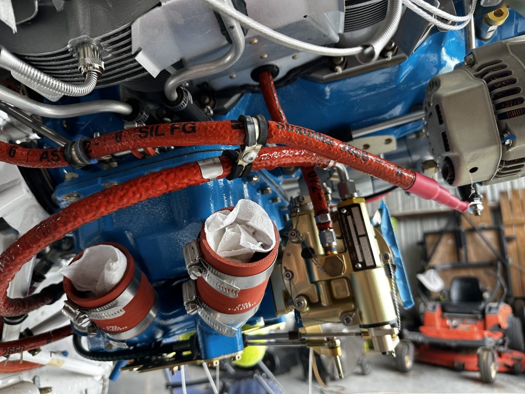
Here’s a slightly wider shot, showing how the panel sits above the contactors:

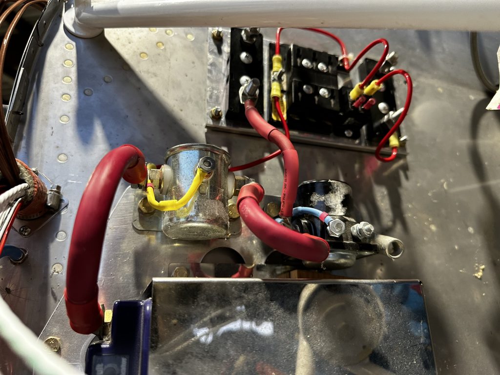
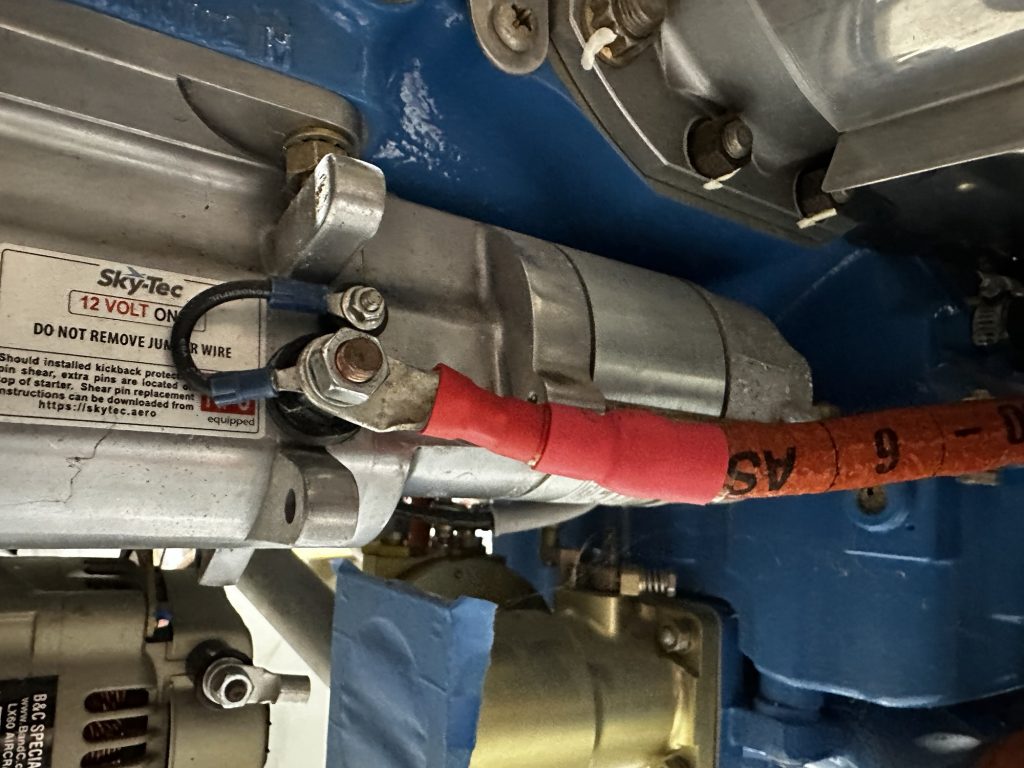
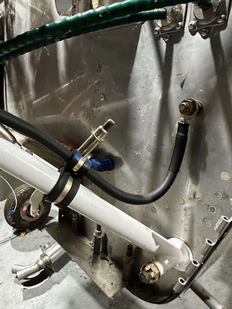
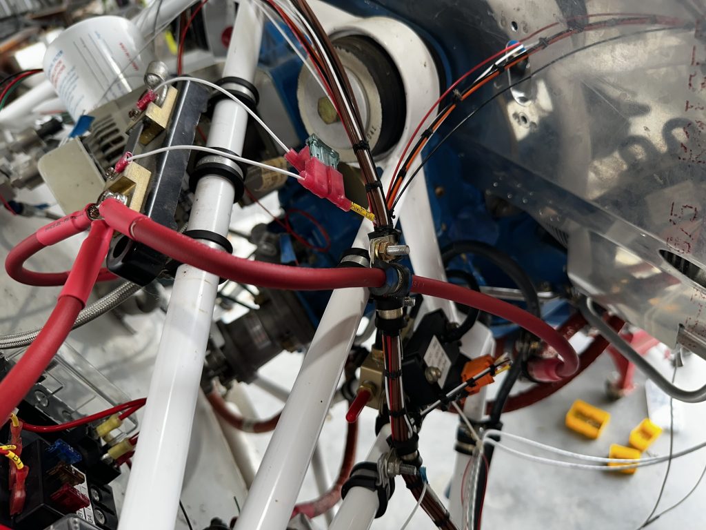
Finally, a closer look at the contactors, where I also fabricate a few of these cable/wire runs today. Visible here is the cable from the battery to the master contactor, a smaller tap from the hot side of the contractor to the battery bus, the big jumper from the master to starter contractor, and the tap from the hot side of the starter contractor up to the power distribution panel:

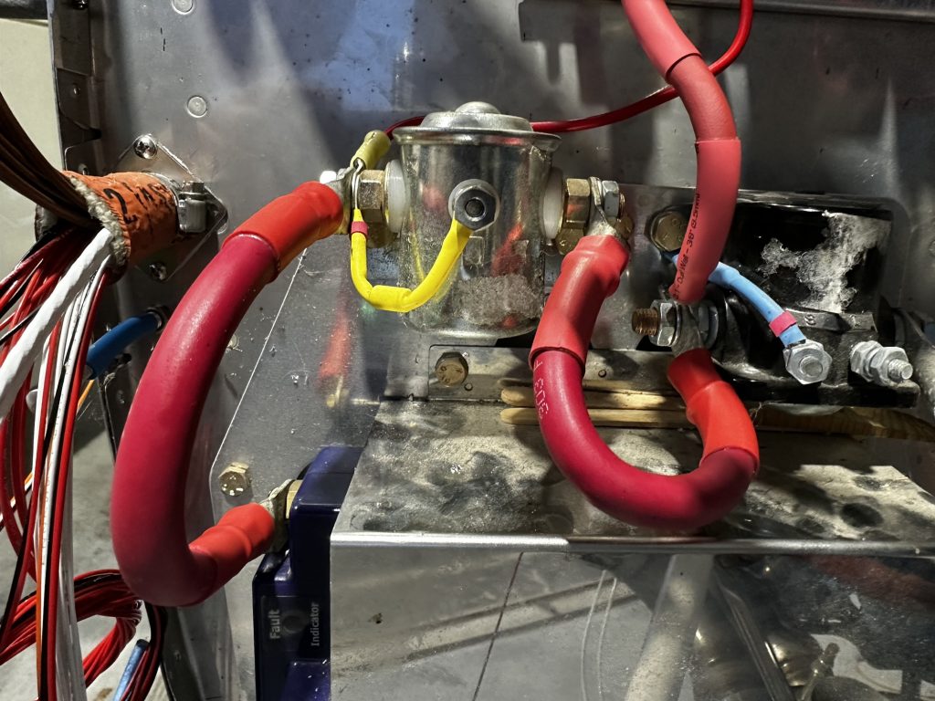
Of course, as I type this, I realize I made at least one mistake. I have a Hall sensor that I want run the battery bus tap through, so I can see how much current it’s drawing at any time. This will work in concert with a shunt on the main bus feed; the two together will give me a full picture of current flow.

Problem is…those terminals on the battery bus feed are too big go go through the Hall sensor. I needed to feed that cable through the sensor before terminating both ends. So I guess I’ll be prefabricating that cable at some point. Maybe tomorrow, assuming I have enough of the big terminals…

Posted in Electrical, Firewall Forward | Hours Logged: 9

Organizing FWF wiring stuff

So, the first order of business after the last work session was to fix that battery bus feed cable. It occurred to me that I didn’t need to completely re-make the cable; there was enough slack that just clipping off one terminal and crimping on a new one was perfectly fine. I did check for the proper orientation of the sensor about 47 times before I crimped on the new terminal, though.

That also led me to think about connectors; my intent has been to put in a three-pin Deutsch connector for the hall sensor, but if I do that I think I want to mount the connector to an engine mount tube, instead of having it hang around in midair. So I ended up ordering some little pads for that purpose, which should be here tomorrow.

From there, it was on to the sort of vague task of how to best organize the wiring runs, and how to actually work things into nice bundles. I decided a good way to make practical progress here was to start picking off the various wire groups, running them to somewhere near their sensor, and let that sort of flesh out the layout. To do that properly, I decided it was time to cut the hole in the right rear baffle where the coil pack and fuel flow sensor wires will go through.

After some thought, I decided the best way to do this was to drill two adjacent 3/4” holes and then open that up to a nice oval shape. That cutout is large enough to allow the coil pack plug to pass through, but will still be covered up by the grommet I bought. Then I laid out the screw holes for the grommet, drilled them, and installed nutplates. I got a picture of the hole itself, but I don’t have the right screws to actually install the grommet…plus that would have been purely for the photo op.

Next, I needed to figure out where to mount the manifold pressure sensor, along with the vacuum block that came with the CPI2 ignition. I ended up mounting those sort of back-to-back, since they’re connected together with a vacuum hose. I didn’t get a good photo of this, but if you look carefully in the following photo, you might see the gold-anodized vacuum block hiding back there.

With those items mounted, I could finally pull wires around. That still didn’t give me a great look at what the routing would look like, so I decided to use some temporary zip-ties to better mock up the harness run, along with where stuff would branch off. The result still doesn’t look super organized, but hey – it’s still a work in progress:

Of course, about the time I was taking this photo, I realized I forgot to include the CHT and EGT sensor wires in the bundles. Those should be fairly straightforward, though.

You might also notice the two stray wires at the bottom of the photo. These are the 5V and ground for the various sensors; they’ll need to serve three and four sensors, respectively, so I’ve got some window-splicing work to do. The general idea will be to pull them along the temporary bundles I have in place, figure out where to put the splices, and then I should be in a pretty good place to maybe start lacing some things up here and doing some terminations.

Electrical stuff is fun. Really.

Posted in Electrical, Firewall Forward | Hours Logged: 4

FWF wiring org, part 2

So as I’d hoped, I was able to start getting into some of the satisfying wiring stuff – routing wires to their final locations, trimming and terminating them, and lacing up bundles. It wasn’t all fun and games, though – as seems to be inevitable at this point, I had instances where I needed materials, or discovered a misstep from earlier. Nothing awful, just minor annoyances.

The first question was a classic one: where to start. It seemed to make sense to work from the firewall out, picking off branches as I got to them and working on the branches. Accordingly, the first thing I came to were the wires for the battery bus and contactors. On Tuesday I was able to get the four battery bus circuits taken care of, along with the switched ground wire to the E-bus relay. That was when I hit a misstep – I need a +12V source for the other side of the relay coil. Looking at my schematics, my intent was just to jump a small wire from the hot relay input. It’s an easy enough fix – cut the terminal and crimp on a new one, with a 22AWG wire tucked in alongside the 10AWG supply – but I don’t have the right terminal to redo that relay connection. First item on the order list right there.

OK, well at least I can pull the switched wires for the contactors while I’m in the neighborhood, right? They’re close enough that they might as well just get bundled along with some of the battery bus stuff. Except…I don’t have the right ring terminals for this. The ones I have are too small for the contractor studs. Yet another item on the shopping list.

But those were easy to tuck out of the way so I could move on. Next step before starting any more lacing was to splice in the +5V and ground wires for the hall sensor – which will also get wired alongside the other battery stuff. Getting those window splices done was a little fun, since I was working really close to the firewall fitting. Once they were done, I went ahead and laced the battery bus/contactor/hall sensor branch, then started working my way down the line.

The next junction was for the manifold pressure sensor. I was hoping to go ahead and get the termination done here, but the connector for this sensor is odd. After some research I determined it was a Weather Pack connector, and while I could probably do OK crimping the pins with what I had on hand, I decided to go ahead and order a specific crimping tool. At least Amazon had that for delivery tomorrow, is it skipped right past the running shopping list.

To make a long story short, I ended up adding the +5v and ground branches for both the MAP sensor and the fuel flow (well, fuel flow only gets ground, it runs off +12V). Those are all the branches I need on the right side of the engine, so I was able to lace things all the way up to where two branches split off – one for the fuel flow sensor and top mount coil pack, and another for the main ammeter shunt.

Before I really go any further, I want to get the CHT and EGT sensors installed so I can properly handle the wiring routing for those. So I put a top to lacing for the night, but did decide to go ahead and secure what I had laced to the engine mount tubes. A couple adel clamp pairs took care of this, and as of now the harness is looking pretty nice for the first couple feet:

Tomorrow I figure I’ll see about getting the MAP termination done, and maybe get those CHT/EGT probes mounted. The only thing that might delay me here are the various crimp terminals I need to order – I doubt I’ll get those this week, so it might be next week before I can sit back and feel like the FWF wiring is largely done.

That reminds me, I also want to order some standoff pieces from Van’s for routing wires along the sides of the engine forward – like the alternator/starter cables. The shopping list grows again…

Posted in Electrical, Firewall Forward | Hours Logged: 3.5

FWF wiring org, part 3

Yeah, I’m getting behind on build log posts yet again. Haven’t had any real extended work sessions, but I’ve been chipping away.

Last week, after getting my new crimpers, I got the connector done for the MAP sensor – which gave me the opportunity to fire up the panel and see an actual functioning engine readout. It’s not much, but it’s something!

Beyond that, I’ve been a little hung up on some parts on order, and I kept forgetting to place those orders, which didn’t help. But now  I have some terminals coming from Stein, plus an order with Van’s for the standoff pieces I’ll use for routing wiring near the sump. Not sure how long it might be before I get the Van’s order, though – I’ve heard they’re running behind on shipments, and they had messaging on their site to that effect as well.

I did get the CHT sensors installed; these are pretty easy. There are threaded holes in the cylinders to accept fittings, to which the actual sensors mount bayonet-style. I had to go in and clean up these holes, thanks to mud dauber activity…which in turn required removing the exhaust, as well as the #2 intake tube.

Then there was the matter of the EGT sensors. To mount these, I need to drill a hole in each exhaust pipe. Which means I have to decide where to drill that hole. After a fair bit of research, I ended up going with a position about 2” from the exhaust flange. Then I had to ensure that the probes – which project out a few inches – wouldn’t interfere with the spark plugs or the lower cowl. So I got to hang the cowl again briefly just to check clearances, which turned out to be fine.

So finally after a lot of thinking I took the drill to my expensive exhaust. In the end it was undramatic, but it’s always fun going with these sort-of irreversible actions. So now I have the EGT sensors mounted all around:

Finally, I did some other prep work for that upcoming sump routing. I decided it would be a good idea to put the prop governor oil line back in place, since it’s a potential conflict for the wires I’ll be running. When I removed that before, it was a real pain to snake it out around everything. I was smarter this time, and just went ahead and removed the exhaust and intake pipes on that side of the engine, which made things go a lot better. I’ll have to remove the line again at some point when I’m finalizing the baffles, but such is life.

Now I’ve just got to figure out what I can work on while waiting for those standoffs to come in. I suppose one thing to be thinking about is the lower spark plug wires – those will have relatively long runs from the mag pad on the back of the engine. Plus there are some other terminations I can still work on in the meantime.

Posted in Electrical, Firewall Forward | Hours Logged: 3